CN112263347A - Electric toothbrush - Google Patents
Electric toothbrush Download PDFInfo
- Publication number
- CN112263347A CN112263347A CN202011222012.0A CN202011222012A CN112263347A CN 112263347 A CN112263347 A CN 112263347A CN 202011222012 A CN202011222012 A CN 202011222012A CN 112263347 A CN112263347 A CN 112263347A
- Authority
- CN
- China
- Prior art keywords
- handle body
- drive
- toothbrush head
- transmission rod
- movable rod
- Prior art date
- Legal status (The legal status is an assumption and is not a legal conclusion. Google has not performed a legal analysis and makes no representation as to the accuracy of the status listed.)
- Pending
Links
Images


Classifications
-
- A—HUMAN NECESSITIES
- A61—MEDICAL OR VETERINARY SCIENCE; HYGIENE
- A61C—DENTISTRY; APPARATUS OR METHODS FOR ORAL OR DENTAL HYGIENE
- A61C17/00—Devices for cleaning, polishing, rinsing or drying teeth, teeth cavities or prostheses; Saliva removers; Dental appliances for receiving spittle
- A61C17/16—Power-driven cleaning or polishing devices
- A61C17/22—Power-driven cleaning or polishing devices with brushes, cushions, cups, or the like
- A61C17/24—Power-driven cleaning or polishing devices with brushes, cushions, cups, or the like rotating continuously
- A61C17/26—Power-driven cleaning or polishing devices with brushes, cushions, cups, or the like rotating continuously driven by electric motor
-
- A—HUMAN NECESSITIES
- A61—MEDICAL OR VETERINARY SCIENCE; HYGIENE
- A61C—DENTISTRY; APPARATUS OR METHODS FOR ORAL OR DENTAL HYGIENE
- A61C17/00—Devices for cleaning, polishing, rinsing or drying teeth, teeth cavities or prostheses; Saliva removers; Dental appliances for receiving spittle
- A61C17/16—Power-driven cleaning or polishing devices
- A61C17/22—Power-driven cleaning or polishing devices with brushes, cushions, cups, or the like
- A61C17/222—Brush body details, e.g. the shape thereof or connection to handle
-
- A—HUMAN NECESSITIES
- A61—MEDICAL OR VETERINARY SCIENCE; HYGIENE
- A61C—DENTISTRY; APPARATUS OR METHODS FOR ORAL OR DENTAL HYGIENE
- A61C17/00—Devices for cleaning, polishing, rinsing or drying teeth, teeth cavities or prostheses; Saliva removers; Dental appliances for receiving spittle
- A61C17/16—Power-driven cleaning or polishing devices
- A61C17/22—Power-driven cleaning or polishing devices with brushes, cushions, cups, or the like
- A61C17/32—Power-driven cleaning or polishing devices with brushes, cushions, cups, or the like reciprocating or oscillating
- A61C17/34—Power-driven cleaning or polishing devices with brushes, cushions, cups, or the like reciprocating or oscillating driven by electric motor
- A61C17/3409—Power-driven cleaning or polishing devices with brushes, cushions, cups, or the like reciprocating or oscillating driven by electric motor characterized by the movement of the brush body
Abstract
The invention relates to an electric toothbrush, which comprises a handle body and a toothbrush head, wherein the toothbrush head is sleeved on the handle body in a pluggable manner, a bristle group is arranged on the toothbrush head, the bristle group comprises a plurality of bristles, the bristles are rotationally arranged on the toothbrush head through a rotating seat, the bristles are fixedly arranged on the rotating seat, a movable rod is arranged in the toothbrush head in a sliding manner along the length direction of the handle body, a driving gear is arranged on the rotating seat in a linkage manner, a rack meshed with the driving gear is arranged on the movable rod, the movable rod can drive the rotating seat to rotate in a moving manner, a driving assembly for driving the movable rod to move in a reciprocating manner is arranged on the handle body, the driving assembly comprises a motor device and a transmission rod, the motor device is fixedly arranged in the handle body, the transmission rod is arranged on the handle body in a sliding manner along the length direction of the handle body. By adopting the scheme, the novel clothes hanger is simple in structure and comfortable to use.
Description
Technical Field
The invention relates to the technical field of toothbrushes, in particular to an electric toothbrush.
Background
In daily life, a toothbrush is used for cleaning the oral cavity in order to clean the oral cavity, but a manual toothbrush usually cannot clean teeth cleanly, and the gum bleeding and the enamel abrasion are caused by the non-specification of manual operation force and action. Electric toothbrush has appeared on the market now, and it includes the handle body and toothbrush head, and the internal motor core's of handle fast rotation or vibrations drive the toothbrush head and produce high frequency vibration, and the vibration transmission brushes teeth on to the brush hair of toothbrush head. However, the bristles transmit vibration to the teeth, which may cause the teeth to feel crisp and uncomfortable.
Disclosure of Invention
The invention overcomes the defects of the prior art and provides the electric toothbrush which is simple in structure and comfortable to use.
In order to achieve the purpose, the invention adopts the technical scheme that: an electric toothbrush comprises a handle body and a toothbrush head, wherein the toothbrush head is sleeved on the handle body in an inserting and pulling way, a bristle group is arranged on the toothbrush head, the bristle group comprises a plurality of bristles which are rotatably arranged on the toothbrush head through a rotating seat, the bristles are fixedly arranged on the rotating seat, a movable rod is arranged in the toothbrush head in a sliding way along the length direction of the handle body, a driving gear is arranged on the rotating seat in a linkage way, a rack meshed with the driving gear is arranged on the movable rod, the movable rod can move to drive the rotating seat to rotate, the handle body is provided with a driving component for driving the movable rod to reciprocate, the driving component comprises a motor device and a transmission rod, the motor device is fixedly arranged in the handle body, the transmission rod is arranged on the handle body in a sliding mode along the length direction of the handle body, an output shaft of the motor device can drive the transmission rod to slide, and the transmission rod is connected with the movable rod in a linkage mode.
By adopting the scheme, the motor device can have a speed reduction function and also can comprise a motor and a speed reduction structure, so that the rotating speed of the output shaft is reduced, the bristles are exposed out of the toothbrush head, the bristles are not necessarily perpendicular to the outer surface of the toothbrush head and can be arranged at a certain angle, the rotating seat rotates on the toothbrush head and cannot be separated from the toothbrush head, when the toothbrush head is sleeved on the handle body, the transmission rod is in linkage connection with the movable rod to realize synchronous movement of the two, at the moment, the output shaft of the motor device rotates to drive the transmission rod to perform reciprocating movement, the transmission rod then drives the movable rod to perform reciprocating movement, the rotating seat is fixed or integrally provided with a driving gear along the circumferential direction, the rack on the movable rod is meshed with the driving gear, the reciprocating movement of the movable rod can drive the driving gear to rotate, so as to drive, the toothbrush handle is simple in structure and more comfortable to use, and the toothbrush head can be pulled out of the handle body and replaced with a new toothbrush head.
The invention further provides that: the driving assembly further comprises a fluted disc, the fluted disc is rotatably arranged on the handle body through a rotating shaft, the axial direction of the rotating shaft is perpendicular to the axial direction of the transmission rod, an output shaft of the motor device drives the fluted disc to rotate, and the fluted disc can drive the transmission rod to reciprocate through an eccentric structure.
By adopting the scheme, the motor device indirectly drives the transmission rod to move through the fluted disc, and the eccentric structure is utilized, so that the structure is simple and more reasonable.
The invention further provides that: the eccentric structure comprises an eccentric sleeve and an eccentric block, the eccentric block is arranged on the fluted disc in a linkage manner, the fluted disc can drive the eccentric block to do eccentric motion, the eccentric sleeve is arranged at the end part of the transmission rod in a linkage manner, the eccentric sleeve is sleeved outside the eccentric block, and the eccentric block abuts against the inner wall of the eccentric sleeve to drive the transmission rod to move back and forth.
Through adopting above-mentioned scheme, the eccentric block is fixed or integrative setting is in one side of fluted disc, and when the fluted disc drove the eccentric block and is eccentric motion, the eccentric block contradicts the inner wall of eccentric cover to drive transfer line reciprocating motion, the direct overcoat of eccentric cover in eccentric block, simple structure, simple to operate.
The invention further provides that: the end part of the transmission rod is provided with a first connecting head, the end part of the movable rod is provided with a first insertion cavity for the first connecting head to be inserted, the first connecting head is inserted into the first insertion cavity to realize linkage connection of the transmission rod and the movable rod, the first connecting head is provided with a guide block or a first guide groove along the axial direction of the transmission rod, and the inner wall of the first insertion cavity corresponding to the first connecting head is provided with a first guide groove or a guide block for the guide block or the first guide groove to be inserted.
Through adopting above-mentioned scheme, the connection structure of transfer line and movable rod is simple, and the plug installation of being convenient for sets up first guide way on the first connecting head, sets up the guide block on the inner wall in first plug cavity, and the cooperation of pegging graft of first guide way and guide block realizes the direction installation of toothbrush head, simple structure.
The invention further provides that: the axial direction of the rotating shaft is perpendicular to the axial direction of an output shaft of the motor device, a driving gear is arranged on the output shaft of the motor device, and a driven gear meshed with the driving gear is arranged on the fluted disc.
Through adopting above-mentioned scheme, motor device's position reasonable in design reduces the installation space of handle body width direction, and the structure is compacter, and the driving gear rotates in step and sets up on motor device's output shaft, and driven gear is fixed or integrative setting is on the fluted disc, and motor device passes through the indirect drive transfer line of fluted disc and removes, and the driving gear also can play certain speed reduction effect with the driven gear cooperation, simple structure, reasonable in design.
The invention further provides that: the brush hair of brush hair group is provided with two rows to arrange along the length direction of handle body and distribute, two rows of brush hair lie in the both sides of movable rod, all are provided with drive gear on each brush hair, and the rack is provided with two to correspond drive gear setting, movable rod reciprocating motion can drive two rows of brush hair simultaneously and rotate.
Through adopting above-mentioned scheme, the movable rod can drive two rows of brush hairs simultaneously like this and rotate for overall structure is compacter, make full use of installation space.
The invention further provides that: the transmission rod is provided with a second guide groove along the axial direction, the handle body is provided with a guide post along the radial direction of the transmission rod, and the guide post is inserted in the second guide groove to realize the guide sliding of the transmission rod.
Through adopting above-mentioned scheme, the guide post is provided with two to the interval sets up, under the cooperation of guide post and second guide way, the transfer line receives the eccentric block to support the back, only can come the rebound along its axial, simple structure, reasonable in design.
The invention further provides that: the tip of toothbrush head is provided with the second connector, the tip of handle body is provided with the second that supplies the second connector to insert the establishment and inserts the chamber, and the cooperation is inserted with the second in the chamber to the second connector and peg graft.
By adopting the scheme, the handle body is simple in connection structure with the toothbrush head, and the toothbrush head can be conveniently plugged and pulled out.
The invention further provides that: the handle body includes the shell and sets up the mounting bracket in the shell, and motor device is fixed to be set up on the mounting bracket, is provided with the button key on the shell, still is equipped with total circuit board and battery on the mounting bracket, still is equipped with the lamp circuit board of taking LED in the shell, and the setting of lamp circuit board is provided with the printing opacity lid in the one end that the shell is close to the toothbrush head, and the shell is provided with corresponding lamp circuit board department.
Through adopting above-mentioned scheme, the battery is rechargeable battery, and the accessible charges the mouth and charges, and the battery is total circuit board, motor device and lamp circuit board power supply, and the steerable motor device of button key operation and LED lamp are bright, and the light of LED lamp can be followed and the printing opacity covers and see through out, plays the indicating action.
The invention further provides that: the drive gear is located the toothbrush head, and the circumference linkage is provided with the drive shaft on the drive gear, and the drive shaft stretches out the toothbrush head setting, and the drive shaft is sealed through sealed gluey and is cooperated with the toothbrush head is sealed, sealed fixed the setting of gluing at the overhead of brushing teeth, rotates a seat overcoat in the drive shaft.
Through adopting above-mentioned scheme, drive gear passes through the drive shaft and drives and rotate the seat and rotate to rotate the seat and be convenient for the dismouting with the drive shaft, consequently can change different brush hairs as required, sealed glue plays sealed effect, and water is difficult for getting into in the toothbrush head.
The invention is further described below with reference to the accompanying drawings.
Drawings
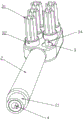
FIG. 1 is a schematic overall structure diagram of an embodiment of the present invention;
FIG. 2 is a schematic cross-sectional view of an embodiment of the present invention;
FIG. 3 is a schematic view of a toothbrush head construction;
FIG. 4 is a schematic view of the structure of the movable rod, the rotary seat and the bristles;
FIG. 5 is a schematic view of the handle body;
FIG. 6 is a schematic structural diagram of a driving assembly;
FIG. 7 is a schematic view of the movable rod;
FIG. 8 is a schematic view of the transmission rod;
FIG. 9 is a structural view of the toothed disc;
FIG. 10 is a schematic view of the internal structure of the handle body;
fig. 11 is a schematic view of a fitting structure of the guide post and the second guide groove.
Detailed Description
As shown in fig. 1-11, an electric toothbrush comprises a handle 1 and a toothbrush head 2, the toothbrush head 2 is sleeved on the handle 1 in a pluggable manner, a bristle group is arranged on the toothbrush head 2, the bristle group comprises a plurality of bristles 31, the bristles 31 are not necessarily perpendicular to the outer surface of the toothbrush head, and can be inclined at a certain angle, the bristles 31 are rotatably arranged on the toothbrush head 2 through a rotating seat 32, the bristles 31 are fixedly arranged on the rotating seat 32, the rotating seat 32 is rotatably arranged in the toothbrush head 2, the bristles 31 are exposed out of the toothbrush head 2, the rotating seat 32 cannot be separated from the toothbrush head 2, a movable rod 4 is slidably arranged in the toothbrush head 2 along the length direction of the handle 1, the movable rod 4 is slidably arranged in a sliding way through a structure of matching a sliding block and a sliding groove, a driving gear 33 is arranged on the rotating seat 32 in a circumferential direction in a linkage manner, a rack 41 meshed with the driving, the rack 41 is arranged along the length direction of the handle body 1, the movable rod 4 can move to drive the rotating seat 32 to rotate, a driving assembly for driving the movable rod 4 to reciprocate is arranged on the handle body 1, the driving assembly comprises a motor device 5 and a transmission rod 6, the motor device 5 is fixedly arranged in the handle body 1, the motor device 5 can have a speed reduction function and can also comprise a motor and a speed reduction structure, so that the rotating speed of an output shaft of the motor device 5 is reduced, the transmission rod 6 is arranged on the handle body 1 in a sliding manner along the length direction of the handle body 1, the output shaft of the motor device 5 can drive the transmission rod 6 to slide, and the transmission rod 6 and the movable rod 4 are connected in a linkage manner to realize synchronous movement of the.
In this embodiment, the driving assembly further includes a fluted disc 71, the fluted disc 71 is rotatably disposed on the handle body 1 through a rotating shaft 72, an axial direction of the rotating shaft 72 is perpendicular to an axial direction of the transmission rod 6, an axial direction of the rotating shaft 72 is perpendicular to an axial direction of an output shaft of the motor device 5, the output shaft of the motor device 5 is sleeved with a driving gear 51 in a linkage manner, a driven gear 73 meshed with the driving gear 51 is fixedly or integrally disposed on the fluted disc 71, the fluted disc 71 can drive the transmission rod 6 to reciprocate through an eccentric structure, the eccentric structure includes an eccentric sleeve 61 and an eccentric block 74, the eccentric block 74 is fixedly or integrally disposed on the fluted disc 71, the fluted disc 71 can drive the eccentric block 74 to do eccentric motion, the eccentric sleeve 61 is fixedly or integrally disposed at an end portion of the transmission rod 6, the eccentric sleeve 61 is externally sleeved on the eccentric block 74, and the eccentric block.
In this embodiment, a first connection head 62 is integrally disposed at an end portion of the transmission rod 6 close to the movable rod 4, a first insertion cavity 42 into which the first connection head 62 is inserted is disposed at the end portion of the movable rod 4, the first connection head 62 is inserted into the first insertion cavity 42 to realize linkage connection between the transmission rod 6 and the movable rod 4, a first guide groove 63 is disposed on an outer side surface of the first connection head 62 along an axial direction of the transmission rod 6, and a guide block 43 into which the first guide groove 63 is inserted is disposed on an inner wall of the first insertion cavity 42 corresponding to the first guide groove 63. Of course, the first connector 62 may be provided with a guide block, and the first insertion cavity 42 may be provided with a first guide groove.
In this embodiment, two rows of bristles 31 of the bristle group are arranged and distributed along the length direction of the handle body 1, the two rows of bristles 31 are located at two sides of the movable rod 4, each bristle 31 is provided with a driving gear 33, two racks 41 are arranged and arranged corresponding to the driving gears 33, and the movable rod 4 reciprocates to drive the two rows of bristles 31 to rotate.
In this embodiment, the driving rod 6 is provided with a second guiding groove 64 along the axial direction thereof, the handle body 1 is provided with two guiding studs 11 along the radial direction of the driving rod 6, the two guiding studs 11 are arranged and distributed at intervals, and the guiding studs 11 are inserted into the second guiding groove 64 to realize the guiding sliding of the driving rod 6.
In this embodiment, the end of the toothbrush head 2 is provided with a second connector 21, the end of the handle 1 is provided with a second insertion cavity 12 for the second connector 21 to be inserted, and the second connector 21 and the second insertion cavity 12 are inserted and matched.
In this embodiment, the handle body 1 includes the shell 13 and sets up the mounting bracket 14 in the shell 13, the motor device 5 is fixed to be set up on the mounting bracket 14, be provided with button key 81 on the shell 13, still be equipped with total circuit board 82 and battery 83 on the mounting bracket 14, still be equipped with the lamp circuit board 84 of taking the LED in the shell 13, lamp circuit board 84 sets up the one end that is close to toothbrush head 2 at the shell 13, the shell 13 is provided with printing opacity lid 15 in the department that corresponds lamp circuit board 84, the light of LED lamp can be followed and is passed through on the printing opacity lid 15, play the indicating action.
In this embodiment, the driving gear 33 is located inside the toothbrush head 2, the driving gear 33 is provided with a driving shaft 34 in a circumferential direction in a linkage manner, the driving shaft 34 extends out of the toothbrush head 2, the driving shaft 34 is in sealing fit with the toothbrush head 2 through the sealant 9, the sealant 9 is fixedly arranged on the toothbrush head 2, and the rotating seat 32 is sleeved on the driving shaft 34.
The above embodiments are merely preferred embodiments of the present invention, and general changes and substitutions by those skilled in the art within the technical scope of the present invention are included in the protection scope of the present invention.
Claims (10)
1. The utility model provides an electric toothbrush, includes the handle body and toothbrush head, the cover that the toothbrush head can be plugged is established on the handle body, is provided with brush hair group, its characterized in that on the toothbrush head: the brush hair group is including a plurality of brush hair, and the brush hair rotates through rotating the seat and sets up on the toothbrush head, and the brush hair is fixed to be set up on rotating the seat, it is provided with the movable rod to slide along the length direction of the handle body in the toothbrush head, rotates the seat and goes up the linkage and is provided with drive gear, is provided with the rack with drive gear looks interlock on the movable rod, and the movable rod removes and can drive and rotate the seat and rotate, be provided with drive movable rod reciprocating motion's drive assembly on the handle body, drive assembly includes motor device and transfer line, motor device is fixed to be set up in the handle body, the transfer line slides along the length direction of the handle body and sets up on the handle body, and motor device's output shaft can drive the transfer line and.
2. An electric toothbrush according to claim 1, wherein: the driving assembly further comprises a fluted disc, the fluted disc is rotatably arranged on the handle body through a rotating shaft, the axial direction of the rotating shaft is perpendicular to the axial direction of the transmission rod, an output shaft of the motor device drives the fluted disc to rotate, and the fluted disc can drive the transmission rod to reciprocate through an eccentric structure.
3. An electric toothbrush according to claim 2, wherein: the eccentric structure comprises an eccentric sleeve and an eccentric block, the eccentric block is arranged on the fluted disc in a linkage manner, the fluted disc can drive the eccentric block to do eccentric motion, the eccentric sleeve is arranged at the end part of the transmission rod in a linkage manner, the eccentric sleeve is sleeved outside the eccentric block, and the eccentric block abuts against the inner wall of the eccentric sleeve to drive the transmission rod to move back and forth.
4. An electric toothbrush according to claim 1, 2 or 3, wherein: the end part of the transmission rod is provided with a first connecting head, the end part of the movable rod is provided with a first insertion cavity for the first connecting head to be inserted, the first connecting head is inserted into the first insertion cavity to realize linkage connection of the transmission rod and the movable rod, the first connecting head is provided with a guide block or a first guide groove along the axial direction of the transmission rod, and the inner wall of the first insertion cavity corresponding to the first connecting head is provided with a first guide groove or a guide block for the guide block or the first guide groove to be inserted.
5. An electric toothbrush according to claim 2 or 3, wherein: the axial direction of the rotating shaft is perpendicular to the axial direction of an output shaft of the motor device, a driving gear is arranged on the output shaft of the motor device, and a driven gear meshed with the driving gear is arranged on the fluted disc.
6. An electric toothbrush according to claim 1, 2 or 3, wherein: the brush hair of brush hair group is provided with two rows to arrange along the length direction of handle body and distribute, two rows of brush hair lie in the both sides of movable rod, all are provided with drive gear on each brush hair, and the rack is provided with two to correspond drive gear setting, movable rod reciprocating motion can drive two rows of brush hair simultaneously and rotate.
7. An electric toothbrush according to claim 1, 2 or 3, wherein: the transmission rod is provided with a second guide groove along the axial direction, the handle body is provided with a guide post along the radial direction of the transmission rod, and the guide post is inserted in the second guide groove to realize the guide sliding of the transmission rod.
8. An electric toothbrush according to claim 1, 2 or 3, wherein: the tip of toothbrush head is provided with the second connector, the tip of handle body is provided with the second that supplies the second connector to insert the establishment and inserts the chamber, and the cooperation is inserted with the second in the chamber to the second connector and peg graft.
9. An electric toothbrush according to claim 1, 2 or 3, wherein: the handle body includes the shell and sets up the mounting bracket in the shell, and motor device is fixed to be set up on the mounting bracket, is provided with the button key on the shell, still is equipped with total circuit board and battery on the mounting bracket, still is equipped with the lamp circuit board of taking LED in the shell, and the setting of lamp circuit board is provided with the printing opacity lid in the one end that the shell is close to the toothbrush head, and the shell is provided with corresponding lamp circuit board department.
10. An electric toothbrush according to claim 1, 2 or 3, wherein: the drive gear is located the toothbrush head, and the circumference linkage is provided with the drive shaft on the drive gear, and the drive shaft stretches out the toothbrush head setting, and the drive shaft is sealed through sealed gluey and is cooperated with the toothbrush head is sealed, sealed fixed the setting of gluing at the overhead of brushing teeth, rotates a seat overcoat in the drive shaft.
Priority Applications (1)
| Application Number | Priority Date | Filing Date | Title |
|---|---|---|---|
| CN202011222012.0A CN112263347A (en) | 2020-11-05 | 2020-11-05 | Electric toothbrush |
Applications Claiming Priority (1)
| Application Number | Priority Date | Filing Date | Title |
|---|---|---|---|
| CN202011222012.0A CN112263347A (en) | 2020-11-05 | 2020-11-05 | Electric toothbrush |
Publications (1)
| Publication Number | Publication Date |
|---|---|
| CN112263347A true CN112263347A (en) | 2021-01-26 |
Family
ID=74344830
Family Applications (1)
| Application Number | Title | Priority Date | Filing Date |
|---|---|---|---|
| CN202011222012.0A Pending CN112263347A (en) | 2020-11-05 | 2020-11-05 | Electric toothbrush |
Country Status (1)
| Country | Link |
|---|---|
| CN (1) | CN112263347A (en) |
-
2020
- 2020-11-05 CN CN202011222012.0A patent/CN112263347A/en active Pending
Similar Documents
| Publication | Publication Date | Title |
|---|---|---|
| WO2023087855A1 (en) | Rotary electric toothbrush | |
| CN105853006A (en) | Omnibearing tooth cleaning tool | |
| CN213851198U (en) | Electric toothbrush | |
| KR101428934B1 (en) | Electric toothbrush with gum massage | |
| CN112263347A (en) | Electric toothbrush | |
| CN109091263B (en) | Novel electric tooth gap brush | |
| CN2820127Y (en) | Improved electric tooth-brush | |
| CN214342750U (en) | Electric toothbrush | |
| CN213851199U (en) | Novel electric toothbrush | |
| KR200401783Y1 (en) | Toothbrush | |
| CN2393503Y (en) | Toothbrush with electric rotating head | |
| CN214590977U (en) | Transmission mechanism of electric toothbrush | |
| CN111035468A (en) | Electric toothbrush | |
| CN202036354U (en) | Electric toothbrush | |
| CN215535231U (en) | Electric toothbrush | |
| CN111012538A (en) | Electric tooth brush | |
| CN213910650U (en) | Electric tooth brush | |
| CN113114002A (en) | Transmission mechanism of electric toothbrush | |
| CN211884117U (en) | Electric toothbrush and electric toothbrush subassembly | |
| CN214761571U (en) | Electric toothbrush | |
| CN220175292U (en) | Improved rail type electric toothbrush | |
| CN215778828U (en) | Toothbrush head component of electric toothbrush | |
| CN2614047Y (en) | Rotary toothbrush | |
| CN2640434Y (en) | Electric omnidirectional toothbrush | |
| CN211325783U (en) | Double-head electric toothbrush |
Legal Events
| Date | Code | Title | Description |
|---|---|---|---|
| PB01 | Publication | ||
| PB01 | Publication | ||
| SE01 | Entry into force of request for substantive examination | ||
| SE01 | Entry into force of request for substantive examination |