CN112253073A - Stepped pulse circulation temporary plugging complex fracture network fracturing method for deep low-permeability reservoir - Google Patents
Stepped pulse circulation temporary plugging complex fracture network fracturing method for deep low-permeability reservoir Download PDFInfo
- Publication number
- CN112253073A CN112253073A CN202011308690.9A CN202011308690A CN112253073A CN 112253073 A CN112253073 A CN 112253073A CN 202011308690 A CN202011308690 A CN 202011308690A CN 112253073 A CN112253073 A CN 112253073A
- Authority
- CN
- China
- Prior art keywords
- fluid
- fracturing
- hydraulic energy
- pulse
- temporary plugging
- Prior art date
- Legal status (The legal status is an assumption and is not a legal conclusion. Google has not performed a legal analysis and makes no representation as to the accuracy of the status listed.)
- Pending
Links
- 238000000034 method Methods 0.000 title claims abstract description 33
- 239000012530 fluid Substances 0.000 claims description 125
- 239000002245 particle Substances 0.000 claims description 58
- 239000003795 chemical substances by application Substances 0.000 claims description 39
- 239000004576 sand Substances 0.000 claims description 19
- 238000005086 pumping Methods 0.000 claims description 12
- 238000006073 displacement reaction Methods 0.000 claims description 10
- 230000000903 blocking effect Effects 0.000 claims description 6
- 238000005406 washing Methods 0.000 claims description 5
- XLYOFNOQVPJJNP-UHFFFAOYSA-N water Substances O XLYOFNOQVPJJNP-UHFFFAOYSA-N 0.000 claims description 5
- 230000015572 biosynthetic process Effects 0.000 claims description 3
- 238000002347 injection Methods 0.000 claims description 3
- 239000007924 injection Substances 0.000 claims description 3
- 239000011435 rock Substances 0.000 claims description 3
- 238000005507 spraying Methods 0.000 claims description 3
- 230000004048 modification Effects 0.000 abstract description 15
- 238000012986 modification Methods 0.000 abstract description 15
- 230000000977 initiatory effect Effects 0.000 abstract description 3
- 125000004122 cyclic group Chemical group 0.000 abstract description 2
- VNWKTOKETHGBQD-UHFFFAOYSA-N methane Chemical compound C VNWKTOKETHGBQD-UHFFFAOYSA-N 0.000 abstract 2
- 239000003345 natural gas Substances 0.000 abstract 1
- 239000003209 petroleum derivative Substances 0.000 abstract 1
- 206010017076 Fracture Diseases 0.000 description 41
- 208000010392 Bone Fractures Diseases 0.000 description 39
- 238000005516 engineering process Methods 0.000 description 8
- 239000007921 spray Substances 0.000 description 7
- 230000008859 change Effects 0.000 description 6
- 238000002360 preparation method Methods 0.000 description 5
- 230000008901 benefit Effects 0.000 description 4
- 238000010276 construction Methods 0.000 description 4
- 230000000694 effects Effects 0.000 description 4
- 239000007788 liquid Substances 0.000 description 3
- 230000008569 process Effects 0.000 description 3
- 230000009466 transformation Effects 0.000 description 3
- 238000010586 diagram Methods 0.000 description 2
- 208000006670 Multiple fractures Diseases 0.000 description 1
- 238000007599 discharging Methods 0.000 description 1
- 238000011010 flushing procedure Methods 0.000 description 1
- 230000003204 osmotic effect Effects 0.000 description 1
- 238000009958 sewing Methods 0.000 description 1
- 238000006467 substitution reaction Methods 0.000 description 1
- 238000003911 water pollution Methods 0.000 description 1
Images


Classifications
-
- E—FIXED CONSTRUCTIONS
- E21—EARTH DRILLING; MINING
- E21B—EARTH DRILLING, e.g. DEEP DRILLING; OBTAINING OIL, GAS, WATER, SOLUBLE OR MELTABLE MATERIALS OR A SLURRY OF MINERALS FROM WELLS
- E21B43/00—Methods or apparatus for obtaining oil, gas, water, soluble or meltable materials or a slurry of minerals from wells
- E21B43/25—Methods for stimulating production
- E21B43/26—Methods for stimulating production by forming crevices or fractures
-
- E—FIXED CONSTRUCTIONS
- E21—EARTH DRILLING; MINING
- E21B—EARTH DRILLING, e.g. DEEP DRILLING; OBTAINING OIL, GAS, WATER, SOLUBLE OR MELTABLE MATERIALS OR A SLURRY OF MINERALS FROM WELLS
- E21B33/00—Sealing or packing boreholes or wells
- E21B33/10—Sealing or packing boreholes or wells in the borehole
- E21B33/13—Methods or devices for cementing, for plugging holes, crevices, or the like
-
- E—FIXED CONSTRUCTIONS
- E21—EARTH DRILLING; MINING
- E21B—EARTH DRILLING, e.g. DEEP DRILLING; OBTAINING OIL, GAS, WATER, SOLUBLE OR MELTABLE MATERIALS OR A SLURRY OF MINERALS FROM WELLS
- E21B43/00—Methods or apparatus for obtaining oil, gas, water, soluble or meltable materials or a slurry of minerals from wells
- E21B43/25—Methods for stimulating production
- E21B43/26—Methods for stimulating production by forming crevices or fractures
- E21B43/261—Separate steps of (1) cementing, plugging or consolidating and (2) fracturing or attacking the formation
-
- E—FIXED CONSTRUCTIONS
- E21—EARTH DRILLING; MINING
- E21B—EARTH DRILLING, e.g. DEEP DRILLING; OBTAINING OIL, GAS, WATER, SOLUBLE OR MELTABLE MATERIALS OR A SLURRY OF MINERALS FROM WELLS
- E21B43/00—Methods or apparatus for obtaining oil, gas, water, soluble or meltable materials or a slurry of minerals from wells
- E21B43/25—Methods for stimulating production
- E21B43/26—Methods for stimulating production by forming crevices or fractures
- E21B43/267—Methods for stimulating production by forming crevices or fractures reinforcing fractures by propping
Abstract
The invention belongs to the field of petroleum and natural gas fracturing modification, and relates to a stepped pulse circulation temporary plugging complex fracture network fracturing method for a deep low-permeability reservoir. And a pulse hydraulic energy generation tool with a bottom seal is matched, and a complex fracture network is formed in a deep reservoir layer through pulse cyclic impact fracturing, fatigue damage and temporary plugging steering, so that the problem that the deep reservoir layer is difficult to form the complex fracture network is solved, the induced micro-seismic amplitude is reduced under the condition of low fracture initiation and fracturing, and the fracturing modification operation efficiency, effectiveness and seismic safety are improved. The method is also applicable to repeated fracturing reformation of low-permeability reservoirs.
Description
Technical Field
The invention relates to the technical field of low-permeability reservoir fracturing reformation, in particular to a deep reservoir pulse circulation temporary plugging complex fracture network fracturing method.
Background
The exploration and development of low-porosity and low-permeability reservoirs become an important direction for the exploration and development of oil and gas resources, and the hydraulic fracturing modification technology is a main technical means for realizing the resource development, wherein shale reservoirs are typical representatives of the low-porosity and low-permeability reservoirs. Currently, effective economic development is realized by a shallow shale reservoir hydraulic fracturing modification technology of 3500m, and a large breakthrough is made in the hydraulic fracturing modification technology of a medium-deep shale reservoir of 3500-4500 m; while 4500m deep shale reservoir hydraulic fracturing modification technology is being explored, the conventional horizontal well staged hydraulic fracturing technology at the present stage has the following problems: the deep shale is in a complex environment of ultrahigh temperature (not less than 130 ℃), high ground stress (not less than 100MPa), high level stress difference (10-20 MPa) and high osmotic pressure, the hydraulic fracturing initiation pressure is high, the crack propagation direction is single, the shale changes from elastic brittleness to ductility in the deep part, and a complex crack network of a large-area seepage channel is not formed easily; secondly, a large amount of fracturing fluid is injected into the stratum in the hydraulic fracturing process, stratum energy is increased rapidly in a short time, and hidden faults can be activated to induce earthquakes and cause disasters such as underground water pollution.
In the prior art, a temporary plugging fracturing technology for forming multiple fractures is mainly established on the conventional fracturing technology and is realized by different temporary plugging agents, working fluids or certain processes, a formed complex fracture network is limited, and the temporary plugging fracturing technology is not suitable for deep reservoir fracturing transformation.
Disclosure of Invention
The invention aims to provide a deep reservoir pulse circulation temporary plugging complex seam net fracturing method, which is used for forming a complex seam net in a deep hypotonic reservoir and overcoming the problem that the complex seam net is difficult to form in the conventional deep hypotonic reservoir hydraulic fracturing transformation.
The technical scheme of the invention is as follows: a stepped pulse circulation temporary plugging complex fracture network fracturing method for a deep low-permeability reservoir comprises the following steps:
step 1, surface and borehole preparation: carrying out drifting and well washing operations;
and 4, generating main cracks and a small amount of complex seam nets: increasing the discharge capacity of the second fluid to 8.0-15.0 m3Min, increasing the first fluid discharge to 2.0-5.0 m3Pumping 10-20% of fracturing fluid of the fracturing section to generate a main fracture and a small amount of complex fracture network;
and 7, fracturing the second section and the subsequent sections: repeating the steps 2, 3, 4, 5 and 6; and in the period, according to the field working condition, replacing the underground pulse hydraulic energy generation tool in time when 3-5 sections of fracturing are completed.
Specifically, in step 2, the downhole pulse hydraulic energy generation tool is a pulse hydraulic energy generation tool with a bottom seal.
Preferably, in the step 2, the downhole pulse hydraulic energy generation tool is driven by the first fluid provided by the first fracturing truck group, and the first fluid pressure is further increased to 200-250 MPa by the spraying cavity configured by the tool. Different types of spray cavities or nozzles are configured before the underground pulse hydraulic energy generating tool is put into the well after different phases and the number of the jet holes are finished.
Preferably, the steps 3, 4 and 5 are implemented by controlling the first ground fracturing truck group and replacing the underground pulse hydraulic energy generating tool, three types of low, medium and high frequencies with the frequencies of 0.001-0.1 HZ, 0.01-1 HZ and 0.1-10 HZ can be provided, and the discharge capacity is 1.0-5.0 m3First fluid,/min. The low-frequency hydraulic energy is adopted to generate main cracks under lower hydraulic pressure, the medium-frequency hydraulic energy can generate certain main cracks and micro cracks, and the high-frequency hydraulic energy can generate more branch cracks and micro cracks.
Preferably, in the step 5, the sand ratio added into the second fluid is controlled to be 5-12% by volume.
Preferably, in the steps 2, 3, 4 and 5, the first fluid can be closed or the pulsed hydraulic energy fluid with specific frequency and pressure can be generated in real time by adjusting the pumping parameters of the first surface fracturing truck group and matching with the downhole pulsed hydraulic energy generating tool according to the fracture of the stratum and the extension pressure of the complex fracture network.
Preferably, in the step 6, the particle size of the degradable temporary plugging agent is 60-140 meshes in various specifications, and is 60-80% of the total mass of the degradable temporary plugging agent and the degradable particles; the particle size of the degradable particles is 2-14 mm and is 20-40% of the total mass of the degradable temporary plugging agent and the degradable particles.
Further, in step 6, the particle size of the degradable temporary plugging agent is at least one of 60, 80, 100, 120 or 140 meshes.
Further, in the step 6, the degradable particles have a particle size of at least one of 2, 4, 6, 8, 10, 12 or 14 mm.
Preferably, in step 7, the downhole pulse hydraulic energy generation tool is replaced by unsealing and then taking the downhole pulse hydraulic energy generation tool to the ground by using the coiled tubing.
In the step 1, a first ground fracturing truck set, a second ground fracturing truck set, a matched tool and fracturing fluid preparation are required to be carried out in the drifting and well-flushing operation.
The method is called as a step type in step 5 according to the mode of gradually increasing the numerical value of the sand adding ratio; the first fluid displacement and pressure are determined primarily from formation fracture and fracture propagation pressures.
In the practical use process, the type of the underground pulse hydraulic energy generation tool is determined according to the pulse hydraulic parameters required by the fracturing design scheme, the pressure far higher than that of the first fluid is provided, and the perforation on the casing can be effectively completed. In the steps 3, 4 and 5, three kinds of low, medium and high frequency fluids of 0.001-0.1 HZ, 0.01-1 HZ and 0.1-10 HZ are provided, wherein the low frequency fluid is more prone to fracturing a reservoir and forming longer fractures; the high-frequency fluid is easier to form more small cracks around the main crack, so that the cracks are more complicated; the medium frequency fluid gives consideration to the advantages of the high frequency fluid and the low frequency fluid, and the effect is centered.
Different second fluid displacement in steps 4 and 5 may be achieved to carry proppant of different sand ratios, with large displacements carrying proppant of higher sand ratios. And 6, the degradable temporary plugging agents and the particles with multiple specifications can temporarily plug cracks with different sizes, so that more cracks can be plugged, and the micro cracks can be plugged according to different proportions of the degradable temporary plugging agents and the particles.
The pulse hydraulic energy generation tool with bottom seal is shown in '201811389155.3 coiled tubing dragging pulse hydraulic fracturing tool with bottom seal and method', and is shown in fig. 4 and 5. The concrete structure comprises: the pulse frequency adjusting device and the liquid spraying device are connected; the pulse frequency adjusting device includes: a rotor 6 provided with a passage 11 inside for passing a portion of the first fluid supplied by the coiled tubing 15; the rotating part 3 and the fixed part 4 are arranged on the periphery of the rotor 6, the rotating part 3 integrally rotates along with the rotor 6, and the rotor 6 rotates relative to the fixed part 4; a stator 7 arranged on the periphery of the rotor 6, wherein the rotor 6 rotates relative to the stator 7, the stator 7 and the rotor 6 are eccentrically arranged, and a gap 16 is arranged between the stator 7 and the rotor 6; the liquid ejecting apparatus includes: a spray chamber 8 communicating with a passage 11 in the rotor 6 and a gap formed between the stator 7 and the rotor 6, and a nozzle 9 communicating with the spray chamber 8; a part of the first fluid provided by the coiled tubing 15 flows into the spray cavity through the channel 11 in the rotor 6, the rotor 6 drives the rotating part 3 to rotate relative to the fixed part 4, so that a first passing area for the other part of the first fluid provided by the coiled tubing 15 to intermittently pass is formed between the rotating part 3 and the fixed part 4 at a preset pulse frequency, the other part of the first fluid passing through the first passing area flows into the spray cavity 8 through a gap 16 between the rotor 6 and the stator 7, and pulse hydraulic energy formed by mixing the two parts of the first fluid in the spray cavity 8 is sprayed outwards through the nozzle 9; the rotor 6 is driven to rotate by a part of the first fluid entering the channel 11 and another part of the first fluid entering the gap 16.
In order to enable the first fluid provided by the coiled tubing 15 to enter in two parts when entering the tool, a flow splitting structure 14 and the rotary joint 2 are connected to the head part of the rotor 6, the flow splitting structure 14 is connected between the rotary joint 2 and the rotor 6, and the rotary joint 2 and the coiled tubing 15 are rotationally connected, so that the coiled tubing 15 cannot rotate together with the rotor 6; the rotary joint 2 has a conduit inside for the first fluid supplied by the coiled tubing 15, and the flow dividing structure 14 has a chamber inside communicating with the conduit inside the coiled tubing 15 and also communicating with the passage 11 inside the rotor 6 and the first passing area formed between the rotating member 3 and the stationary member 4. In this way, the first fluid supplied by the coiled tubing 15 enters the chamber of the flow dividing structure 14 through a conduit inside the rotary joint 2, is divided at the outlet of the chamber, and a portion of the first fluid flows into the channel 11 in the rotor 6 and another portion of the first fluid flows into the first passing area between the rotating member 3 and the fixed member 4.
The invention has the advantages of
The method provided by the invention utilizes the advantage that complex cracks are easily formed by repeated cyclic impact of pulse hydraulic energy for multiple times, and combines temporary blocking and steering to form new cracks, so that new cracks are further formed, a complex crack net is easily formed in a deep low-permeability reservoir, and the problem that the deep low-permeability reservoir is difficult to form the complex crack net is solved. The induced micro-seismic amplitude is reduced under the condition of lower fracture initiation and fracturing, and the fracturing modification operation efficiency, effectiveness and seismic safety are improved. The method is also applicable to repeated fracturing reformation of low-permeability reservoirs. In particular, the matched pulse hydraulic energy generation tool with the bottom seal directly reduces the bridge plug descending and setting operation in each section of fracturing, reduces the operation times, improves the fracturing transformation efficiency and saves the fracturing cost.
Drawings
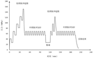
Fig. 1 is a schematic view of a pressure change curve in fracturing construction in embodiment 1 of the present invention.
Fig. 2 is a schematic view of a pressure change curve in fracturing construction in embodiment 2 of the present invention.
Fig. 3 is a schematic view of a pressure change curve in fracturing construction in embodiment 3 of the present invention.
Fig. 4 is a schematic structural diagram of a pulse hydraulic energy generating tool with an underseal.
FIG. 5 is a schematic view of a configuration of a pulse hydraulic energy generating tool with a bottom seal respectively matched with a casing and a coiled tubing.
Fig. 6 is a schematic diagram showing the rotor, stator, and liquid ejecting apparatus of the pulse hydraulic energy generating tool with the bottom seal.
Description of reference numerals: 2-rotary joint, 3-rotary piece, 4-fixed piece, 5-screw shell, 6-rotor, 7-stator, 8-spray cavity, 9-nozzle, 11-channel, 14-flow dividing structure, 15-coiled tubing, 16-gap.
Detailed Description
For a better understanding of the technical features, objects and advantages of the present invention, reference will now be made in detail to the following embodiments of the present invention, which are illustrated in the accompanying drawings, and the accompanying drawings are included to illustrate the present invention.
The well depth of a certain well is 6050m, the horizontal section is 1500 in length and the vertical depth is 4185m, the horizontal section is 4550m to 6050m, the fracturing is divided into 25 sections, each section is 60m on average, each section is perforated for 8 clusters, the total maximum discharge capacity of the first fluid and the second fluid is 20m3And/min, fracturing construction is carried out by adopting three different modes, specifically shown in examples 1, 2 and 3. The first fluid and the second fluid are both fracturing fluids.
Example 1 fracturing using the method of the invention
The method specifically comprises the following steps:
step 1, surface and borehole preparation: preparing a first ground fracturing truck group, a second ground fracturing truck group, a matched tool and fracturing fluid, and carrying out drifting and well washing operations.
And 4, generating main cracks and a small amount of complex seam nets: after the first fluid is pumped for 3-10 min from the step 3, the first fluid discharge is increased to 2.0-5.0 m3Min, the second fluid discharge capacity is 8.0-15.0 m3And/min, pumping 10% of fracturing fluid of the fracturing section.
And 7, fracturing the second section and the subsequent sections: repeating the steps 2, 3, 4, 5 and 6; and in the period, according to the field working condition, replacing the underground pulse hydraulic energy generation tool in time when 3-5 sections of fracturing are completed.
The pressure change of the fracturing job is shown in figure 1.
The implementation effect shows that through analysis of fracture form and complexity, the longest fracture length of fracturing modification in the embodiment is 250-350 m, the fracture width is 30-120 m, and the fracture height is 40-60 m, so that the modification volume SRV is 3200 ten thousand square, which is about 500 ten thousand square higher than that of the conventional similar hydraulic fracturing method, the fracture complexity is obviously increased, and the fracture length is increased by 10-30 m.
Example 2 fracturing using the method of the invention
The method specifically comprises the following steps:
step 1, surface and borehole preparation: preparing a first ground fracturing truck group, a second ground fracturing truck group, a matched tool and fracturing fluid, and carrying out drifting and well washing operations.
And 4, generating main cracks and a small amount of complex seam nets: increasing the discharge capacity of the second fluid to 8.0-15.0 m3Min, the first fluid maintains the discharge capacity of 2.0-5.0 m3And/min, pumping 15% of fracturing fluid of the fracturing section to generate a main fracture and a small amount of complex fracture network.
And 7, fracturing the second section and the subsequent sections: repeating the steps 2, 3, 4, 5, 6 and 7; and in the period, according to the field working condition, replacing the underground pulse hydraulic energy generation tool in time when 3-5 sections of fracturing are completed.
The pressure change of the fracturing job is shown in figure 2.
The implementation effect shows that through fracture form and complexity analysis, the longest fracture length of fracturing modification in the embodiment is 240-350 m, the fracture width is 40-120 m, and the fracture height is 40-60 m, so that the modification volume SRV3100 ten thousand is realized, the modification volume SRV is improved by about 400 ten thousand compared with that of a conventional similar hydraulic fracturing method, the fracture complexity is obviously increased, and the fracture length is averagely increased by 10-30 m.
Example 3 fracturing using the method of the invention
The method comprises the following steps:
step 1, surface and borehole preparation: preparing a first ground fracturing truck group, a second ground fracturing truck group, a matched tool and fracturing fluid, and carrying out drifting and well washing operations.
Step 4, generating main cracks and small amount of cracksAnd (3) sewing a net: after the first fluid is pumped for 3-10 min from the step 3, the first fluid discharge is increased to 2.0-5.0 m3Min, the second fluid discharge capacity is 8.0-15.0 m3And/min, pumping 20% of fracturing fluid of the fracturing section to generate a main fracture and a small amount of complex fracture network.
And 7, fracturing the second section and the subsequent sections: repeating the steps 2, 3, 4, 5 and 6; and in the period, according to the field working condition, replacing the underground pulse hydraulic energy generation tool in time when 3-5 sections of fracturing are completed.
The pressure change for the fracturing job is shown in figure 3.
The implementation effect shows that through analysis of fracture form and complexity, the longest fracture length of fracturing modification in the embodiment is 260-360 m, the fracture width is 40-125 m, and the fracture height is 40-62 m, so that the modification volume SRV is 3250 ten thousand square, which is about 550 ten thousand square higher than that of the conventional similar hydraulic fracturing method, the fracture complexity is obviously increased, and the fracture length is averagely increased by 10-40 m.
The embodiments described above describe only some of the one or more embodiments of the present invention, but those skilled in the art will recognize that the invention can be embodied in many other forms without departing from the spirit or scope thereof. Accordingly, the present examples and embodiments are to be considered as illustrative and not restrictive, and various modifications and substitutions may be made therein without departing from the spirit and scope of the present invention as defined by the appended claims.
Claims (10)
1. A stepped pulse circulation temporary plugging complex fracture network fracturing method for a deep low-permeability reservoir is characterized by comprising the following steps:
step 1, preparing a borehole: carrying out drifting and well washing operations;
step 2, perforation operation: the connected underground pulse hydraulic energy generating tool is lowered to a specified perforation section by using a continuous oil pipe, and a first ground fracturing truck set is used for providing 80-140 MPa pressure and 0.2-1.0 m for the underground pulse hydraulic energy generating tool with the bottom seal3Forming ultrahigh pressure pulse abrasive water jet in the first fluid with the displacement of/min underground to finish perforation; the first fluid is a fracturing fluid;
step 3, reservoir fracturing: pumping 1.0-3.0 m between the coiled tubing and the annular space of the casing by using a second ground fracturing truck set3Mixing the first fluid and the second fluid by using a/min low-displacement high-pressure second fluid, and generating high-pressure pulse hydraulic energy by using a downhole pulse hydraulic energy generating tool in a matching manner to complete reservoir rock fracture; the second fluid is fracturing fluid;
and 4, generating main cracks and a small amount of complex seam nets: increasing the discharge capacity of the second fluid to 8.0-15.0 m3Min, increasing the first fluid discharge to 2.0-5.0 m3Pumping 10-20% of fracturing fluid of the fracturing section to generate a main fracture and a small amount of complex fracture network;
step 5, further expanding and sanding the complex seam net: adding proppant in the second fluid in a stepped manner according to a preset sand adding ratio, determining and controlling the discharge capacity and pressure of the first fluid according to the formation fracture and fracture extension pressure, and controlling the sand adding ratio within 15% of the volume ratio; or stopping the injection of the first fluid, and maintaining the discharge capacity of the second fluid at 8.0-15.0 m according to the preset sand adding ratio3Step-wise adding proppant in the/min, wherein the sand adding ratio is controlled within 15% of the volume ratio;
step 6, temporarily blocking and further forming a seam net: continuing injecting the first fluid, adding the mixed degradable temporary plugging agent and degradable particles into the second fluid, wherein the volume ratio of the degradable particles to the degradable temporary plugging agent is 1: 1-2: 1, the particle size of the degradable particles is larger than that of the degradable temporary plugging agent, repeating the steps 3, 4 and 5 after temporary plugging is finished, and finishing the first-stage fracturing until the pump finishes injecting the propping agent and fracturing fluid required by the first designated perforation section;
and 7, fracturing the second section and the subsequent sections: repeating the steps 2, 3, 4, 5 and 6; and in the period, according to the field working condition, replacing the underground pulse hydraulic energy generation tool in time when 3-5 sections of fracturing are completed.
2. The deep hypotonic reservoir stepped pulse circulation plugging complex fracture network fracturing method of claim 1, wherein in the step 2, the downhole pulse hydraulic energy generating tool is a pulse hydraulic energy generating tool with a bottom seal.
3. The deep hypotonic reservoir stepped pulse circulation plugging complex fracture network fracturing method of claim 1, wherein in the step 2, the downhole pulse hydraulic energy generation tool is driven by the first fluid provided by the first fracturing truck group, and the first fluid pressure is further increased to 200-250 MPa by the spraying cavity configured by the tool.
4. The deep hypotonic reservoir stepped pulse circulation temporary plugging complex fracture network fracturing method of claim 1, wherein in the steps 3, 4 and 5, a first surface fracturing truck group is controlled and a downhole pulse hydraulic energy generating tool is replaced, low, medium and high frequency three types with the frequency of 0.001-0.1 HZ, 0.01-1 HZ and 0.1-10 HZ are provided, and the discharge capacity is 1.0-5.0 m3First fluid,/min.
5. The deep hypotonic reservoir stepped pulse circulation plugging complex fracture network fracturing method of claim 1, wherein in the step 5, the sand adding ratio in the second fluid is controlled to be 5-12% by volume.
6. The deep hypotonic reservoir stepped pulse circulation plugging complex fracture network fracturing method of claim 1, wherein in the steps 2, 3, 4 and 5, according to the fracture of the stratum and the complex fracture network extending pressure, the first fluid is closed or the pulsed hydraulic energy fluid with specific frequency and pressure is generated in real time by adjusting pumping parameters of the first surface fracturing truck group and being matched with a downhole pulsed hydraulic energy generating tool.
7. The deep hypotonic reservoir stepped pulse circulation temporary plugging complex fracture network fracturing method of claim 1, wherein in the step 6, the particle size of the degradable temporary plugging agent is 60-140 meshes in various specifications, and is 60-80% of the total mass of the degradable temporary plugging agent and the degradable particles; the particle size of the degradable particles is 2-14 mm and is 20-40% of the total mass of the degradable temporary plugging agent and the degradable particles.
8. The deep hypotonic reservoir stepped pulse circulation plugging complex fracture network fracturing method of claim 7, wherein in the step 6, the particle size of the degradable plugging agent is at least one of 60, 80, 100, 120 or 140 meshes.
9. The deep hypotonic reservoir stepped pulse circulation plugging complex fracture network fracturing method of claim 7, wherein in step 6, the degradable particles have a particle size of at least one of 2, 4, 6, 8, 10, 12 or 14 mm.
10. The deep hypotonic reservoir stepped pulse circulation temporary plugging complex fracture network fracturing method of claim 1, wherein in step 7, when the downhole pulse hydraulic energy generating tool is replaced, the downhole pulse hydraulic energy generating tool needs to be unsealed, and then the downhole pulse hydraulic energy generating tool needs to be taken to the ground by using a coiled tubing.
Priority Applications (1)
| Application Number | Priority Date | Filing Date | Title |
|---|---|---|---|
| CN202011308690.9A CN112253073A (en) | 2020-11-20 | 2020-11-20 | Stepped pulse circulation temporary plugging complex fracture network fracturing method for deep low-permeability reservoir |
Applications Claiming Priority (1)
| Application Number | Priority Date | Filing Date | Title |
|---|---|---|---|
| CN202011308690.9A CN112253073A (en) | 2020-11-20 | 2020-11-20 | Stepped pulse circulation temporary plugging complex fracture network fracturing method for deep low-permeability reservoir |
Publications (1)
| Publication Number | Publication Date |
|---|---|
| CN112253073A true CN112253073A (en) | 2021-01-22 |
Family
ID=74224884
Family Applications (1)
| Application Number | Title | Priority Date | Filing Date |
|---|---|---|---|
| CN202011308690.9A Pending CN112253073A (en) | 2020-11-20 | 2020-11-20 | Stepped pulse circulation temporary plugging complex fracture network fracturing method for deep low-permeability reservoir |
Country Status (1)
| Country | Link |
|---|---|
| CN (1) | CN112253073A (en) |
Cited By (4)
| Publication number | Priority date | Publication date | Assignee | Title |
|---|---|---|---|---|
| CN113464113A (en) * | 2021-08-16 | 2021-10-01 | 中国石油大学(北京) | Device, system and method for forming artificial complex seam net |
| CN115217457A (en) * | 2021-04-21 | 2022-10-21 | 中国石油化工股份有限公司 | Resonant pulse pressure wave fracturing method and system with same frequency as target layer |
| CN115749713A (en) * | 2022-10-14 | 2023-03-07 | 中国矿业大学 | Rock stratum frequency conversion pulse fracture network fracturing method and equipment |
| CN116877067A (en) * | 2023-07-18 | 2023-10-13 | 重庆地质矿产研究院 | Method for predicting hydraulic fracturing generated cracks and swept area fluid pressure |
Citations (10)
| Publication number | Priority date | Publication date | Assignee | Title |
|---|---|---|---|---|
| US4718490A (en) * | 1986-12-24 | 1988-01-12 | Mobil Oil Corporation | Creation of multiple sequential hydraulic fractures via hydraulic fracturing combined with controlled pulse fracturing |
| US5228510A (en) * | 1992-05-20 | 1993-07-20 | Mobil Oil Corporation | Method for enhancement of sequential hydraulic fracturing using control pulse fracturing |
| CN103615228A (en) * | 2013-11-26 | 2014-03-05 | 中国石油天然气股份有限公司 | Temporary plugging and fracturing process in degradable fiber clearance |
| CN103953323A (en) * | 2014-05-08 | 2014-07-30 | 西南石油大学 | Hydraulic fracturing technology for horizontal well with fractures |
| CN104929605A (en) * | 2015-06-26 | 2015-09-23 | 重庆地质矿产研究院 | Underground hydraulic pulse staged fracturing and permeability increasing device and method |
| CN105649594A (en) * | 2015-12-31 | 2016-06-08 | 中国石油天然气股份有限公司 | Method for maintaining flow conductivity of seams near wellbore area |
| CN105649593A (en) * | 2015-12-31 | 2016-06-08 | 中国石油天然气股份有限公司 | Method for maintaining flow conductivity of multi-slit fracturing seams in horizontal well section |
| CN105672970A (en) * | 2015-12-31 | 2016-06-15 | 中国石油天然气股份有限公司 | Method for realizing temporary plugging redirecting multiple crack fracturing inside horizontal well section |
| CN109184655A (en) * | 2018-11-21 | 2019-01-11 | 重庆地质矿产研究院 | Coiled tubing dragging pulse hydraulic fracturing tool with bottom setting and method |
| US20190024489A1 (en) * | 2015-09-23 | 2019-01-24 | Halliburton Energy Services, Inc. | Enhancing complex fracture geometry in subterranean formations, net pressure pulsing |
-
2020
- 2020-11-20 CN CN202011308690.9A patent/CN112253073A/en active Pending
Patent Citations (10)
| Publication number | Priority date | Publication date | Assignee | Title |
|---|---|---|---|---|
| US4718490A (en) * | 1986-12-24 | 1988-01-12 | Mobil Oil Corporation | Creation of multiple sequential hydraulic fractures via hydraulic fracturing combined with controlled pulse fracturing |
| US5228510A (en) * | 1992-05-20 | 1993-07-20 | Mobil Oil Corporation | Method for enhancement of sequential hydraulic fracturing using control pulse fracturing |
| CN103615228A (en) * | 2013-11-26 | 2014-03-05 | 中国石油天然气股份有限公司 | Temporary plugging and fracturing process in degradable fiber clearance |
| CN103953323A (en) * | 2014-05-08 | 2014-07-30 | 西南石油大学 | Hydraulic fracturing technology for horizontal well with fractures |
| CN104929605A (en) * | 2015-06-26 | 2015-09-23 | 重庆地质矿产研究院 | Underground hydraulic pulse staged fracturing and permeability increasing device and method |
| US20190024489A1 (en) * | 2015-09-23 | 2019-01-24 | Halliburton Energy Services, Inc. | Enhancing complex fracture geometry in subterranean formations, net pressure pulsing |
| CN105649594A (en) * | 2015-12-31 | 2016-06-08 | 中国石油天然气股份有限公司 | Method for maintaining flow conductivity of seams near wellbore area |
| CN105649593A (en) * | 2015-12-31 | 2016-06-08 | 中国石油天然气股份有限公司 | Method for maintaining flow conductivity of multi-slit fracturing seams in horizontal well section |
| CN105672970A (en) * | 2015-12-31 | 2016-06-15 | 中国石油天然气股份有限公司 | Method for realizing temporary plugging redirecting multiple crack fracturing inside horizontal well section |
| CN109184655A (en) * | 2018-11-21 | 2019-01-11 | 重庆地质矿产研究院 | Coiled tubing dragging pulse hydraulic fracturing tool with bottom setting and method |
Cited By (6)
| Publication number | Priority date | Publication date | Assignee | Title |
|---|---|---|---|---|
| CN115217457A (en) * | 2021-04-21 | 2022-10-21 | 中国石油化工股份有限公司 | Resonant pulse pressure wave fracturing method and system with same frequency as target layer |
| CN113464113A (en) * | 2021-08-16 | 2021-10-01 | 中国石油大学(北京) | Device, system and method for forming artificial complex seam net |
| CN115749713A (en) * | 2022-10-14 | 2023-03-07 | 中国矿业大学 | Rock stratum frequency conversion pulse fracture network fracturing method and equipment |
| WO2024077842A1 (en) * | 2022-10-14 | 2024-04-18 | 中国矿业大学 | Rock stratum fracturing method and equipment using variable-frequency pulse fracture network |
| CN116877067A (en) * | 2023-07-18 | 2023-10-13 | 重庆地质矿产研究院 | Method for predicting hydraulic fracturing generated cracks and swept area fluid pressure |
| CN116877067B (en) * | 2023-07-18 | 2024-03-12 | 重庆地质矿产研究院 | Method for predicting hydraulic fracturing generated cracks and swept area fluid pressure |
Similar Documents
| Publication | Publication Date | Title |
|---|---|---|
| CN112253073A (en) | Stepped pulse circulation temporary plugging complex fracture network fracturing method for deep low-permeability reservoir | |
| US7882895B2 (en) | Method for impulse stimulation of oil and gas well production | |
| US7571766B2 (en) | Methods of fracturing a subterranean formation using a jetting tool and a viscoelastic surfactant fluid to minimize formation damage | |
| RU2567877C2 (en) | Method for efficiency improvement in injection and intensification of oil and gas production | |
| CA2560611C (en) | Methods of isolating hydrajet stimulated zones | |
| US5228510A (en) | Method for enhancement of sequential hydraulic fracturing using control pulse fracturing | |
| US8082989B2 (en) | Method for impulse stimulation of oil and gas well production | |
| CN103080469B (en) | The method of unconventional gas reservoir simulation is carried out for the stress off-load strengthening fracture network connectedness | |
| CN109184655B (en) | Coiled tubing dragging pulse hydraulic fracturing tool with bottom setting and method | |
| US20090178801A1 (en) | Methods for injecting a consolidation fluid into a wellbore at a subterranian location | |
| MXPA02009416A (en) | System and method for fracturing a subterranean well formation for improving hydrocarbon production. | |
| CN105464638A (en) | Coal bed gas well pulse radial drilling and double-pulsating hydrofracturing method | |
| RU2078200C1 (en) | Method for development of oil formation | |
| CN106761650A (en) | Oil, many microcrack pressure break block releasing techniques of well | |
| CN111827954B (en) | Continuous pulse hydraulic fracturing system and method | |
| WO2018032086A1 (en) | Fracture length increasing method | |
| CN112324412A (en) | Method for forming complex seam net through volume fracturing | |
| CN112443305B (en) | Horizontal well fracturing method for promoting high fracture extension through twice acid injection and temporary plugging among clusters | |
| Gottschling et al. | Nitrogen gas and sand: a new technique for stimulation of Devonian shale | |
| Ahmed et al. | Adaptation of Technologies Making Clean out Operations Environment Friendly and Cost Effective-Converting Failure into Success Using New Type of Fluidic Oscillator | |
| CN214145451U (en) | Composite blockage removing equipment for oil-water well | |
| RU2283945C1 (en) | Method for hydrocarbon deposit development at later stage | |
| CN206972212U (en) | A kind of double vibration source low-frequency high-power vibrational systems in underground | |
| Browne et al. | Proppant flowback control in deviated shallow Gas Wells | |
| CN113622889B (en) | Radial well volume fracturing method |
Legal Events
| Date | Code | Title | Description |
|---|---|---|---|
| PB01 | Publication | ||
| PB01 | Publication | ||
| SE01 | Entry into force of request for substantive examination | ||
| SE01 | Entry into force of request for substantive examination |