CN112236183A - Medical catheter - Google Patents
Medical catheter Download PDFInfo
- Publication number
- CN112236183A CN112236183A CN201980037946.6A CN201980037946A CN112236183A CN 112236183 A CN112236183 A CN 112236183A CN 201980037946 A CN201980037946 A CN 201980037946A CN 112236183 A CN112236183 A CN 112236183A
- Authority
- CN
- China
- Prior art keywords
- catheter
- distal
- outer sheath
- proximal
- marker band
- Prior art date
- Legal status (The legal status is an assumption and is not a legal conclusion. Google has not performed a legal analysis and makes no representation as to the accuracy of the status listed.)
- Pending
Links
Images


Classifications
-
- A—HUMAN NECESSITIES
- A61—MEDICAL OR VETERINARY SCIENCE; HYGIENE
- A61M—DEVICES FOR INTRODUCING MEDIA INTO, OR ONTO, THE BODY; DEVICES FOR TRANSDUCING BODY MEDIA OR FOR TAKING MEDIA FROM THE BODY; DEVICES FOR PRODUCING OR ENDING SLEEP OR STUPOR
- A61M25/00—Catheters; Hollow probes
- A61M25/01—Introducing, guiding, advancing, emplacing or holding catheters
- A61M25/0105—Steering means as part of the catheter or advancing means; Markers for positioning
- A61M25/0108—Steering means as part of the catheter or advancing means; Markers for positioning using radio-opaque or ultrasound markers
-
- A—HUMAN NECESSITIES
- A61—MEDICAL OR VETERINARY SCIENCE; HYGIENE
- A61M—DEVICES FOR INTRODUCING MEDIA INTO, OR ONTO, THE BODY; DEVICES FOR TRANSDUCING BODY MEDIA OR FOR TAKING MEDIA FROM THE BODY; DEVICES FOR PRODUCING OR ENDING SLEEP OR STUPOR
- A61M25/00—Catheters; Hollow probes
- A61M25/01—Introducing, guiding, advancing, emplacing or holding catheters
- A61M25/0105—Steering means as part of the catheter or advancing means; Markers for positioning
-
- A—HUMAN NECESSITIES
- A61—MEDICAL OR VETERINARY SCIENCE; HYGIENE
- A61L—METHODS OR APPARATUS FOR STERILISING MATERIALS OR OBJECTS IN GENERAL; DISINFECTION, STERILISATION OR DEODORISATION OF AIR; CHEMICAL ASPECTS OF BANDAGES, DRESSINGS, ABSORBENT PADS OR SURGICAL ARTICLES; MATERIALS FOR BANDAGES, DRESSINGS, ABSORBENT PADS OR SURGICAL ARTICLES
- A61L29/00—Materials for catheters, medical tubing, cannulae, or endoscopes or for coating catheters
- A61L29/04—Macromolecular materials
- A61L29/049—Mixtures of macromolecular compounds
-
- A—HUMAN NECESSITIES
- A61—MEDICAL OR VETERINARY SCIENCE; HYGIENE
- A61M—DEVICES FOR INTRODUCING MEDIA INTO, OR ONTO, THE BODY; DEVICES FOR TRANSDUCING BODY MEDIA OR FOR TAKING MEDIA FROM THE BODY; DEVICES FOR PRODUCING OR ENDING SLEEP OR STUPOR
- A61M25/00—Catheters; Hollow probes
- A61M25/0043—Catheters; Hollow probes characterised by structural features
- A61M25/0045—Catheters; Hollow probes characterised by structural features multi-layered, e.g. coated
-
- A—HUMAN NECESSITIES
- A61—MEDICAL OR VETERINARY SCIENCE; HYGIENE
- A61M—DEVICES FOR INTRODUCING MEDIA INTO, OR ONTO, THE BODY; DEVICES FOR TRANSDUCING BODY MEDIA OR FOR TAKING MEDIA FROM THE BODY; DEVICES FOR PRODUCING OR ENDING SLEEP OR STUPOR
- A61M25/00—Catheters; Hollow probes
- A61M25/0067—Catheters; Hollow probes characterised by the distal end, e.g. tips
- A61M25/0068—Static characteristics of the catheter tip, e.g. shape, atraumatic tip, curved tip or tip structure
-
- A—HUMAN NECESSITIES
- A61—MEDICAL OR VETERINARY SCIENCE; HYGIENE
- A61M—DEVICES FOR INTRODUCING MEDIA INTO, OR ONTO, THE BODY; DEVICES FOR TRANSDUCING BODY MEDIA OR FOR TAKING MEDIA FROM THE BODY; DEVICES FOR PRODUCING OR ENDING SLEEP OR STUPOR
- A61M25/00—Catheters; Hollow probes
- A61M2025/0004—Catheters; Hollow probes having two or more concentrically arranged tubes for forming a concentric catheter system
-
- A—HUMAN NECESSITIES
- A61—MEDICAL OR VETERINARY SCIENCE; HYGIENE
- A61M—DEVICES FOR INTRODUCING MEDIA INTO, OR ONTO, THE BODY; DEVICES FOR TRANSDUCING BODY MEDIA OR FOR TAKING MEDIA FROM THE BODY; DEVICES FOR PRODUCING OR ENDING SLEEP OR STUPOR
- A61M25/00—Catheters; Hollow probes
- A61M2025/0008—Catheters; Hollow probes having visible markings on its surface, i.e. visible to the naked eye, for any purpose, e.g. insertion depth markers, rotational markers or identification of type
-
- A—HUMAN NECESSITIES
- A61—MEDICAL OR VETERINARY SCIENCE; HYGIENE
- A61M—DEVICES FOR INTRODUCING MEDIA INTO, OR ONTO, THE BODY; DEVICES FOR TRANSDUCING BODY MEDIA OR FOR TAKING MEDIA FROM THE BODY; DEVICES FOR PRODUCING OR ENDING SLEEP OR STUPOR
- A61M25/00—Catheters; Hollow probes
- A61M25/01—Introducing, guiding, advancing, emplacing or holding catheters
- A61M25/0105—Steering means as part of the catheter or advancing means; Markers for positioning
- A61M2025/0166—Sensors, electrodes or the like for guiding the catheter to a target zone, e.g. image guided or magnetically guided
-
- A—HUMAN NECESSITIES
- A61—MEDICAL OR VETERINARY SCIENCE; HYGIENE
- A61M—DEVICES FOR INTRODUCING MEDIA INTO, OR ONTO, THE BODY; DEVICES FOR TRANSDUCING BODY MEDIA OR FOR TAKING MEDIA FROM THE BODY; DEVICES FOR PRODUCING OR ENDING SLEEP OR STUPOR
- A61M25/00—Catheters; Hollow probes
- A61M25/0043—Catheters; Hollow probes characterised by structural features
- A61M25/005—Catheters; Hollow probes characterised by structural features with embedded materials for reinforcement, e.g. wires, coils, braids
- A61M25/0052—Localized reinforcement, e.g. where only a specific part of the catheter is reinforced, for rapid exchange guidewire port
Abstract
A catheter (100) comprising an elongated body (102) comprising: a proximal portion comprising a proximal end; and a distal tip portion. The distal tip portion may include a lining (104) and a marker band (154) circumferentially surrounding the lining. The distal tip portion may further include: an outer sheath (106) circumferentially surrounding a first portion of the liner and terminating proximal to a proximal end of the marker band; and a sharp outer sheath circumferentially surrounding the second portion of the liner and the marker band. The tip outer sheath extends distally beyond the marker band distal end to a distal tip of the elongate body, and a proximal end of the tip outer sheath may be laterally adjacent a distal end of the outer sheath.
Description
This application claims the benefit of U.S. provisional patent application No. 62/680,792 entitled "MEDICAL CATHETER (medical catheter)" filed on 5.6.2018 and U.S. provisional patent application No. 62/848,926 entitled "MEDICAL CATHETER (medical catheter)" filed on 16.5.2019.
Technical Field
The present disclosure relates to a medical catheter.
Background
Medical catheters defining at least one lumen have been proposed for use in various medical procedures. For example, in certain instances, medical catheters may be used to deliver medical devices and/or compositions within the vasculature of a patient.
Disclosure of Invention
In certain aspects, the present disclosure describes example catheters, each catheter including a pushing assembly and an elongate body, the elongate body including: a liner defining an access port into a cavity of the elongated body; and an outer sheath. The pusher assembly may include an elongate member and an anchor member positioned at a distal end of the elongate member. The elongate member is relatively rigid such that the pusher assembly may be configured to facilitate introduction of the catheter into the vasculature of a patient. A portion of the pusher assembly including the anchor member may be positioned between adjacent portions of the inner liner and the outer sheath distal to the access port when the pusher assembly is assembled with the elongate body. Proximal to the access port, a portion of the push assembly may be positioned outside of adjacent portions of the inner liner and the outer sheath. In some embodiments, the proximal portion of the pusher assembly may be positioned entirely outside of the inner liner and the outer jacket. In some embodiments, the anchor member may have a partial ring shape and a beveled distal edge, and may extend partially around the outer periphery of the liner.
In some embodiments, the catheter system includes an outer catheter, and the catheter including the pusher assembly may be an inner catheter that may be introduced into the vasculature of a patient through a lumen of the outer catheter. The elongate body may be configured to protrude from a distal opening of the outer catheter to extend through a severe tortuosity or calcification within a body vessel. The elongated body may have a smaller radial profile and may be more flexible than the outer catheter so that it may be more easily navigated through severe tortuosity or calcification within a body vessel than the outer catheter. In some embodiments, the elongate body may include an atraumatic tip to minimize adverse interaction with patient tissue during advancement of the elongate body within a body vessel.
In some aspects, the present disclosure describes example catheters, each catheter including a distal tip portion configured to reduce an impact force between the distal tip of the catheter and a patient's tissue as the catheter is advanced through a patient's vasculature. The distal tip portion may include a configuration that reduces the effective stiffness of the tip as compared to a more proximal portion of the catheter. For example, the distal tip portion may include a tip outer sheath comprising a material or mixture of materials having a lower durometer than an outer sheath of a more proximal portion of the catheter. As another example, the liner may terminate proximal to the distal tip, thereby reducing the effective stiffness of the distal tip portion.
Clause 1: a catheter, the catheter comprising: an elongated body comprising: a proximal portion comprising a proximal end; and a distal tip portion, wherein the distal tip portion comprises: a liner; a marker band circumferentially surrounding the liner and extending from a marker band proximal end to a marker band distal end; an outer sheath circumferentially surrounding a first portion of the liner and terminating proximal to the marker band proximal end; and a tip outer sheath circumferentially surrounding the second portion of the liner and the marker band, wherein the tip outer sheath extends distally beyond the marker band distal end to a distal tip of the elongate body, and wherein a proximal end of the tip outer sheath is laterally adjacent a distal end of the outer sheath.
Clause 2: the catheter of clause 1, further comprising an elongate pushing member mechanically coupled to the proximal end of the elongate body.
Clause 3: the catheter of clauses 1 or 2, wherein the elongate body defines at least one lumen extending from adjacent or at the proximal end to adjacent or at the distal tip.
Clause 4: the catheter of any of clauses 1-3, wherein the liner extends to the distal tip of the elongate body.
Clause 5: the catheter of any of clauses 1-3, wherein the liner terminates distal to the marker band distal end and proximal to the distal tip.
Clause 6: the catheter of any of clauses 1-3, wherein the liner terminates proximal to the distal tip and near the marker band distal end.
Clause 7: the catheter of any of clauses 1-6, wherein the tip outer sheath extends between about 1.5mm to about 3.0mm distal of the marker band distal end.
Clause 8: the catheter of any of clauses 1-7, wherein the tip outer sheath extends between about 1.5mm to about 3.0mm proximal of the proximal end of the marker band.
Clause 9: the catheter of any of clauses 1-8, wherein the marker band defines a length between the marker band proximal end and the marker band distal end of about 0.5mm to about 1.2 mm.
Clause 10: the catheter of any of clauses 1-9, wherein the proximal end of the tip outer sheath laterally abuts the distal end of the outer sheath.
Clause 11: the catheter of any of clauses 1-10, wherein the proximal end of the tip outer sheath is bonded to the distal end of the outer sheath.
Clause 12: the catheter of any of clauses 1-11, wherein the tip outer sheath exhibits a lower durometer than the outer sheath.
Clause 13: the catheter of any of clauses 1-12, further comprising a reinforcing member circumferentially surrounding the liner, wherein the reinforcing member does not extend distally beyond the marker band distal end.
Clause 14: the catheter of clause 13, wherein the distal end of the reinforcing member overlaps the marker band.
Clause 15: the catheter of clause 13, wherein the distal end of the reinforcing member is proximal to the proximal end of the marker band.
Clause 16: the catheter of clause 13, wherein the distal end of the reinforcing member is substantially aligned with the proximal end of the marker band.
Clause 17: the catheter of any of clauses 13-16, wherein the reinforcing member comprises a coil.
Clause 18: the catheter of clause 17, wherein the proximal portion comprises the coil, wherein the coil defines a first pitch in the proximal portion, wherein the coil defines a second pitch in the distal tip portion, and wherein the second pitch is greater than the first pitch.
Clause 19: the catheter of any of clauses 1-18, further comprising a hydrophilic coating on the outer sheath and the tip outer sheath.
Clause 20: the catheter of any of clauses 1-19, wherein the outer sheath comprises a first poly (ether block amide), and wherein the tip outer sheath comprises a second, different poly (ether block amide).
Clause 21: the catheter of any of clauses 1-19, wherein the outer sheath comprises a mixture of a first poly (ether block amide) and a second poly (ether block amide), and wherein the tip outer sheath comprises a different third poly (ether block amide).
Clause 22: a catheter, the catheter comprising: an elongated body comprising: a proximal portion comprising a proximal end; and a distal tip portion, wherein the distal tip portion comprises: a liner; a marker band circumferentially surrounding the liner and extending from a marker band proximal end to a marker band distal end; a reinforcement member circumferentially surrounding the liner, wherein the reinforcement member does not extend distally beyond the marker band distal end; and an outer sheath circumferentially surrounding a first portion of the reinforcement member and terminating proximal to the proximal end of the marker band, wherein the liner terminates distal to the marker band or distal to the marker band distal end and proximal to the distal tip, and wherein the outer sheath is the only layer distal to the distal end of the liner.
Clause 23: the catheter of clause 22, further comprising an elongate pushing member mechanically coupled to the proximal end of the elongate body.
Clause 24: the catheter of clause 22 or 23, wherein the elongate body defines at least one lumen extending proximally from the proximal end to proximate the distal tip.
Clause 25: the catheter of any of clauses 22-24, wherein the liner terminates proximal to the distal tip and near the marker band distal end.
Clause 26: the catheter of any of clauses 22-25, wherein the outer sheath extends between about 1.5mm to about 3.0mm distal of the marker band distal end.
Clause 27: the catheter of any of clauses 22-26, wherein the marker band defines a length between about 0.5 to about 1.2mm between the marker band proximal end and the marker band distal end.
Clause 28: the catheter of any of clauses 22-27, wherein the distal end of the reinforcing member overlaps the marker band.
Clause 29: the catheter of any of clauses 22-27, wherein the distal end of the reinforcing member is proximal to the proximal end of the marker band.
Clause 30: the catheter of any of clauses 22-27, wherein the distal end of the reinforcing member is substantially aligned with the proximal end of the marker band.
Clause 31: the catheter of any of clauses 22-30, wherein the reinforcing member comprises a coil.
Clause 32: the catheter of clause 31, wherein the proximal portion comprises the coil, wherein the coil defines a first pitch in the proximal portion, wherein the coil defines a second pitch in the distal tip portion, and wherein the second pitch is greater than the first pitch.
Clause 33: the catheter of any of clauses 22-32, further comprising a hydrophilic coating on the outer sheath and the tip outer sheath.
Clause 34: a method of using the catheter of any of clauses 1-33.
Clause 35: a method of manufacturing the catheter of any of clauses 1-33.
The details of one or more aspects of the disclosure are set forth in the accompanying drawings and the description below. Other features, objects, and advantages of the techniques described in this disclosure will be apparent from the description and drawings, and from the claims.
Drawings
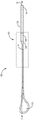
FIG. 1 is a conceptual side view of an example catheter including an elongate body, a pushing assembly, and a handle.
Fig. 2 is a conceptual cross-sectional view of a portion of the example catheter and outer catheter of fig. 1.
Fig. 3 is a conceptual cross-sectional view of an example elongate member of a pushing assembly of the catheter of fig. 1 and 2, taken along line 3-3 of fig. 2.
Fig. 4 is a conceptual cross-sectional view of an example elongate member of a pushing assembly of the catheter of fig. 1 and 2, taken along line 4-4 of fig. 2.
Fig. 5 is a conceptual cross-sectional view of an example elongate member of a pushing assembly of the catheter of fig. 1 and 2, taken along line 5-5 of fig. 2.
Fig. 6 is a conceptual cross-sectional view of the catheter of fig. 1 and 2, taken along line 6-6 of fig. 2.
Fig. 7A and 7B are conceptual cross-sectional views of embodiments of the catheter of fig. 1 and 2, taken along line 7-7 of fig. 2.
Fig. 8A and 8B are conceptual cross-sectional views of embodiments of the catheter of fig. 1 and 2 taken along line 8-8 of fig. 2.
Fig. 9 is a conceptual perspective view of the anchor member of fig. 1, 2, 6, 7A, 7B, 8A and 8B.
Fig. 10A and 10B are conceptual perspective views of the push assembly of fig. 1, 2, 6, 7A and 7B.
Fig. 11 is a conceptual perspective view of an example pusher assembly (e.g., the pusher assemblies of fig. 1, 2, 10A, and 10) that also includes a radiopaque band.
Fig. 12 and 13 are conceptual sectional views of example anchor members (e.g., the anchor members of fig. 1 and 2) having inner and/or outer surfaces defining non-semicircular surfaces.
Fig. 14 is a conceptual side view of an embodiment of an anchor member of the push assembly of fig. 2, 10A, and 10B and a distal portion of an elongate member of the push assembly of fig. 2, 10A, and 10B before the anchor member and elongate member are mechanically connected together to form the push assembly.
FIG. 15 is a conceptual side view of the push assembly of FIG. 14 after the anchor member and the elongate member are mechanically connected together to form the push assembly.
Fig. 16 is a conceptual perspective view of a portion of the embodiment of the elongated member of fig. 1, 2, 10A, 10B, and 11.
Fig. 17 is a flow chart illustrating an example method of assembling the example catheter shown in fig. 1 and 2.
Fig. 18-23 are conceptual side cross-sectional views of a distal tip section of an example catheter.
Fig. 24 is an image of an example tensile tester used to measure tip compressive force.
Fig. 25 is a graph of tip compression force measured in grams force for an example catheter constructed according to the present disclosure and three comparative examples.
Detailed Description
In some examples, a medical catheter ("catheter") described herein includes a pusher assembly and an elongate body including an inner liner and an outer sheath. The pusher assembly includes an elongate member (also referred to herein as a shaft) and an anchoring member at a distal end of the pusher assembly. In some embodiments, the pusher assembly includes only one anchoring member at the distal end of the pusher assembly, while in other embodiments, the pusher assembly includes a plurality of anchoring members. The anchor member is configured to facilitate attachment of the elongate member to the inner liner and outer jacket of the elongate body. The anchor member may be positioned at a distal end of the elongate member.
The outer sheath and the inner liner, alone or in combination with other elements, may form the elongate body, which may be a distal portion of the catheter. The elongate body defines at least one lumen through which a medical device (e.g., a catheter, guidewire, filter, stent delivery system, etc.), therapeutic agent, or other element can be introduced into a patient's vasculature or other tissue site. The liner may define an entry port into the cavity. At least a portion of the elongate member of the pusher assembly may extend proximally of the outer sheath and the liner. In embodiments where the catheter is part of an intravascular catheter system and is used in conjunction with an outer catheter, the elongate body of the catheter may be used to effectively extend the extent of the outer catheter. For example, the elongate body of the catheter may be pushed completely or partially through the lumen of the outer catheter until all or a portion of the elongate body extends beyond the distal end of the outer catheter, while the pushing assembly remains fully or partially within the lumen of the outer catheter. The pusher assembly has a lower profile than the elongate body, and therefore, the pusher assembly may occupy less space in the outer catheter lumen than the elongate body of the catheter. Thus, the pusher assembly may both facilitate the ability of the catheter to be pushed through the outer catheter and/or through the vasculature of the patient, while still being able to introduce a relatively large medical device through the outer catheter lumen to reach the lumen of the catheter.
In some embodiments, the catheters described herein may also assist in delivery to or through a diseased area or body. For example, the diseased area may include heavily tortuous and/or calcified portions, and the catheter may be more suitable than an outer catheter for navigating through such heavily tortuous and/or calcified portions due to its flexibility and lower profile. In some embodiments, the clinician may push the catheter out of the distal end of the outer catheter as the outer catheter approaches areas that would be difficult or impossible for the outer catheter to pass through. In some embodiments, the catheter is said to "telescope" out of the outer catheter when it is pushed out of the distal end of the outer catheter.
An elongate body including an inner liner and an outer sheath may define a proximal end. Distal of the proximal end, a portion of the pusher assembly including the anchor member may be positioned between the inner liner and the outer sheath. The anchor member may extend only partially around the periphery of the liner. Proximal to the proximal end of the elongate body, a portion of the pushing assembly proximal to the portion comprising the anchor member may be positioned outside of the outer sheath.
In some embodiments, the anchoring member may be configured to facilitate manufacture of the catheter. For example, the anchor may define a beveled distal edge to assist in anchor placement, including insertion and advancement of the anchor between the outer sheath and the liner. As another example, the anchor member may define a slot extending from the proximal end of the anchor member toward the distal end of the anchor member. The slot may facilitate attachment of the elongate member to the anchor member as the slot may be configured such that a distal end of the elongate member may be positioned at least partially within the slot and may be welded to the anchor. The slot may be configured such that welding material may be placed between the anchor member and the elongate member, for example in a gap within the slot between the anchor member and the elongate member when the distal end of the elongate member is at least partially positioned within the slot, such that the welding material does not increase the profile of the push assembly.
In some embodiments, the inner and/or outer surfaces of the anchor member may be non-semicircular surfaces, for example, surfaces defining a plurality of notches or corrugations and/or textured and/or etched surfaces. Such non-circular surfaces may help secure the anchor member between the inner liner and the outer sheath by providing a larger surface area that may be bonded to the inner liner and/or the outer sheath, including, for example, material backflow through the inner liner and/or the outer sheath.
In some embodiments, the catheter may include one or more radiopaque markers to facilitate visualization of the catheter during a medical procedure. One or more radiopaque markers may be positioned, for example, on the anchor member, on the elongate member, or in any suitable location or combination of locations to facilitate visualization and placement of the catheter relative to, for example, the outer catheter and/or the target tissue site. In some embodiments, the anchor is at least partially radiopaque and/or a radiopaque marker is positioned at or near an access port of the elongate body of the catheter. The placement of the radiopaque marker may enable the clinician to relatively quickly determine the location of the access port to the catheter lumen.
In some embodiments, the catheter may be configured to facilitate maneuverability. For example, the stiffness of the outer sheath may vary along its length, which may aid in the maneuverability of the catheter within the vasculature of a patient. As another example, a reinforcement member can be positioned between the inner liner and the outer sheath, can be distal and/or abutting the anchor member, and can aid in the strength and/or maneuverability of the catheter within the vasculature of the patient.
In some embodiments, the elongate member of the pusher assembly may be tapered in a distal direction to enable the distal portion of the elongate member to better approximate the profile of the anchor member. By tapering the elongate member rather than forming the entire elongate member to have a lower profile, the proximal portion of the elongate member may still be of a size and strength sufficient to push the catheter into the vasculature and/or of a size sufficient to be grasped by the user. In some of these embodiments, as well as others, the elongate member may be a solid member having a circular (e.g., circular) cross-section. That is, the elongate member may not define a central lumen or other opening in its cross-section.
In some embodiments, the catheter may facilitate differentiation from other devices and/or elements of the catheter used in conjunction with the catheter. For example, the sleeve may surround at least a portion of the elongate member, such as a portion proximal to the anchor member. In some embodiments, the sleeve may have a different color than the elongate member, elongate body, guidewire, and/or other devices used with the catheter to help visually distinguish the sleeve. The sleeve may also include other features to help facilitate use of the sleeve. For example, the sleeve may include one or more bands that include one or more partial cuts extending partially through the radial thickness of the sleeve and/or one or more indicia. In some embodiments, the sleeve may include a textured surface. In some embodiments, partial cuts and/or textured surfaces may facilitate tactile differentiation of the sleeve from other components. In some embodiments, one or more bands including one or more partial cuts and/or markings may aid in visual differentiation of the sleeve. The visual and/or tactile differentiation of the sleeve may enable the elongate member to be distinguished from other elements including, for example, an outer catheter, a guidewire, or other delivery devices or components used with the catheters described herein.
Fig. 1 is a conceptual side view of an example catheter 100 that includes an elongate body 102, a push assembly 108, and a handle 101. Fig. 2 is a conceptual cross-sectional view of a portion of the catheter 100 and the outer catheter 110 of fig. 1. The catheter 100 defines a longitudinal axis X. The elongate body 102 includes an inner liner 104 and an outer sheath 106. As shown in fig. 1, the elongate body 102 may define a proximal end 10 and a distal end 12.
In some embodiments, the catheter 100 may be part of an assembly that includes an outer catheter 110 defining a lumen 111 through which the catheter 100 may be introduced to access a distal target site within, for example, a patient's vasculature. Thus, at least a portion of the outer catheter 110 may be configured to surround the catheter 100. The outer catheter 110 may also define a distal opening 113, and in some embodiments, at least a portion of the catheter 100 may be configured to extend through the distal opening 113 and distally of the outer catheter 110, as shown in fig. 2. For example, the catheter 100 may be configured to extend out of the distal opening 113 of the outer catheter 110 to extend through severe tortuosity or calcification within a body vessel. The catheter 100 may have a smaller radial profile and may be more flexible than the outer catheter 110 so that it may be more easily navigated through severe tortuosity or calcifications within a body vessel than the outer catheter 110.
In some embodiments, the outer radial profile of the elongate body 102 of the catheter 100 may be similar to the radial shape and/or size of at least a distal portion of the lumen 111 of the outer catheter 110, such that the catheter 100 may fit relatively snugly inside the outer catheter 110 when the elongate body is at least partially within the outer catheter 110. This may help define a relatively smooth transition between the elongate body 102 and the outer catheter 110 when only a portion of the elongate body 102 extends distal of the distal opening 113 of the outer catheter 110 and another portion remains within the lumen 111 of the outer catheter 110, and/or when the proximal end of the elongate body 102 abuts the distal end of the outer catheter 110. Such a relatively smooth transition and/or snug fit may provide certain advantages. For example, fluid may be more easily transported through the lumen 111 of the outer catheter 110 and the lumen 105 of the elongate body 102 without leaking. As further examples, devices and/or other elements may be more easily advanced from lumen 111 of outer catheter 110 to lumen 105 of elongate body 102 because the transition between lumen 111 and lumen 105 may be relatively smooth such that the delivered components may not be captured in the transition from lumen 111 to lumen 105.
Although the catheter 100 is shown extending out of the distal opening 113 of the outer catheter 100 such that the proximal end 10 of the elongate body 102 is distal of the distal opening 113, in some medical procedures, the catheter 100 may be positioned relative to the outer catheter 110 such that the proximal end 10 of the elongate body 102 is proximate to the distal opening 113. For example, an access port 109 of the elongate body 102, described in further detail below, may be positioned within the lumen 111 of the outer catheter 110 such that an interventional medical device or another medical device may be introduced into the lumen 105 of the elongate body 102 from the lumen 111 of the outer catheter 110 without exiting the lumen 111.
In some embodiments, as shown in fig. 1, catheter 100 may include an atraumatic tip 14 to minimize adverse interaction with patient tissue during advancement of catheter 100 within a body vessel.
The elongate body 102 is configured to provide a delivery receptacle on the catheter 100 that can be extended distally of the outer catheter 110 to telescope out of the distal end of the outer catheter 110 and effectively extend the reach of the catheter within the vasculature of the patient and enable delivery of devices, agents, and/or any other suitable elements to a target site that may be difficult for the outer catheter 110 to reach. In some embodiments, the elongate body 102 may include an inner liner 104 and an outer jacket 106, which may provide multiple layers, between which a push assembly 108 may be inserted to attach the push assembly 108 to the elongate body 102. This may provide a relatively secure attachment between the pushing assembly 108 and the elongated body 102, and maintain relatively smooth outer and inner surfaces of the elongated body 102 at the portion of the elongated body 102 attached to the pushing assembly 108.
The inner liner 104 of the elongate body 102 defines a lumen 105 and the outer jacket 106 defines a lumen 107. In some embodiments, at least a portion of the liner 104 may be positioned within the lumen 107 of the outer sheath 106. In some embodiments, the liner 104 may extend the full length of the lumen 107 of the outer sheath 106. However, in other embodiments, the inner liner 104 may terminate before the distal end of the outer sheath 106 or may extend beyond the distal end of the outer sheath 106. Although the elongate body 102 is shown in fig. 1 as a tubular body, the elongate body 102 can have any suitable configuration.
The inner liner 104, alone or in combination with the outer jacket 106, may define an access port 109 into the lumen 105. The access port 109 can extend along the length of the elongate body 102 from a proximal end 138 to a distal end 140. In some embodiments, the access port 109 may be angled from the distal end 140 to the proximal end 138 due to the tapered shape of the elongate body 102. The access port 109 can be formed by skiving at least a portion of the portion 120 of the elongate body 102. In some embodiments, the access port 109 can have a length, measured along the longitudinal axis X from the proximal end 138 to the distal end 140, of about 2 centimeters (cm) to about 10cm (e.g., 2cm to 10cm or nearly 2cm to 10cm, within manufacturing tolerances), such as about 3.5cm to about 4.5cm or about 4 cm. It is believed that a tapered access port 109 having a relatively long length and angled from the distal end 140 to the proximal end 138 can facilitate smooth delivery of a medical device (e.g., an interventional medical device) into the lumen 105 of the elongate body 102 via the access port 109 by guiding the medical device into the lumen 105.
The pusher assembly 108 may be configured to enable a clinician to position the elongate body 102 relative to the outer catheter 110 and/or relative to the patient vasculature. For example, a proximal portion of the pusher assembly 108 may be configured to be grasped and moved by a clinician to position (e.g., distally or proximally advanced and/or rotated) the elongate body 102 within the vasculature of a patient. In some embodiments, the pusher assembly 108 may be used to advance the elongate body 102 relative to the outer catheter 110 to advance the elongate body 102 within the outer catheter 110 and/or to extend all or a portion of the elongate body 102 distal to the outer catheter 110 to access vasculature distal to the outer catheter 110. The pushing assembly 108 may comprise any suitable length. In some embodiments, the length of the pushing assembly 108 may be about 100cm to about 150cm, such as about 125cm, along the longitudinal axis X and measured from the distal end of the handle 101 to the distal end 128 of the anchor, or from the distal end of the handle 101 to the distal end of the elongate member 114. In some embodiments, the pushing assembly 108 includes an elongate member 114 and an anchor member 116. For clarity, a portion of the anchor member 116 is shown in phantom, which is located behind the liner 104 in the illustrated view. In some embodiments, the elongate member 114 may include a distal end 118, and the anchor member 116 may be positioned at the distal end 118 of the elongate member 114. In some embodiments, the pusher assembly 108 may not include any other anchoring member at the distal end 118 in addition to the anchoring member 116.
In some embodiments, at least a portion of the pusher assembly 108 is positioned between the inner liner 104 and at least an adjacent portion (e.g., a radially adjacent portion) of the outer jacket 106. For example, at least a portion of the push assembly 108 may be positioned radially inward of the outer sheath 106 and radially outward of the inner liner 104 such that the portion of the push assembly 108 is located between the outer sheath 106 and the inner liner 104. In some embodiments, the portion of the pushing assembly 108 between the inner liner 104 and the outer jacket 106 may have a length of about 4 cm. Positioning at least a portion of the pushing assembly 108 between portions of the inner liner 104 and the outer sheath 106 may help mechanically connect the pushing assembly 108 and the elongate body 102 to the elongate body 102 in a manner that enables the pushing assembly 108 to transmit a pushing force, and in some embodiments, a rotational force. Additionally, positioning at least a portion of the pusher assembly 108 between the inner liner 104 and the outer sheath 106 may enable the elongate body 102 to have relatively smooth inner and outer surfaces at the portion of the elongate body 102 attached to the pusher assembly 108.
In some embodiments, the elongated body 102 may include a tapered portion 120. For example, as shown in fig. 2, portions of the inner liner 104 and the outer sheath 106 corresponding to the tapered portion 120 of the elongate body 102 may taper in a proximal direction. Tapering the elongate body 102 at the tapered portion 120 may enable the elongate body 102 to be more easily retracted into the outer catheter 110. For example, during or after use of the catheter 100, a clinician may wish to retract at least a portion of the elongate body 102 within the outer catheter 110 by retracting the push assembly 108 proximally relative to the outer catheter 110. The tapered portion 120 may allow the elongate body 102 to enter the outer catheter 110 more smoothly.
Additionally, the tapered shape of the tapered portion 120 may be configured to facilitate attachment of the push assembly 108 to the elongate body 102. For example, the tapered shape may allow the anchor member 116 to support the access port 109 while also allowing the portion of the elongate member 114 proximate the anchor member 116 to be positioned between the inner liner 104 and the outer sheath 106, which may increase the bond tensile strength between the push assembly 108 and the elongate body 102. Where the length of the elongate member 114 positioned between the inner liner 104 and the outer sheath 106 is short, the bond tensile strength between the push assembly 108 and the elongate body 102 may be reduced. Thus, if only the anchor member 116 (and not the elongate member 114) is positioned between the liner 104 and the outer sheath 106, the bond tensile strength between the push assembly 108 and the elongate body 102 may be reduced. The reduced bond tensile strength may adversely affect the ability of the pushing assembly 108 to transmit pushing and/or rotational forces to the elongate body 102 without compromising the mechanical connection between the pushing assembly 108 and the elongate body 102.
Moreover, because the distal portion of the elongate member 114 may be relatively flexible (as compared to a more proximal portion of the elongate member 114), as described in further detail below, positioning the distal portion of the elongate member 114 between the liner 104 and the outer sheath 106 may help prevent the joint of the pusher assembly 108 and the elongate body 102 from having a desired stiffness.
In certain embodiments, a portion of the pusher assembly 108 is positioned between the inner liner 104 and an adjacent portion of the outer sheath 106 distal to the proximal end 10 of the elongate body 102. Proximal to the proximal end 10 of the elongate body 102, a portion of the pusher assembly 108 is positioned outside of the outer sheath 106 and the liner 104. The portion of the pusher assembly 108 positioned between the adjacent portions of the inner liner 104 and the outer jacket 106 may include an anchor member 116. The portion of the pusher assembly 108 positioned outside of the outer sheath 106 and the inner liner 104 may be located proximal to the portion positioned between the inner liner 104 and the adjacent portion of the outer sheath 106.
The anchor member 116 may have any suitable shape and size. In some embodiments, at least the outer surface of the anchor member 116 may define a partial ring shape, as shown in more detail below with reference to fig. 6-9. However, in other embodiments, the anchor member 116 may define other shapes. The partial ring shape of the anchor member 116 may provide one or more advantages. For example, the partial ring shape may provide support for the inner liner 104 and the outer jacket 106 to prevent proximal collapse of the inner liner 104 and the outer jacket 106, thereby helping to maintain an open state of the access port 109 into the lumen 105 defined by the inner lumen 104 so that other catheters or devices may be inserted into the lumen 105.
In some embodiments, and as described in further detail below with respect to fig. 6, the anchor members 116 may have an inner perimeter that is smaller than an outer perimeter of the liner 104, and the anchor members 116 may extend only partially around the outer perimeter of the liner 104. For example, the anchor members 116 may extend about 140 degrees to about 160 degrees around the circumference of the liner 104. More specifically, in some embodiments, the anchor members 116 may extend about 160 degrees around the circumference of the liner 104. In some embodiments, the anchor member 116 is radiopaque, and extending only partially around the periphery of the liner 104 may enable the anchor member 116 to indicate a rotational orientation (e.g., rotational position about the longitudinal axis X) of the elongate body 102 (e.g., access port 109) within the vasculature of the patient. This may enable the clinician to better position the catheter 100 relative to the outer catheter 110.
Additionally, extending only partially around the periphery of the liner 104 may enable the anchor members 116 to be positioned within the tapered portion 120 of the elongate body 102. This may enable the anchor member 116 to be positioned at the access port 109 to indicate its location, and may also enable the anchor member 116 to provide structural support for the tapered portions of the inner liner 104 and outer jacket 106. The full annular shape would not be located within the tapered portion 120 of the elongate body 102, but would need to be located distal of the tapered portion 120 and thus distal of the access port 109 in order to fit between the inner liner 104 and the outer sheath 106 without being exposed, and would therefore not include indicia indicating the location of the access port 109.
However, in some embodiments, as shown in FIG. 2, the proximal end of the anchor member 116 is positioned proximate to the distal end 140 of the access port 109. For example, the proximal end of the anchor member 116 can be aligned with the distal end 140 of the access port 109 such that the anchor member 116 is positioned entirely within the portion of the elongate body 102 defining the cross-section of a circular outer periphery. As another example, the proximal end of the anchor member 116 may not be precisely aligned with the distal end 140 of the access port 109, but rather may be within 4 millimeters (mm), such as within 2mm or less, of the distal end 140 of the access port 109 in the proximal or distal direction. In these embodiments, a substantial length of the anchor member 116 is positioned within a portion of the elongate body 102 defining a circular outer periphery in cross-section.
Such a partial ring shape of anchor member 116 may also be preferred over a full ring shape because it is less likely to bundle liner 104 during insertion of anchor member 116 between outer sheath 106 and liner 104 because anchor member 116 does not extend completely around the outer circumference of liner 104.
In some embodiments, the anchor member 116 may define a beveled distal edge 124. The beveled distal edge 124 may allow the anchor member 116 to be inserted and advanced between the liner 104 and the outer sheath 106 more easily than embodiments where the anchor member has a straight edge. For example, the beveled distal edge 124 may make it easier for the anchor member 116 to be inserted between the liner 104 and the outer sheath 106 by providing a narrow profile of the anchor member 116 at the distal end 128 that guides the anchor member 116 into the space between the liner 104 and the outer sheath 106. Additionally, the beveled distal edge 124 may provide a smooth distal profile of the anchor member 116 that results in less resistance to advancement of the anchor member 116 between and relative to the liner 104 and the outer sheath 106 as compared to a profile that includes straight edges and/or sharp corners (which may be more easily snagged on the liner 104 and/or the outer sheath 106).
The liner 104 may be formed of any suitable material, such as, but not limited to, Polytetrafluoroethylene (PTFE). In some embodiments, the outer jacket 106 may comprise one or more polymers. In some embodiments, the outer jacket 106 may have a hydrophilic coating. For example, the hydrophilic coating may be positioned on the entire outer surface of the outer sheath 106, or along only a portion of the outer sheath, such as only the distal-most portion of the outer sheath 106. In some embodiments, the hydrophilic coating is positioned over a distal-most portion of the outer sheath 106 of about 15cm to about 25cm (e.g., 15cm to 25cm within manufacturing tolerances allowed), such as about 20cm to about 22cm distal-most of the outer sheath 106, or about 21cm distal-most of the outer sheath 106, as measured from the distal end of the outer sheath 106, which in some embodiments may correspond to the distal end 12 of the elongate body 102.
In some embodiments, the outer sheath 106 may include multiple sections having different stiffnesses. For example, the outer sheath 106 may include a proximal section corresponding to the portion 136 of the catheter 100, and a distal section (shown in fig. 1) corresponding to the portion 129 of the catheter 100, which is distal to the proximal section. In some embodiments, the proximal section can be about 1cm to about 4cm long, such as about 2.5cm long or about 1.25cm long. In some embodiments, the distal section can be about 15cm to about 27cm long, such as about 24cm to about 26cm long, or about 25cm long. The length may be measured along the longitudinal axis X.
The distal section of the outer sheath 106 may have a different stiffness than the proximal section. For example, the distal section may have a stiffness greater than the stiffness of the proximal section. In other embodiments, the distal section may have a stiffness less than the proximal section. The outer sheath 106 having a more rigid proximal section (relative to the distal outer sheath section) can help maintain the integrity of the proximal portion of the inner lumen 105 of the elongate body 102, which can help introduce medical devices from the access port 109 into the lumen 105 without adversely affecting the navigability of the catheter 100 through the vasculature of a patient. For example, the outer sheath 106 having a more rigid proximal section can help the distal end 140 of the access port 109 and the proximal-most portion of the elongate body 102 resist deformation to help maintain lumen integrity.
The outer jacket 106 may include any suitable number of sections having any suitable stiffness according to particular needs. In some embodiments, sections of the outer sheath 106 may comprise different types of polymers, wherein the more rigid section comprises a more rigid polymer than the more flexible section comprising a softer polymer. In some embodiments, an outer sheath 106 having multiple sections with different stiffnesses may provide improved functionality of the outer sheath 106, including, for example, improved maneuverability of the outer sheath 106 through the vasculature. For example, the distal section may be less rigid than the proximal section, which may allow the distal section to have improved flexibility for navigation through the vasculature.
In some embodiments, the catheter 100 may also include a reinforcement member 126 positioned between a portion of the liner 104 and a portion of the outer sheath 106. For clarity, a portion of the reinforcement member 126 positioned behind the liner 104 in the illustrated view is shown in phantom. The reinforcing member 126 may be any suitable structure configured to provide structural support to the elongate body 102 and, in some embodiments, increase the structural integrity of the elongate body 102. For example, the reinforcement member 126 may include a metal coil, a metal braid, or a combination thereof. In some embodiments, the distal end 128 of the anchor member 116 may be positioned proximate to and spaced apart from the reinforcing member 126 such that a gap exists between the distal end 128 of the anchor member 116 and the proximal end 130 of the reinforcing member 126. Example gaps include, for example, gaps less than or equal to 4mm, such as gaps of about 2mm or less than 2mm, measured along the longitudinal axis X. In other embodiments, the anchor member 116 may contact (e.g., abut) the reinforcement member 126, e.g., the distal end 128 of the anchor member 116 may contact the proximal end 130 of the reinforcement member 126. In other embodiments, the anchor member 116 and the reinforcement member 126 may overlap in the longitudinal direction, for example, by a length of about 2mm or less, such as about 1mm or less.
The anchor member 116 at the distal end 118 of the elongate member 114 may increase the surface area of the distal portion of the push assembly 108 relative to embodiments including a push assembly that includes only the elongate member 114 without the anchor member 116, which may provide certain advantages. For example, the increased surface area at the distal portion of the pusher assembly 108 provided by the anchor member 116 may improve the tensile strength of the catheter 100 by enhancing the bond between the pusher assembly 108 and the elongate body 102. Additionally, as the catheter 100 is advanced through the vasculature of a patient, the increased surface area provided by the anchor member 116 at the distal portion of the pusher assembly 108 may help prevent the elongate member 114 from protruding through the outer sheath 106 when the elongate member 114 is compressed, i.e., when a pushing force is applied to the proximal portion of the elongate body 114. For example, in embodiments without the anchor member 116, the distal end 118 of the elongate member 114 may pierce the outer sheath 106 due to the relatively small surface area of the distal end 118 of the elongate member 114. However, the anchor member 116 helps distribute the thrust force and minimizes any pressure points at the distal end of the pushing assembly 108. Additionally, the anchor member 116 may help avoid bending of the distal end 118 of the elongate member 114 under the outer sheath 106 by providing reinforcement to the distal end 118 of the elongate member 114.
Fig. 3, 4, and 5 are conceptual cross-sectional views of an example elongate member 114 of the pushing assembly 108 of the catheter 100 of fig. 1 and 2 taken along lines 3-3, 4-4, and 5-5, respectively, in fig. 2. Although lines 3-3, 4-4, and 5-5 are shown in fig. 1 as intersecting various elements of catheter 100, fig. 3, 4, and 5 show only the cross-section of elongate member 114 for clarity. As shown, the elongate member 114 may taper in a distal direction. For example, in some embodiments and as shown in the illustrated embodiments, the maximum cross-sectional dimension of the elongated member 114 taken along line 5-5 may be less than the maximum cross-sectional dimension of the elongated member 114 taken along line 3-3 and the maximum cross-sectional dimension of the elongated member 114 taken along line 4-4. In some embodiments and as shown in the illustrated embodiments, the maximum cross-sectional dimension of the elongated member 114 taken along line 4-4 may be less than the maximum cross-sectional dimension of the elongated member 114 taken along line 3-3. The transitions between the cross-sections illustrated in fig. 3, 4 and 5 may be gradual, defined by discrete tapered sections, or defined by substantially constant tapered sections.
In some embodiments, a cross-section of a proximal portion of the elongate member 114, such as a cross-section taken along line 3-3, may be circular (e.g., circular). In some embodiments, the proximal portion of the elongate member 114 having a circular cross-section may comprise a proximal-most portion of the elongate member 114, which comprises the proximal end of the elongate member 114. Additionally, in some embodiments, the cross-section of the proximal portion of the elongate member 114 (the configuration of which may be represented by the cross-section taken along line 3-3) may be circular and solid (e.g., not hollow or defined by any lumen). An elongate member 114 having a proximal portion with a solid and circular cross-section may exhibit better thrust transmission along the catheter 110, e.g., the proximal portion may be hollow in cross-section and/or non-circular (e.g., rectangular) in cross-section relative to an elongate body having a proximal portion.
In some embodiments, the maximum cross-sectional dimension of the proximal portion of the elongate member 114, as shown at line 3-3, for example, is about 0.3mm to about 1mm, such as about 0.4mm to about 0.5 mm. However, in other embodiments, other cross-sectional dimensions of the elongated member 114 may be used.
In some embodiments, as in the illustrated embodiment, a portion of the elongated member 114 having a circular cross-section may be adjacent to a portion of the elongated member 114 having a D-shaped cross-section. The portion of the elongate member 114 having the D-shaped cross-section may define a smaller profile than a proximal portion of the elongate member 114 defining a circular (e.g., circular) cross-section, such that the portion of the elongate member 114 defining the D-shaped cross-section may define a "tapered" portion of the elongate member 114. For example, a cross-section of a medial and/or distal portion of the elongate member 114, such as a cross-section taken along line 4-4 or line 5-5, may be D-shaped. In these embodiments, one half of the cross-section of the elongated member 114 may be substantially flat (e.g., planar to the extent manufacturing tolerances permit), while the other longitudinal half of the elongated member 114 may be circular (e.g., semi-circular) in cross-section.
In embodiments where the distal portion of the elongate member 114 tapers in the distal direction, a first section of the distal portion may define a first D-shaped cross-section having a first cross-sectional area, e.g., as shown in fig. 4, a second section of the distal portion distal to the first section may define a second D-shaped cross-section having a second cross-sectional area, wherein the second cross-sectional area is less than the first cross-sectional area.
The difference in cross-sectional area may be due to, for example, the profile height of the elongate member 114 in the first and second sections of the distal portion. In certain embodiments, the D-shaped cross-section taken along line 4-4 may include a profile height (e.g., from the flat surface of the "D" to the peak of the curved surface of the "D") of about 0.1mm to about 0.5mm, such as about 0.2mm to about 0.3 mm. In certain embodiments, the D-shaped cross-section taken along line 5-5 is less than the profile height taken along line 4-4, and may include a profile height of about 0.05mm to 0.2 mm. Other profile heights may be used in other embodiments, and may depend on various factors, such as the size of the cavity 105 or the anchor member 116. The profile height at the distal-most section of the distal portion of the elongate member 114 may be selected such that when the elongate member 114 is mechanically connected to the anchor member 116, the elongate member 114 does not protrude from the anchor member 116 in the cross-sectional dimension (orthogonal to the longitudinal axis X) or protrudes from the anchor element 116 by a relatively minimal amount to reduce the space occupied to limit the cross-sectional dimension of the lumen 105.
In some embodiments, the length of the proximal portion elongate member 114 having a circular cross-section as shown in fig. 3 can be about 100cm to about 130cm, such as about 110cm to about 120cm, or about 115cm or about 117.5 cm. In some embodiments, the length of the tapered portion of the elongate member 114 adjacent the proximal portion and extending to the distal end of the elongate member 114 may be between about 2cm to about 20cm, such as about 10 cm.
In some embodiments, the length of the elongated member 114 having a cross-section substantially as shown along line 4-4 may be between about 20mm to about 60mm, such as about 40 mm. The cross-section taken along line 4-4 may be selected to enable the elongate member 114 to be positioned between at least adjacent portions of the inner liner 104 and the outer jacket 106 and to provide structural support for the access port 109.
Additionally, in some embodiments (which may be combined with the foregoing dimensions), the length of the elongated member 114 having a cross-section substantially as shown along line 5-5 may be between about 5mm to about 15mm, such as about 10 mm. The cross-section taken along line 5-5 may be selected to enable the elongated member 114 to be positioned between at least adjacent portions of the inner liner 104 and the outer sheath 106 without obstructing the inner lumen 105 of the elongated body 102. In some embodiments, a distal-most section of the elongate member 114 (e.g., represented by the cross-section shown in fig. 5) including the distal end of the elongate member 114 can be selected to enable the distal portion of the elongate member 114 to be sufficiently flexible to move out of the way in which a medical device is introduced into the lumen 105 of the elongate body 102 via the access port 109. When the medical device is pushed into the lumen 105, the elongate member 114 may inadvertently wrap around the medical device due to the manner in which it extends through the outer catheter 110. This may be referred to as "winding". The relatively flexible distal portion of the elongate member 114 may enable the medical device to be pushed through any wrapped sections of the elongate member 114 and avoid adversely affecting medical device delivery due to the winding.
In some embodiments, the cross-section taken along line 5-5 may be selected to substantially match the thickness of the anchor member 116. This provides a smoother profile of the junction of the elongate member 114 and the anchor member 116, which can result in a smoother profile of the access port 109 and the lumen 105.
In some embodiments, the cross-section of the elongate member 114 may be flat or substantially flat (such as D-shaped) on one side or on both sides at a portion distal to the portion having a circular cross-section. The cross-section of the elongated member 114 may have any suitable size and/or shape according to particular needs. Additionally, the elongated member 114 may be tapered using any suitable technique. In some embodiments, the tapered cross-section of the elongated member 114 may be defined by an abrasive process (such as grinding, sanding, or sandblasting). In some embodiments, the grinding process that forms the tapered portion of the elongated member 114 may form at least one rough surface on the elongated member. The at least one roughened surface may increase the surface area of the elongated member 114. The increased surface area may improve adhesion of polymeric materials (such as PTFE), for example, during use of the catheter 100, and reduce delamination of the polymeric materials. The polymeric material may be, for example, a material used to form the inner liner 104 and/or the outer jacket 106.
An elongated member 114 that tapers in a distal direction may provide particular advantages in certain circumstances. For example, a proximal portion of the elongate member 114 having a solid circular profile may have a larger cross-sectional area and mechanical integrity as compared to an elongate member having a different profile (such as a rectangular profile or a hollow profile). As such, the proximal portion of the elongate member 114 may be more resistant to kinking in response to a pushing force than elongate members having different profiles (such as rectangular cross-sections and/or hollow cross-sections). For example, a solid round profile stainless steel elongate member 114 having a diameter of 0.45mm may transmit at least 400 grams of force.
Additionally or alternatively, due to its D-shaped tapered portion (e.g., along lines 4-4 and 5-5), the elongate member 114 may have greater flexibility (relative to a non-D-shaped profile, such as a circular profile) at the distal portion, which may help facilitate navigability of the catheter 100 through a patient's vasculature. The D-shaped profile may also enable the elongate member 114 to have a similar profile as the anchor member 116 at a portion of the elongate member 114 that is bonded to the anchor member 116, which may allow the pushing assembly 108 to maintain a smoother profile at the junction of the elongate member 114 and the anchor 116. Such a smoother profile at the junction of the elongate member 114 and the anchor member 116 can result in a smoother profile of the access port 109 and the lumen 105, which can help to more easily introduce a medical device into the lumen 105 via the access port 109.
Fig. 6 is a conceptual cross-sectional view of the catheter 100 of fig. 1 and 2, taken along line 6-6 in fig. 2. Fig. 6 illustrates the inner liner 104, the outer sheath 106, and the elongate member 114 within a section of the catheter 100 defining the access port 109. The inner liner 104 and outer sheath 106 do not define a circular cross-section in the portion of the catheter 100 shown in fig. 6, as they are configured (e.g., by scraping) to define an access port 109. In addition, the anchor body 116 is not present in the portion of the catheter 100 shown in fig. 6.
Fig. 7A and 7B are conceptual cross-sectional views of the embodiment of the catheter 100 of fig. 1 and 2 taken along line 7-7 in fig. 2, and fig. 8A and 8B are conceptual cross-sectional views of the embodiment of the catheter 100 of fig. 1 and 2 taken along line 8-8 in fig. 2. Fig. 7A and 8A are conceptual cross-sectional views of the catheter 100 during assembly of the elongate body 102 after insertion and advancement of the anchor member 116 between the inner liner 104 and the outer sheath 106. Fig. 7B and 8B are conceptual cross-sectional views of the catheter 100 after assembly of the catheter 100 (as shown in fig. 7A and 7B) after insertion and advancement of the anchor member 116 between the inner liner 104 and the outer sheath 106, and after heating of the inner liner 104 and the outer sheath 106 to reflow the material of the inner liner 104 and the outer sheath 106 around the anchor member 116, respectively.
As shown in fig. 7A-8B, the anchor members 116 may be positioned between the outer sheath 106 and the liner 104 such that the anchor members 116 are positioned within the outer sheath 106 and at least partially around the outer circumference of the liner 104. In some embodiments, the anchor members 116 may extend about 140 degrees to about 160 degrees around the circumference of the liner 104. For example, as shown in fig. 7A and 7B, the widest portion of the anchor member 116 may extend about 140 degrees to about 160 degrees around the widest portion of the liner 104. For example, in some embodiments, the anchor members 116 may extend about 160 degrees around the circumference of the liner 104.
The anchor member 116 defines an inner surface 142 and an outer surface 144, and in some embodiments one or more of the inner surface 142 and the outer surface 144 may define a substantially semi-circular surface, but in some embodiments may include surface irregularities (e.g., corrugations, ridges, or other textures). The anchor member 116 may have a thickness measured in a direction perpendicular to the longitudinal axis X of the catheter 100 In some embodiments, thickness
 May be about 50 microns thick to about 100 microns thick, such as about 76.2 microns thick or any other size suitable for fitting between the
 inner liner 104 and the outer jacket 106, while also having suitable strength to secure the push assembly 108 to the elongate body 102. As shown in fig. 6, a weld material 146 may join the elongated member 114 to the anchor member 116, as described in more detail below with respect to fig. 15.
As shown in fig. 7B and 8B, in some embodiments, the inner liner 104 and/or the outer jacket 106 may be heated to reflow material from the inner liner 104 and/or the outer jacket 106 around the anchor member 116 to bond the anchor member 116 between the inner liner 104 and the outer jacket 106. Although fig. 7B illustrates material reflowing from both the inner liner 104 and the outer jacket 106, in some embodiments, only one of the inner liner 104 and the outer jacket 106 may be heated, and/or material may be reflowed from only one of the inner liner 104 and the outer jacket 106 around the anchor member 116. Alternatively, or in addition to reflow, other methods may be used to incorporate the anchor member 116 between the inner liner 104 and the outer jacket 106. For example, an adhesive may be used. Bonding the liner 104 and/or outer sheath 106 to the anchor member 116 may improve the bond between the elongate body 102 and the push assembly 108, and thus may improve tensile strength by providing a larger bonding surface area, as compared to methods of bonding the elongate member 114 directly to the liner 104 and/or outer sheath 106.
Fig. 9 is a conceptual perspective view of the anchor member 116 of fig. 1, 2, 6, 7A, 7B, 8A, and 8B. Fig. 10A and 10B are conceptual perspective views of the pushing assembly 108 of fig. 1, 2, and 6. As shown in fig. 9, 10A, and 10B, the anchor member 116 may define a partial loop shape. As shown in fig. 10A and 10B, the anchor member 116 may be secured to the elongate member 114 to form the pushing assembly 108. For example, the anchor member 116 may be welded to the distal end 118 of the elongate member 114, as described in more detail below with reference to fig. 14 and 15. As another example, the anchor member 116 may be adhered or otherwise mechanically connected to the distal end 118 of the elongate member 114.
In some embodiments, the anchor member 116 can be formed of a radiopaque material such that the anchor member 116 can serve as a radiopaque marker to indicate the location of the access port 109 on the lumen 105 of the elongate body 102. In other cases, a strap may be added to the anchor member 116 to serve as a marker. As discussed above, because the cross-section of the anchor member 116 is not circular, the radiopaque anchor member 116 may help indicate the rotational orientation of the catheter 100 within the patient's vessel (e.g., the rotational orientation of the access port 109). In contrast, an anchoring member having a circular cross-section will not indicate the rotational position of the access port 109 of the catheter 100, since the rotational position of the anchoring member within the medical image does not seem to change based on the rotational orientation of the access port 109 about the longitudinal axis X.
Fig. 11 is a conceptual perspective view of an example pusher assembly 152 (such as the pusher assembly 108 of fig. 1, 2, 10A, and 10B), which also includes a radiopaque band 154.
The pusher assembly 152 may include an anchor member 156 and an elongate member 158. In some embodiments, the anchor member 156 may include one or more radiopaque bands 154 to facilitate visualization of the anchor member 156.
The band 154 may be formed of a radiopaque material and may include, for example, radiopaque marker bands (e.g., one or more partial rings) attached (e.g., by adhesive or welding) to the anchor member 158. In some embodiments, the band 154 may comprise any suitable radiopaque material. In addition to or in lieu of radiopaque marker bands, the band 154 may include one or more grooves that protrude from or are defined by or recessed within the outer surface 160 of the anchoring member 158. Although the tape 154 is shown along the outer diameter of the anchor member 158, the tape 154 may include a groove that includes, for example, a series of tangential arcs along the inner diameter of the anchor member 158, and may be formed of, or, if recessed grooves are present, filled with, a radiopaque material that is visible within the patient with the aid of a suitable medical imaging device. The band 154 may assist the clinician in determining the orientation and/or position of the anchor member 158 and/or any suitable component of the devices described herein.
Fig. 12 and 13 are conceptual cross-sectional views of example anchor members (such as the anchor member 116 of fig. 1 and 2) having inner and/or outer surfaces that define non-semicircular surfaces. For example, as shown in fig. 12, the anchor member 172 may define an inner surface 174 and an outer surface 176, and one or more of the inner surface 174 and the outer surface 176 may define a non-semi-circular surface. For example, the outer surface 176 may define a plurality of recesses 178 a-178 n. As another example, as shown in fig. 13, the anchor member 182 may define an inner surface 184 and an outer surface 186, and one or more of the inner surface 184 and the outer surface 186 may define a plurality of corrugations 188 a-188 n. In some embodiments, as shown in fig. 12, both the inner surface 174 and the outer surface 176 may define non-semi-circular surfaces. In other embodiments, as shown in fig. 12, only one of the inner surface 174 and the outer surface 176 may define a substantially non-semi-circular surface.
Although fig. 12 and 13 illustrate certain example anchor members 172 and 182 having non-semi-circular and substantially semi-circular surfaces, any suitable surface may be used according to particular needs. For example, the anchor member may define an inner surface and an outer surface, both of which define a plurality of corrugations. As another example, only one of the inner and outer surfaces of the example anchor member may define a plurality of notches. In some embodiments, the anchor member may include one of the inner and outer surfaces defining a plurality of notches and the other of the inner and outer surfaces defining a plurality of corrugations. The anchor member may have any suitable combination of inner and outer surfaces, according to particular needs.
In certain embodiments, an anchor member having an inner surface and/or an outer surface that defines a non-semicircular surface may provide particular advantages. For example, such non-semi-circular advantages may increase the surface area of the surface and thus improve the bond between the anchor member and the inner liner and/or outer jacket. For example, backflow of the liner and/or outer sheath material may bond with a larger surface area of the anchor member, and thus the bond between the liner and/or outer sheath and the anchor member may be improved.
The anchor member 116 may be mechanically connected to the elongated member 114 using any suitable technique, such as, but not limited to, welding, adhesives, or mechanical securing mechanisms, such as straps, etc. Fig. 14 is a conceptual side view of an embodiment of the anchor member 116 of the pusher assembly 108 of fig. 2, 10A, and 10B and the distal portion of the elongate member 114 of the pusher assembly 108 of fig. 2, 10A, and 10B before the anchor member 116 and the elongate member 114 are mechanically connected together to form the pusher assembly 108. FIG. 15 is a conceptual side view of the pusher assembly 108 of FIG. 14 after the anchor member 116 and the elongate member 114 are mechanically coupled together to form the pusher assembly 108.
As shown in fig. 14As shown, the anchor member 116 may extend from the proximal end 192 to the distal end 128. Length L of anchor member 116AMCan be measured along an axis X (where orthogonal X-y axes are shown in fig. 14 and 15 for ease of description only) from the proximal end 192 to the distal end 128 of the anchor member 116. In some embodiments, the length L of the anchor member 116AMFrom about 2mm to about 5mm, such as about 3 mm. In other embodiments, anchor 116 may have other lengths. The anchor member 116 may define a slot 194 extending from the proximal end 192 toward the distal end 128. In some embodiments, the distal end 128 of the elongated member 114 may be positioned at least partially within the slot 194. In some embodiments, the length L of the slot 194SIs the length L of the anchoring member 116AMFrom about 25% to about 75%. In some embodiments, the length L of the slot 194SMay be the length L of the anchor member 116AMFrom about 40% to about 60%. In some embodiments, the anchor member 116 may be welded to the elongated member 114. For example, as shown in fig. 15, the welding material 146 may be placed within the slot 194 and between the anchor member 116 and the elongate member 114. In some embodiments, the slot 194 may extend through the entire thickness of the anchor member 116 In other embodiments, the
 slot 194 may extend only partially through the thickness of the anchor member 116 The
The slot 194 may extend a sufficient thickness to receive the distal end 118 of the elongated member 114 and the welding material 146.
The anchor member 116 defining the slot 194 may provide one or more advantages in that the distal end 118 of the elongate member 114 and the welding material 146 may be placed within the slot to bond the distal end 118 of the elongate member 114 to the anchor member 116. For example, the slot 194 may increase the surface area of the portions of the elongated member 114 and the anchor member 116 that are mechanically connected to each other, which may increase the strength of the mechanical connection between the elongated member 114 and the anchor member 116. As another example, the slot 194 may provide a lower radial profile of the push assembly 108 as compared to embodiments in which the anchor member does not include a slot or the slot is not wide enough for both the distal end 118 of the elongate member 114 and the welding material 146, because the distal end 118 and/or the welding material 146 need not increase the radial profile of the elongate body 102 and/or the push assembly 108 by extending radially, inwardly, or outwardly from the anchor member 116. This may also provide improved assembly of the catheter 100 by providing a smaller volume pusher assembly 108 that may be more easily inserted and advanced between the inner liner 104 and the outer sheath 106.
Fig. 16 is a conceptual perspective view of a portion of the example elongate member 114 of fig. 1, 2, 10A, 10B, and 11. In some embodiments, the sleeve 202 may surround at least a portion of the elongate member 114. In some embodiments, the sleeve 202 may surround at least a portion of the elongate member 114 outside of the cavity 105 defined by the elongate body. The sleeve 202 may include one or more layers of material configured to surround at least a portion of the elongate member 114 and distinguish the elongate member 114 from other medical devices and/or enable easier grasping of the elongate member 114.
In some embodiments, the sleeve 202 may be textured such that it defines at least one textured surface, which may assist a clinician in grasping the sleeve 202 and/or the sleeve 202 grasping the elongate member 114. For example, in some embodiments, the sleeve 202 may be etched such that it defines at least one etched surface. As another example, the sleeve 202 may define ridges, grooves, etc. on an outward facing surface (the surface that the clinician will grasp when engaging the sleeve 202) and/or on a surface facing the elongate member 114.
In some embodiments, the sleeve 202 may provide one or more visible markings to help distinguish the elongate member 114 from other medical devices in addition to or in lieu of assisting the clinician with the manipulation of the elongate member 114. For example, the sleeve 202 may have a different color than at least one of the elongate member 114, the inner liner 104, and the outer sheath 106. Additionally, or alternatively, the sleeve 202 may include one or more visible and/or tactile bands 204. In some embodiments, the band 204 may include a surrounding sleeveA partial cut-out of the perimeter of the barrel 202. In some embodiments, the partial cut may extend only partially through the radial thickness t of the sleeve 202S. In some embodiments, the partial cut may extend 360 degrees around the circumference of the sleeve 202. The tape member 204 may include a double strip tape flag. The belt 204 may include indicia having any suitable visual characteristic, such as, but not limited to, a particular color, visible pattern, and/or texture.
The sleeve 202 may provide certain advantages. For example, a sleeve 202 including a textured surface, having a different color, having a band 204, and/or other visually distinct marking or markings may help tactilely and/or visually distinguish the elongate member 114 from other components including, for example, a guidewire or other catheter or device used with the catheter 100 so that the user may more easily distinguish them from other components. For example, without the sleeve 202, the elongate member 114 may look and/or feel like a guidewire and may be difficult to identify as part of the pushing assembly 108.
Fig. 17 is a flow chart illustrating an example method including various stages of assembly of the example catheter 100 shown in fig. 1 and 2. According to this method of assembly, the anchor member 116 of the pusher assembly 108 is inserted between the inner liner 104 and the outer sheath 106 of the catheter 100 such that, upon insertion, the anchor member 116 extends only partially around the outer circumference of the inner liner 104 (212). In some embodiments, the anchor member 116 is advanced in a distal direction between the liner 104 and the outer sheath 106 (214). In some embodiments, the anchor member 116 can be advanced in a distal direction between the inner liner 104 and the outer sheath 106 until the proximal end 192 of the anchor member 116 is aligned with the proximal end 138 of the access port 109. In other embodiments, the anchor member 116 can be advanced in a distal direction between the inner liner 104 and the outer sheath 106 until the distal end 128 of the anchor member 116 is aligned with the distal end 140 of the access port 109. The anchor member 116 may be advanced to any suitable location between the inner liner 104 and the outer sheath 106, according to particular needs.
After insertion and advancement of the anchor member 116, a portion of the pusher assembly 108 (including the anchor member 116) is positioned between the inner liner 104 and an adjacent portion of the outer sheath 106 distal to the proximal end 10 of the elongate body 102, and a portion of the pusher assembly 108 is positioned outside of the outer sheath 106 and the inner liner 104 at the proximal end 10 of the elongate body 102.
In some embodiments, the inner liner 104 and/or the outer jacket 106 may be heated to reflow the material around the anchor members 116 (214).
In some embodiments, an assembly method may further include grinding the elongated member 114 to form a taper, such as the D-taper shown in fig. 4 and 5. The abrasive treatment may include, for example, grinding, sanding, or sandblasting at least a portion of the elongated member 114 to remove material.
In some embodiments, the assembly method may further include coupling the anchor member 116 to the elongate member 114. For example, the anchor member 116 may be coupled to the elongate member 114 prior to inserting the anchor member 116 between the inner liner 104 and the outer sheath 106 of the catheter 100. In some embodiments, coupling the anchor member 116 to the elongate member 114 may include positioning the distal end 118 of the elongate member 114 at least partially within the slot 194 of the anchor member 116. In some embodiments, coupling the anchor member 116 to the elongate member 114 may include welding the anchor member 116 to the elongate member 114. In some embodiments, welding the anchor member 116 to the elongated member 114 may include placing the welding material 146 within the slot 194 and between the anchor member 116 and the elongated member 114.
In some embodiments, the method may further include positioning a reinforcement member 126 between at least a portion of the liner 104 and at least a portion of the outer jacket 106. In some embodiments, the method may include positioning the distal end 128 of the anchor member 116 proximal of the reinforcing member 126. In some embodiments, the method may include positioning the distal end 128 of the anchor member 116 such that it abuts the proximal end 130 of the reinforcing member 126. In some embodiments, the method may include positioning a sleeve 202 around at least a portion of the elongate member 114.
In some embodiments, a catheter may include a distal tip portion configured to reduce an impact force between a distal tip of the catheter and tissue of a patient as the catheter is advanced through a vasculature of the patient. The distal tip portion may include a configuration that reduces the effective stiffness of the distal tip portion as compared to a more proximal portion of the catheter. For example, the distal tip portion may include a tip outer sheath comprising a material or mixture of materials having a lower durometer than an outer sheath of a more proximal portion of the catheter. As another example, the liner may terminate proximal to the distal tip, thereby reducing the effective stiffness of the distal tip portion.
Fig. 18-23 are conceptual side cross-sectional views of a distal tip portion of an example catheter including a distal tip portion configured to reduce an impact force between a distal tip of the catheter and tissue of a patient as the catheter is advanced through a vasculature of the patient. Fig. 18 illustrates a portion of a catheter 220 that includes an elongated body 221 that includes a proximal portion 222 and a distal tip portion 224. Catheter 220 may be an embodiment of any other catheter described herein, such as catheter 100. As such, a portion of the catheter 220 not shown in fig. 18 may include a pushing assembly (similar to the pushing assembly 108) that includes an elongate pushing member joined to the elongate body 221 at or near the proximal end of the elongate body 221.
The elongated body 221 includes a proximal portion 222 and a distal tip portion 224. Proximal portion 222 is proximal to distal tip portion 224 and may extend to the proximal end of elongated body 221. The proximal portion 222 includes: a proximal portion of the liner 226, a proximal portion of the outer sheath 228, and a proximal portion of the reinforcement member 230.
The liner 226 defines a cavity 236 that extends from adjacent or at the proximal end of the elongated body 221 to adjacent or at the distal end 240 of the elongated body 221. Lumen 236 enables introduction of a medical device (e.g., a catheter, guidewire, filter, stent delivery system, etc.), therapeutic agent, or other element into a patient's vasculature or other tissue site.
The liner 226 may be formed from any suitable material, such as, but not limited to, a fluoropolymer, such as Polytetrafluoroethylene (PTFE), a polyolefin, such as high density polyethylene (HOPE), and the like. In some embodiments, the liner 226 may include a lubricious or hydrophilic coating on the inner surface 227. In some embodiments, the inner liner 226 may include multiple layers, such as a radially inner layer comprising a fluoropolymer or polyolefin and a radially outer layer that increases adhesion to the outer jacket 228. The radially outer layer may comprise any suitable adhesion-increasing polymer, such as a polyamide, polyimide or poly (ether block amide). In some implementations, the radially inner layer may constitute approximately 75% of the thickness of the inner liner 226, and the radially outer layer may constitute approximately 25% of the thickness of the inner liner 226.
The outer sheath 228 may comprise any suitable material, such as any suitable polymer. In some embodiments, the outer sheath 228 may comprise a polyamide, polyimide, or poly (ether block amide). The polymer may be selected to have tensile properties that facilitate the transfer of forces axially along the elongated body 221, enabling the catheter 220 to be pushed and advanced through the vasculature of a patient, through the lumen 111 (fig. 1) of the outer catheter 110, and the like. For example, the outer jacket 228 may include a trademark commercially available from Arkema Group of Croton, France under the trade name 5533 (Shore D hardness of about 54) a first poly (ether block amide) and a commercially available from Arkema under the trade name of
 6333 second poly (ether block amide).
 5522 has a hardness or Shore D hardness of about 54, while
 6333 has a hardness or shore D hardness of about 64. Thus, depending on the relative amounts of the first and second poly (ether block amide),
 5533 and
 6333 the mixture or blend may have a hardness of between about 54 and 64 or a shore D hardness.
In some embodiments, the elongate body 221 further includes a reinforcement member 230 radially outward from the inner liner 226 and radially inward from or inside the outer sheath 228. The reinforcing member 230 may be any suitable structure configured to provide structural support to the elongated body 221 and, in some embodiments, increase the structural integrity of the elongated body 221, e.g., to facilitate the transfer of force axially along the elongated body 221, thereby enabling the catheter 220 to be pushed and advanced through the vasculature of a patient, through the lumen 111 (fig. 1) of the outer catheter 110, etc. For example, the reinforcing member 221 may include a metal coil, a metal braid, or a combination thereof. The reinforcement member 230 may be between the inner liner 226 and the outer jacket 228, or may be embedded within the outer jacket 228, as shown in fig. 18.
In the embodiment shown in fig. 18, each of the inner liner 226, outer sheath 228, and reinforcing member 230 extends into the distal tip portion 224 of the elongate body 221. As shown in fig. 18, in some embodiments, the outer sheath 228 terminates at a distal outer sheath end 246 that is proximal to the distal tip 240 of the elongate body 221. Distal to the distal outer sheath end 246 and laterally adjacent the outer sheath 228, the elongate body 221 includes a tip outer sheath 232. In some embodiments, a proximal tip outer sheath end 248 of the tip outer sheath 232 laterally abuts (contacts) a distal outer sheath end 246. In other embodiments, the proximal tip outer sheath end 248 is bonded to the distal outer sheath end 246 (e.g., using diffusion bonding, polymer welding, etc.).
Tip outer sheath 232 may comprise any suitable material, such as any suitable polymer. In some embodiments, tip outer sheath 232 may comprise a polyamide, polyimide, or poly (ether block amide). The polymer may be selected to have a hardness that is less than the hardness of the outer jacket 228. For exampleThe tip sheath 232 may include a trademark of the trade name Arkema Group 2533 poly (ether block amide).
 2533 has a shore D hardness of about 27. Because tip
 outer sheath 232 is less stiff than outer sheath 228, distal tip portion 224 may reduce the transfer of force from catheter 220 to tissue when distal tip 240 is in contact with tissue as compared to a catheter in which outer sheath 228 extends to distal tip 240. For example, the distal tip portion 224 may compress or deflect more easily due to its lower durometer, which reduces force transmission to the tissue. This may cause the distal tip portion 224 to be more atraumatic to the tissue.
In some embodiments, the elongate body 221 can include an optional hydrophilic coating 250 on the outer surface of the outer sheath 228 and the tip outer sheath 232. The hydrophilic coating 250 may include, for example, a hydrogel or other hydrophilic material.
As shown in fig. 18, the marker band 234 is embedded in the tip outer sheath 232, and the tip outer sheath 232 extends proximally and distally of the marker band 234. The marker band 234 may comprise a cylinder or partial cylinder of radiopaque material, such as a radiopaque metal or alloy. Exemplary radiopaque metals or alloys include platinum iridium (PtIr), cobalt chromium (CoCr), and the like. The marker bands 234 facilitate imaging of the distal end of the catheter 220, but may also increase the stiffness of the catheter 220 at the axial location of the marker bands 234. As such, by extending the tip outer sheath 232 proximal and distal of the marker band 234, the reduced stiffness of the tip outer sheath 232 may facilitate bending or flexing of the catheter 220 both proximal and distal of the marker band 234. This also helps the distal tip portion 224 to be less traumatic to tissue.
In some embodiments, the marker band 234 defines an axial length (between the marker band proximal end 242 and the marker band distal end 244) of between about 0.5mm to about 1.2mm, such as between about 0.8mm to about 1.0 mm. The tip outer sheath 232 may extend beyond (distal to) the length L1 of the marker band distal end 244. The length L1 may be between about 1.5mm to about 3.0mm, such as between about 1.5mm to about 2.5mm, or about 2.2 ± 0.5 mm.
Tip outer sheath 232 may extend a length L2 proximal of marker band proximal end 242. The length L2 may be between about 1.5mm to about 3.0mm, such as between about 1.5mm to about 2.5mm, or about 2.2 ± 0.7 mm.
In the embodiment shown in fig. 18, the liner 226 extends to the distal tip 240 of the elongate body 221. In other embodiments, the liner 226 may terminate proximal of the distal tip 240. By terminating the liner 226 proximal to the distal tip 240, the stiffness of the distal-most portion of the distal tip section 224 may be further reduced, thereby further reducing force transmission from the catheter 220 to the tissue upon contact. For example, as shown in fig. 19, the catheter 260 may include a liner 226 that is distal to the marker band distal end 244 and terminates proximal to the distal tip 240. As another example, as shown in fig. 20, the catheter 270 can include a liner 226 that terminates proximal of the distal tip 240 near the marker band distal end 244 (e.g., aligned with the marker band distal end 244 to the extent allowed by manufacturing tolerances, or within about 0.1mm of the marker band distal end 244). Liner 232 may extend distally of the distal end of reinforcement member 230 to reduce the likelihood of reinforcement member 230 separating from other components of catheter 220.
In the embodiment shown in fig. 18, the reinforcing member 230 extends below and overlaps the marker band 234 such that the marker band 234 helps maintain the position of the distal end of the reinforcing element 230 within the catheter 220. In other embodiments, catheter 280 may include a reinforcement member 230 that terminates proximal of marker band proximal end 242, as shown in fig. 21, or catheter 290 may include a reinforcement member 230 that terminates substantially aligned with marker band proximal end 242, as shown in fig. 22. Furthermore, the reinforcing member 230 may include a substantially constant spacing (or pitch) between adjacent turns of the reinforcing element (e.g., a coil winding in a coil or a filament winding in a braid), as shown in fig. 18-21. In other embodiments, the reinforcing members 230 may include varying spacing (or pitch) between adjacent turns of the reinforcing element. For example, as shown in fig. 22, the catheter 290 may include a reinforcement member 230 that includes a first spacing or pitch between adjacent turns of the reinforcement element in the proximal portion 222 and a second spacing or pitch between adjacent turns of the reinforcement element in the distal tip portion 224. As shown in fig. 22, the second spacing or pitch may be greater than the first spacing or pitch, or may be less than the first spacing or pitch. Varying the spacing or pitch of reinforcing members 230 from proximal portion 222 to distal tip portion 224 may provide further control over the stiffness of distal tip portion 224 relative to proximal portion 222.
In some implementations, the catheter may not include a separate tip outer layer, and the configuration of other structural components of the catheter may be designed to reduce the impact force between the distal tip of the catheter and the patient's tissue as the catheter is advanced through the patient's vasculature. For example, fig. 23 is a conceptual cross-sectional view of an example catheter 300 in which the outer sheath 228 extends to the distal tip 240 of the elongate body 221. In the embodiment of fig. 23, the liner 226 terminates distal of the marker band distal end 244 and proximal of the distal tip 240 of the elongate body 221. In this manner, the distal-most portion of the distal tip section 224 has a lower durometer due to the omission of the inner liner 226. The liner 226 may terminate at any location between the marker band distal end 244 and the proximal side of the distal tip 240 of the elongate body 221, for example, at the location shown in fig. 20. The structural features of the catheter 300 shown in fig. 23 may be combined with other features shown in fig. 18-22, as will be apparent to those of ordinary skill in the art.
Examples
A vertically oriented tensile testing machine commercially available from ZwickRoell USA of kennesol, georgia was modified to remove the bottom grip portion. The compression water bath was fixed on the base of the tensile tester with the top grip centered directly above the test surface at a 45 degree angle as shown in fig. 24. The distance between the bottom of the top grip and the top of the compressed water bath was about 35 mm.
The tip compression bath is filled with water and the water is circulated between the tip compression bath and the heater to heat the water to about 37 ± 2 ℃.
For each catheter tested, the distal most portion was separated from the catheter by about 70 mm. The support pin is inserted into the lumen of the distal-most portion and extends about 4mm beyond the proximal end of the distal-most portion. The distal-most portion is placed in the recess of the top grip, and the distal end of the distal-most portion extends about 35mm from the bottom of the top grip.
To test the tip compression force, the tensile tester is programmed to advance the catheter vertically a total of 2mm after detecting contact of the distal tip with the test surface. The force output was recorded. Fig. 25 is a graph of tip compression force measured in grams force for an example catheter constructed according to the present disclosure and three comparative examples. As shown in fig. 25, the tip compressive force is significantly lower for an example catheter constructed according to the present disclosure.
Various embodiments have been described. These and other embodiments are within the scope of the following claims.
Claims (24)
1. A catheter, the catheter comprising:
an elongated body comprising:
a proximal portion comprising a proximal end; and
a distal tip portion, wherein the distal tip portion comprises:
a liner;
a marker band circumferentially surrounding the liner and extending from a marker band proximal end to a marker band distal end;
an outer sheath circumferentially surrounding a first portion of the liner and terminating proximal to the marker band proximal end; and
a tip outer sheath circumferentially surrounding the second portion of the liner and the marker band, wherein the tip outer sheath extends distally beyond the marker band distal end to a distal tip of the elongate body, and wherein a proximal end of the tip outer sheath is laterally adjacent a distal end of the outer sheath.
2. The catheter of claim 1, further comprising an elongate pushing member mechanically coupled to a proximal end of the elongate body, and wherein the elongate body defines at least one lumen extending from adjacent or at the proximal end to adjacent or at the distal tip.
3. The catheter of claim 1 or 2, wherein the liner extends to the distal tip of the elongate body.
4. The catheter of claims 1-2, wherein the liner terminates distal to the marker band distal end and proximal to the distal tip.
5. The catheter of any of claims 1-4, wherein the tip outer sheath extends between about 1.5mm to about 3.0mm distal of the marker band distal end.
6. The catheter of any of claims 1-5, wherein the tip outer sheath extends between about 1.5mm to about 3.0mm proximal of the proximal end of the marker band.
7. The catheter of any one of claims 1-6, wherein the marker band defines a length between the marker band proximal end and the marker band distal end of about 0.5mm to about 1.2 mm.
8. The catheter of any one of claims 1-7, wherein the proximal end of the tip outer sheath laterally abuts the distal end of the outer sheath.
9. The catheter of any one of claims 1-8, wherein the proximal end of the tip outer sheath is bonded to the distal end of the outer sheath.
10. The catheter of any one of claims 1-9, wherein the pointed outer sheath exhibits a lower durometer than the outer sheath.
11. The catheter of any one of claims 1-10, further comprising a reinforcement member circumferentially surrounding the liner, wherein the reinforcement member does not extend distally beyond the marker band distal end.
12. The catheter of claim 11, wherein a distal end of the reinforcing member overlaps the marker band.
13. The catheter of claim 11 or 12, wherein the reinforcing member comprises a coil, wherein the coil defines a first pitch in the proximal portion, wherein the coil defines a second pitch in the distal tip portion, and wherein the second pitch is greater than the first pitch.
14. The catheter of any one of claims 1-13, further comprising a hydrophilic coating on the outer sheath and the tip outer sheath.
15. The catheter of any one of claims 1-14, wherein the outer sheath comprises a first poly (ether block amide), and wherein the tip outer sheath comprises a second, different poly (ether block amide).
16. The catheter of any one of claims 1-14, wherein the outer sheath comprises a mixture of a first poly (ether block amide) and a second poly (ether block amide), and wherein the tip outer sheath comprises a different third poly (ether block amide).
17. A catheter, the catheter comprising:
an elongated body comprising:
a proximal portion comprising a proximal end; and
a distal tip portion, wherein the distal tip portion comprises:
a liner;
a marker band circumferentially surrounding the liner and extending from a marker band proximal end to a marker band distal end;
a reinforcement member circumferentially surrounding the liner, wherein the reinforcement member does not extend distally beyond the marker band distal end; and
an outer sheath circumferentially surrounding a first portion of the reinforcement member and terminating proximal to the marker band proximal end, wherein the liner terminates distal to the marker band distal end or distal to the marker band distal end and proximal to the distal tip, and wherein the outer sheath is the only layer distal to the distal end of the liner.
18. The catheter of claim 17, further comprising an elongate pushing member mechanically coupled to a proximal end of the elongate body, and wherein the elongate body defines at least one lumen extending proximally from the proximal end to proximate the distal tip.
19. The catheter of claim 17 or 18, wherein the liner terminates proximal to the marker band distal end and proximal to the distal tip.
20. The catheter of any of claims 17-19, wherein the outer sheath extends between about 1.5mm to about 3.0mm distal of the marker band distal end.
21. The catheter of any of claims 17-20, wherein the marker band defines a length between about 0.5mm to about 1.2mm between the marker band proximal end and the marker band distal end.
22. The catheter of any one of claims 17-21, wherein a distal end of the reinforcement member overlaps the marker band.
23. The catheter of any one of claims 17-22, wherein the reinforcing member comprises a coil, wherein the proximal portion comprises the coil, wherein the coil defines a first pitch in the proximal portion, wherein the coil defines a second pitch in the distal tip portion, and wherein the second pitch is greater than the first pitch.
24. The catheter of any one of claims 17-23, further comprising a hydrophilic coating on the outer sheath and the tip outer sheath.
Applications Claiming Priority (5)
| Application Number | Priority Date | Filing Date | Title |
|---|---|---|---|
| US201862680792P | 2018-06-05 | 2018-06-05 | |
| US62/680,792 | 2018-06-05 | ||
| US201962848926P | 2019-05-16 | 2019-05-16 | |
| US62/848,926 | 2019-05-16 | ||
| PCT/US2019/035648 WO2019236744A1 (en) | 2018-06-05 | 2019-06-05 | Medical catheter |
Publications (1)
| Publication Number | Publication Date |
|---|---|
| CN112236183A true CN112236183A (en) | 2021-01-15 |
Family
ID=67003699
Family Applications (1)
| Application Number | Title | Priority Date | Filing Date |
|---|---|---|---|
| CN201980037946.6A Pending CN112236183A (en) | 2018-06-05 | 2019-06-05 | Medical catheter |
Country Status (5)
| Country | Link |
|---|---|
| US (1) | US11911573B2 (en) |
| EP (1) | EP3801725A1 (en) |
| JP (1) | JP2021526041A (en) |
| CN (1) | CN112236183A (en) |
| WO (1) | WO2019236744A1 (en) |
Citations (6)
| Publication number | Priority date | Publication date | Assignee | Title |
|---|---|---|---|---|
| US4863442A (en) * | 1987-08-14 | 1989-09-05 | C. R. Bard, Inc. | Soft tip catheter |
| US6090099A (en) * | 1996-05-24 | 2000-07-18 | Target Therapeutics, Inc. | Multi-layer distal catheter section |
| US20030009150A1 (en) * | 2001-07-03 | 2003-01-09 | Scimed Life Systems, Inc. | Intravascular catheter having multi-layered tip |
| US20050148866A1 (en) * | 2003-12-29 | 2005-07-07 | Scimed Life Systems, Inc. | Medical device with modified marker band |
| US20140276618A1 (en) * | 2013-03-15 | 2014-09-18 | Qxmedical, Llc | Boosting Catheter and Related Systems and Methods |
| US20160346508A1 (en) * | 2015-05-29 | 2016-12-01 | Covidien Lp | Catheter distal tip configuration |
Family Cites Families (53)
| Publication number | Priority date | Publication date | Assignee | Title |
|---|---|---|---|---|
| US3169527A (en) | 1963-05-13 | 1965-02-16 | Sheridan Corp | Lubricated catheter |
| US5527292A (en) | 1990-10-29 | 1996-06-18 | Scimed Life Systems, Inc. | Intravascular device for coronary heart treatment |
| US5188605A (en) | 1991-05-08 | 1993-02-23 | Cordis Corporation | Separable insertion tool |
| US5387193A (en) | 1994-02-09 | 1995-02-07 | Baxter International Inc. | Balloon dilation catheter with hypotube |
| US5403292A (en) * | 1994-05-18 | 1995-04-04 | Schneider (Usa) Inc. | Thin wall catheter having enhanced torqueability characteristics |
| US6287315B1 (en) | 1995-10-30 | 2001-09-11 | World Medical Manufacturing Corporation | Apparatus for delivering an endoluminal prosthesis |
| US6368316B1 (en) | 1998-06-11 | 2002-04-09 | Target Therapeutics, Inc. | Catheter with composite stiffener |
| JP3915862B2 (en) * | 2000-02-09 | 2007-05-16 | テルモ株式会社 | catheter |
| US20020161395A1 (en) | 2001-04-03 | 2002-10-31 | Nareak Douk | Guide wire apparatus for prevention of distal atheroembolization |
| US6761696B1 (en) | 2001-11-13 | 2004-07-13 | Advanced Cardiovascular Systems, Inc. | Guide wire with a non-rectangular shaping member |
| US20050090837A1 (en) | 2003-03-25 | 2005-04-28 | Sixto Robert Jr. | Endoscopic surgical instrument having a force limiting actuator |
| US6702762B2 (en) | 2001-12-27 | 2004-03-09 | Advanced Cardiovascular Systems, Inc. | Apparatus and method for joining two guide wire core materials without a hypotube |
| US7105016B2 (en) | 2002-04-23 | 2006-09-12 | Medtronic Vascular, Inc. | Integrated mechanical handle with quick slide mechanism |
| US20030208221A1 (en) | 2002-05-02 | 2003-11-06 | Fozan El-Nounou | Catheter with a coiled support member |
| US6976979B2 (en) | 2002-10-31 | 2005-12-20 | Medtronic, Inc. | Malleable cannula |
| US6945956B2 (en) | 2002-12-23 | 2005-09-20 | Medtronic, Inc. | Steerable catheter |
| US20050054952A1 (en) | 2003-09-05 | 2005-03-10 | Scimed Life Systems, Inc. | Elongated medical device for intracorporal use |
| JP2006087643A (en) | 2004-09-24 | 2006-04-06 | Terumo Corp | Apparatus for sucking foreign substance from blood vessel |
| AU2006236184B2 (en) | 2005-04-20 | 2011-01-27 | Cook Medical Technologies Llc | Medical delivery apparatus having tapered components |
| EP1879520B1 (en) * | 2005-05-09 | 2013-03-13 | Angiomed GmbH & Co. Medizintechnik KG | Implant delivery device |
| JP5345856B2 (en) | 2006-01-13 | 2013-11-20 | シー・アール・バード・インコーポレーテッド | Stent delivery system |
| KR101227510B1 (en) | 2006-07-28 | 2013-01-30 | 엘지전자 주식회사 | Apparatus and method of allocating radio resource dynamically |
| US8747350B2 (en) | 2006-09-11 | 2014-06-10 | Boston Scientific Scimed, Inc. | Steerable catheter with rapid exchange lumen |
| JP5221032B2 (en) | 2006-12-11 | 2013-06-26 | 株式会社グツドマン | Insertion aid, catheter assembly and catheter set |
| US10478251B2 (en) | 2006-12-19 | 2019-11-19 | Srgi Holdings Llc | Steerable and controllable medical laser fibers |
| US7815601B2 (en) | 2007-02-05 | 2010-10-19 | Boston Scientific Scimed, Inc. | Rapid exchange enteral stent delivery system |
| US8900214B2 (en) | 2007-03-30 | 2014-12-02 | Onset Medical Corporation | Expandable trans-septal sheath |
| US20090030400A1 (en) | 2007-07-25 | 2009-01-29 | Arani Bose | System and method for intracranial access |
| ES2525525T3 (en) | 2008-08-22 | 2014-12-26 | C.R. Bard, Inc. | Catheter assembly that includes ECG and magnetic sensor assemblies |
| US8083691B2 (en) * | 2008-11-12 | 2011-12-27 | Hansen Medical, Inc. | Apparatus and method for sensing force |
| US8057430B2 (en) | 2009-02-20 | 2011-11-15 | Boston Scientific Scimed, Inc. | Catheter with skived tubular member |
| WO2010123371A1 (en) | 2009-04-24 | 2010-10-28 | Imds R&D Bv | Guidewire support system and guidewire |
| WO2011086758A1 (en) | 2010-01-14 | 2011-07-21 | 株式会社グッドマン | Catheter assembly |
| WO2011143474A1 (en) | 2010-05-14 | 2011-11-17 | Medtronic Vascular Inc. | Catheter handle for prosthesis delivery system |
| US8328759B2 (en) | 2010-08-13 | 2012-12-11 | William Joseph Donawick | Intraluminal cannula placement apparatus utilizing a specialized cannula for use with a previously inserted I.V. catheter |
| GB2494905B (en) | 2011-09-23 | 2013-08-14 | Cook Medical Technologies Llc | Introducer placement system |
| CN103252014B (en) | 2012-02-17 | 2016-12-14 | 株式会社戈德曼 | Medical device |
| WO2014011677A1 (en) | 2012-07-09 | 2014-01-16 | Boston Scientific Scimed, Inc. | Expandable guide extension catheter |
| EP2879749B1 (en) | 2012-08-01 | 2020-12-16 | Boston Scientific Scimed, Inc. | Guide extension catheters and methods for manufacturing the same |
| US9486611B2 (en) | 2012-08-17 | 2016-11-08 | Boston Scientific Scimed, Inc. | Guide extension catheter |
| AU2012101310B4 (en) | 2012-08-29 | 2013-05-02 | Sayco Pty Ltd | A packaged catheter assembly |
| EP2895227B1 (en) | 2012-09-17 | 2018-06-20 | Boston Scientific Scimed, Inc. | Collarless guide extension catheter |
| DK2897536T3 (en) | 2012-09-24 | 2020-11-23 | Inari Medical Inc | APPARATUS FOR THE TREATMENT OF VASCULAR OCCLUSIONS |
| CN105163789A (en) | 2013-03-01 | 2015-12-16 | 波士顿科学国际有限公司 | Guide extension catheter with a retractable wire |
| US10143826B2 (en) | 2014-10-31 | 2018-12-04 | SonoStik LLC | Wire introduction device for introducing guide wire |
| WO2016073563A1 (en) * | 2014-11-04 | 2016-05-12 | Orbusneich Medical, Inc. | Progressive flexibility catheter support frame |
| JP5967255B2 (en) * | 2015-04-15 | 2016-08-10 | 住友ベークライト株式会社 | Catheter and method for manufacturing catheter |
| US10588658B2 (en) | 2015-07-25 | 2020-03-17 | Aok Innovations, Llc | Device and method for access to interior body regions |
| EP3355980A4 (en) | 2015-10-01 | 2019-06-26 | QXMedical, LLC | Catheter structure with improved support and related systems, methods and devices |
| CN109310846B (en) | 2016-06-08 | 2021-10-15 | 美敦力瓦斯科尔勒公司 | Guide extension catheter with grooved push member segments |
| CN206491909U (en) | 2016-11-09 | 2017-09-15 | 恩脉(上海)医疗科技有限公司 | One kind guides extension conduit |
| US20190255299A1 (en) | 2018-02-20 | 2019-08-22 | Crossliner, Llc | Intravascular delivery system and method for percutaneous coronary intervention |
| CA3095844A1 (en) * | 2018-05-01 | 2019-11-07 | Incept, Llc | Devices and methods for removing obstructive material from an intravascular site |
-
2019
- 2019-06-05 WO PCT/US2019/035648 patent/WO2019236744A1/en unknown
- 2019-06-05 JP JP2020563709A patent/JP2021526041A/en active Pending
- 2019-06-05 EP EP19733291.9A patent/EP3801725A1/en active Pending
- 2019-06-05 CN CN201980037946.6A patent/CN112236183A/en active Pending
- 2019-06-05 US US16/432,763 patent/US11911573B2/en active Active
Patent Citations (6)
| Publication number | Priority date | Publication date | Assignee | Title |
|---|---|---|---|---|
| US4863442A (en) * | 1987-08-14 | 1989-09-05 | C. R. Bard, Inc. | Soft tip catheter |
| US6090099A (en) * | 1996-05-24 | 2000-07-18 | Target Therapeutics, Inc. | Multi-layer distal catheter section |
| US20030009150A1 (en) * | 2001-07-03 | 2003-01-09 | Scimed Life Systems, Inc. | Intravascular catheter having multi-layered tip |
| US20050148866A1 (en) * | 2003-12-29 | 2005-07-07 | Scimed Life Systems, Inc. | Medical device with modified marker band |
| US20140276618A1 (en) * | 2013-03-15 | 2014-09-18 | Qxmedical, Llc | Boosting Catheter and Related Systems and Methods |
| US20160346508A1 (en) * | 2015-05-29 | 2016-12-01 | Covidien Lp | Catheter distal tip configuration |
Also Published As
| Publication number | Publication date |
|---|---|
| WO2019236744A1 (en) | 2019-12-12 |
| US11911573B2 (en) | 2024-02-27 |
| EP3801725A1 (en) | 2021-04-14 |
| JP2021526041A (en) | 2021-09-30 |
| US20190366044A1 (en) | 2019-12-05 |
Similar Documents
| Publication | Publication Date | Title |
|---|---|---|
| US10123788B2 (en) | Deployment catheter | |
| CN106333749B (en) | Deployment catheter | |
| CA2739391C (en) | Needle biopsy device | |
| JP6197111B2 (en) | Guide wire | |
| EP3332830B1 (en) | Guide extension catheter | |
| US20070185522A1 (en) | Dilator | |
| CN110072588B (en) | Guide extension catheter | |
| US10835709B2 (en) | Microcatheter tubing arrangement | |
| US11524142B2 (en) | Guide extension catheter | |
| EP3156094A1 (en) | Catheter body structural support member including a polymer hypotube | |
| WO2021084462A1 (en) | Catheter device | |
| JP6959357B2 (en) | catheter | |
| AU2018201246A1 (en) | Stent delivery system | |
| EP2988684A1 (en) | Thrombus extraction catheter | |
| CN112236183A (en) | Medical catheter | |
| JP7353303B2 (en) | medical catheter | |
| US10806556B2 (en) | Implant sheath system having a release feature |
Legal Events
| Date | Code | Title | Description |
|---|---|---|---|
| PB01 | Publication | ||
| PB01 | Publication | ||
| SE01 | Entry into force of request for substantive examination | ||
| SE01 | Entry into force of request for substantive examination |