CN112198552B - Method and device for determining width of pleating system - Google Patents
Method and device for determining width of pleating system Download PDFInfo
- Publication number
- CN112198552B CN112198552B CN202011023917.5A CN202011023917A CN112198552B CN 112198552 B CN112198552 B CN 112198552B CN 202011023917 A CN202011023917 A CN 202011023917A CN 112198552 B CN112198552 B CN 112198552B
- Authority
- CN
- China
- Prior art keywords
- curvature
- variance
- data
- feature map
- width
- Prior art date
- Legal status (The legal status is an assumption and is not a legal conclusion. Google has not performed a legal analysis and makes no representation as to the accuracy of the status listed.)
- Active
Links
Images


Classifications
-
- G—PHYSICS
- G01—MEASURING; TESTING
- G01V—GEOPHYSICS; GRAVITATIONAL MEASUREMENTS; DETECTING MASSES OR OBJECTS; TAGS
- G01V1/00—Seismology; Seismic or acoustic prospecting or detecting
- G01V1/28—Processing seismic data, e.g. for interpretation or for event detection
- G01V1/30—Analysis
- G01V1/307—Analysis for determining seismic attributes, e.g. amplitude, instantaneous phase or frequency, reflection strength or polarity
-
- G—PHYSICS
- G01—MEASURING; TESTING
- G01V—GEOPHYSICS; GRAVITATIONAL MEASUREMENTS; DETECTING MASSES OR OBJECTS; TAGS
- G01V1/00—Seismology; Seismic or acoustic prospecting or detecting
- G01V1/28—Processing seismic data, e.g. for interpretation or for event detection
- G01V1/30—Analysis
- G01V1/306—Analysis for determining physical properties of the subsurface, e.g. impedance, porosity or attenuation profiles
-
- G—PHYSICS
- G01—MEASURING; TESTING
- G01V—GEOPHYSICS; GRAVITATIONAL MEASUREMENTS; DETECTING MASSES OR OBJECTS; TAGS
- G01V2210/00—Details of seismic processing or analysis
- G01V2210/60—Analysis
- G01V2210/62—Physical property of subsurface
-
- G—PHYSICS
- G01—MEASURING; TESTING
- G01V—GEOPHYSICS; GRAVITATIONAL MEASUREMENTS; DETECTING MASSES OR OBJECTS; TAGS
- G01V2210/00—Details of seismic processing or analysis
- G01V2210/60—Analysis
- G01V2210/63—Seismic attributes, e.g. amplitude, polarity, instant phase
Landscapes
- Engineering & Computer Science (AREA)
- Remote Sensing (AREA)
- Physics & Mathematics (AREA)
- Life Sciences & Earth Sciences (AREA)
- Acoustics & Sound (AREA)
- Environmental & Geological Engineering (AREA)
- Geology (AREA)
- General Life Sciences & Earth Sciences (AREA)
- General Physics & Mathematics (AREA)
- Geophysics (AREA)
- Geophysics And Detection Of Objects (AREA)
Abstract
Description
技术领域technical field
本申请涉及地质勘探技术领域,尤其涉及一种断褶系统的宽度确定方法和装置。The present application relates to the technical field of geological exploration, and in particular, to a method and device for determining the width of a broken fold system.
背景技术Background technique
地质构造中的岩石沿断裂面位移会产生断层,断层在挤压过程中会转变为多种类型的褶皱,褶皱在发育过程中在枢纽带、背斜顶部也可以形成次级断层,形成褶皱还是断层与环境有关。对断褶系统进行研究可以判断研究地区是以断层还是褶皱为主导,若地层中存在断褶系统,断褶系统会影响构造型油气储层的油气的运移和储存。在进行油气开采前,需要先识别地层内是否存在断褶系统。The displacement of rocks in geological structures along the fault plane will cause faults, and the faults will transform into various types of folds during the extrusion process. During the development process of folds, secondary faults can also be formed at the hinge belt and the top of the anticline. Faults are related to the environment. The study of fault-fold system can determine whether the study area is dominated by faults or folds. If there is a fault-fold system in the formation, the fault-fold system will affect the migration and storage of oil and gas in structural oil and gas reservoirs. Before oil and gas production, it is necessary to identify whether there is a fault-fold system in the formation.
目前,对断褶系统的识别方式是,根据地层的地震破碎带厚度和地震破碎密度衰减,来识别地层内是否存在断褶系统。其中,断褶系统的宽度会影响油气储层的运移和储存的力度,对油气开采具有指导意义。因此,目前亟需确认断褶系统的宽度。At present, the identification method of the fault-fold system is to identify whether there is a fault-fold system in the stratum according to the thickness of the seismic fracture zone and the attenuation of the seismic fracture density. Among them, the width of the fault-fold system will affect the migration and storage strength of oil and gas reservoirs, which has guiding significance for oil and gas exploitation. Therefore, it is urgent to confirm the width of the broken pleat system.
发明内容SUMMARY OF THE INVENTION
本申请提供一种断褶系统的宽度确定方法和装置,以确认断褶系统的宽度。The present application provides a method and device for determining the width of a broken pleat system to confirm the width of the broken pleat system.
第一方面,本申请提供一种断褶系统的宽度确定方法,包括:In a first aspect, the present application provides a method for determining the width of a broken pleat system, comprising:
确定目标地层中的测试线;Identify test lines in the target formation;
获取测试线上多个测试点的时深数据、方差数据和曲率数据;Obtain time-depth data, variance data and curvature data of multiple test points on the test line;
根据多个测试点的时深数据、方差数据和曲率数据,确定目标地层中断褶系统的宽度。According to the time-depth data, variance data and curvature data of multiple test points, the width of the discontinuous fold system of the target formation is determined.
可选的,根据测试线上多个测试点的时深数据、方差数据和曲率数据,确定目标地层中断褶系统的宽度,包括:Optionally, according to the time-depth data, variance data and curvature data of multiple test points on the test line, determine the width of the discontinuous fold system of the target formation, including:
根据多个测试点的时深数据,获得时深特征图,时深特征图用于表示测试线中距离参考测试点不同距离处的时深;According to the time-depth data of multiple test points, the time-depth feature map is obtained, and the time-depth feature map is used to represent the time-depth at different distances from the reference test point in the test line;
根据多个测试点的方差数据,获得方差特征图,方差特征图用于表示测试线中距离参考测试点不同距离处的方差;According to the variance data of multiple test points, the variance feature map is obtained, and the variance feature map is used to represent the variance at different distances from the reference test point in the test line;
根据多个测试点的曲率数据,获得曲率特征图,曲率特征图用于表示测试线中距离参考测试点不同距离处的曲率;According to the curvature data of multiple test points, a curvature characteristic map is obtained, and the curvature characteristic map is used to represent the curvature of the test line at different distances from the reference test point;
根据时深特征图、方差特征图以及曲率特征图,确定目标地层中断褶系统的宽度。According to the time-depth feature map, the variance feature map and the curvature feature map, the width of the discontinuous fold system of the target formation is determined.
可选的,根据时深特征图、方差特征图以及曲率特征图,确定目标地层中断褶系统的宽度,包括:Optionally, according to the time-depth feature map, the variance feature map, and the curvature feature map, determine the width of the target formation discontinuity fold system, including:
根据时深特征图,确定目标地层中包括断褶系统的第一距离范围;According to the time-depth feature map, determine the first distance range including the fault-fold system in the target formation;
根据方差特征图以及曲率特征图,从第一距离范围内确定断褶系统的宽度。According to the variance feature map and the curvature feature map, the width of the broken pleat system is determined from the first distance range.
可选的,根据方差特征图以及曲率特征图,从第一距离范围内确定断褶系统的宽度,包括:Optionally, according to the variance feature map and the curvature feature map, determine the width of the broken pleat system from the first distance range, including:
根据方差特征图,从第一距离范围内确定方差变化差异大于预设变化差异的第二距离范围;According to the variance feature map, determine a second distance range in which the variance change difference is greater than the preset change difference from the first distance range;
根据曲率特征图,从第二距离范围中确定存在曲率正负变化的第三距离范围;According to the curvature feature map, determine from the second distance range a third distance range with positive and negative curvature changes;
根据第三距离范围,确定断褶系统的宽度。According to the third distance range, the width of the broken pleat system is determined.
可选的,根据第三距离范围,确定断褶系统的宽度,包括:Optionally, determine the width of the pleating system according to the third distance range, including:
将第三距离范围内的距离长度,确定为断褶系统的宽度。The distance length within the third distance range is determined as the width of the broken pleat system.
可选的,多个测试点分别为测试线上的等间距的测试点。Optionally, the multiple test points are respectively equally spaced test points on the test line.
可选的,测试线的方向与目标地层中断褶系统的走向垂直。Optionally, the direction of the test line is perpendicular to the strike of the interrupted fold system of the target formation.
第二方面,本申请提供一种断褶系统的宽度确定装置,包括:In a second aspect, the present application provides a device for determining the width of a broken pleat system, comprising:
确定模块,用于确定目标地层中的测试线;a determination module for determining the test line in the target formation;
获取模块,用于获取测试线上多个测试点的时深数据、方差数据和曲率数据;The acquisition module is used to acquire time-depth data, variance data and curvature data of multiple test points on the test line;
处理模块,用于根据多个测试点的时深数据、方差数据和曲率数据,确定目标地层中断褶系统的宽度。The processing module is used for determining the width of the discontinuous fold system of the target stratum according to the time-depth data, variance data and curvature data of multiple test points.
可选的,处理模块,具体用于:Optional, processing module, specifically for:
根据多个测试点的时深数据,获得时深特征图,时深特征图用于表示测试线中距离参考测试点不同距离处的时深;According to the time-depth data of multiple test points, the time-depth feature map is obtained, and the time-depth feature map is used to represent the time-depth at different distances from the reference test point in the test line;
根据多个测试点的方差数据,获得方差特征图,方差特征图用于表示测试线中距离参考测试点不同距离处的方差;According to the variance data of multiple test points, the variance feature map is obtained, and the variance feature map is used to represent the variance at different distances from the reference test point in the test line;
根据多个测试点的曲率数据,获得曲率特征图,曲率特征图用于表示测试线中距离参考测试点不同距离处的曲率;According to the curvature data of multiple test points, a curvature characteristic map is obtained, and the curvature characteristic map is used to represent the curvature of the test line at different distances from the reference test point;
根据时深特征图、方差特征图以及曲率特征图,确定目标地层中断褶系统的宽度。According to the time-depth feature map, the variance feature map and the curvature feature map, the width of the discontinuous fold system of the target formation is determined.
可选的,处理模块,具体用于:Optional, processing module, specifically for:
根据时深特征图,确定目标地层中包括断褶系统的第一距离范围;According to the time-depth feature map, determine the first distance range including the fault-fold system in the target formation;
根据方差特征图以及曲率特征图,从第一距离范围内确定断褶系统的宽度。According to the variance feature map and the curvature feature map, the width of the broken pleat system is determined from the first distance range.
可选的,处理模块,具体用于:Optional, processing module, specifically for:
根据方差特征图,从第一距离范围内确定方差变化差异大于预设变化差异的第二距离范围;According to the variance feature map, determine a second distance range in which the variance change difference is greater than the preset change difference from the first distance range;
根据曲率特征图,从第二距离范围中确定存在曲率正负变化的第三距离范围;According to the curvature feature map, determine from the second distance range a third distance range with positive and negative curvature changes;
根据第三距离范围,确定断褶系统的宽度。According to the third distance range, the width of the broken pleat system is determined.
可选的,处理模块,具体用于:Optional, processing module, specifically for:
将第三距离范围内的距离长度,确定为断褶系统的宽度。The distance length within the third distance range is determined as the width of the broken pleat system.
可选的,多个测试点分别为测试线上的等间距的测试点。Optionally, the multiple test points are respectively equally spaced test points on the test line.
可选的,测试线的方向与目标地层中断褶系统的走向垂直。Optionally, the direction of the test line is perpendicular to the strike of the interrupted fold system of the target formation.
第三方面,本申请提供一种断褶系统的宽度确定装置,包括:存储器和处理器;In a third aspect, the present application provides a device for determining the width of a pleating system, comprising: a memory and a processor;
存储器用于存储程序指令;memory is used to store program instructions;
处理器用于调用存储器中的程序指令执行如本申请第一方面的断褶系统的宽度确定方法。The processor is configured to invoke the program instructions in the memory to execute the method for determining the width of the pleating system according to the first aspect of the present application.
第四方面,本申请提供一种计算机可读存储介质,计算机可读存储介质中存储有计算机程序指令,计算机程序指令被执行时,实现如本申请第一方面任一项的断褶系统的宽度确定方法。In a fourth aspect, the present application provides a computer-readable storage medium, wherein computer program instructions are stored in the computer-readable storage medium, and when the computer program instructions are executed, the width of the pleating system according to any one of the first aspect of the present application is realized. Determine the method.
本申请提供的断褶系统的宽度确定方法和装置,通过确定目标地层中的测试线,获取测试线上多个测试点的时深数据、方差数据和曲率数据,根据多个测试点的时深数据、方差数据和曲率数据,确定目标地层中断褶系统的宽度,通过上述方式,能够确认地层中断褶系统的宽度,有助于分析和判断构造型油气储层的油气的运移和储存状况,对油气开采具有指导意义。The method and device for determining the width of a broken fold system provided by the present application can obtain time-depth data, variance data and curvature data of multiple test points on the test line by determining the test line in the target formation. data, variance data and curvature data to determine the width of the target formation's fault-fold system. Through the above method, the width of the formation's fault-fold system can be confirmed, which is helpful to analyze and judge the migration and storage of oil and gas in structural oil and gas reservoirs. It has guiding significance for oil and gas exploitation.
附图说明Description of drawings
为了更清楚地说明本申请实施例或现有技术中的技术方案,下面将对实施例或现有技术描述中所需要使用的附图作一简单地介绍,显而易见地,下面描述中的附图是本申请的一些实施例,对于本领域普通技术人员来讲,在不付出创造性劳动性的前提下,还可以根据这些附图获得其他的附图。In order to more clearly illustrate the embodiments of the present application or the technical solutions in the prior art, the following will briefly introduce the accompanying drawings used in the description of the embodiments or the prior art. Obviously, the accompanying drawings in the following description These are some embodiments of the present application, and for those of ordinary skill in the art, other drawings can also be obtained from these drawings without any creative effort.
图1为本申请一实施例提供的曲率的定义的示意图;FIG. 1 is a schematic diagram of the definition of curvature provided by an embodiment of the present application;
图2a为本申请一实施例提供的褶皱的曲率特征的示意图;2a is a schematic diagram of a curvature feature of a wrinkle provided by an embodiment of the application;
图2b为本申请一实施例提供的断层的曲率特征的示意图;2b is a schematic diagram of a curvature feature of a fault provided by an embodiment of the present application;
图3为本申请一实施例提供的断褶系统的宽度确定方法的流程图;3 is a flowchart of a method for determining the width of a pleating system provided by an embodiment of the present application;
图4为本申请一实施例提供的目标地层中的测试线示意图;4 is a schematic diagram of a test line in a target formation provided by an embodiment of the present application;
图5为本申请一实施例提供的获取方差数据的示意图;5 is a schematic diagram of acquiring variance data according to an embodiment of the present application;
图6为本申请另一实施例提供的断褶系统的宽度确定方法的流程图;6 is a flowchart of a method for determining the width of a pleating system provided by another embodiment of the present application;
图7为本申请一实施例提供的断褶系统的宽度确定的示意图;7 is a schematic diagram of determining the width of a pleat breaking system according to an embodiment of the present application;
图8为本申请一实施例提供的断褶系统的宽度确定装置的结构示意图;8 is a schematic structural diagram of a device for determining the width of a pleat breaking system according to an embodiment of the present application;
图9为本申请另一实施例提供的断褶系统的宽度确定装置的结构示意图;9 is a schematic structural diagram of a device for determining the width of a pleating system provided by another embodiment of the present application;
图10为本申请另一实施例提供的断褶系统的宽度确定装置的结构示意图。FIG. 10 is a schematic structural diagram of a device for determining the width of a pleat breaking system according to another embodiment of the present application.
具体实施方式Detailed ways
为使本申请实施例的目的、技术方案和优点更加清楚,下面将结合本申请实施例中的附图,对本申请实施例中的技术方案进行清楚、完整地描述,显然,所描述的实施例是本申请一部分实施例,而不是全部的实施例。基于本申请中的实施例,本领域普通技术人员在没有作出创造性劳动前提下所获得的所有其他实施例,都属于本申请保护的范围。In order to make the purposes, technical solutions and advantages of the embodiments of the present application clearer, the technical solutions in the embodiments of the present application will be described clearly and completely below with reference to the drawings in the embodiments of the present application. Obviously, the described embodiments It is a part of the embodiments of the present application, but not all of the embodiments. Based on the embodiments in the present application, all other embodiments obtained by those of ordinary skill in the art without creative work fall within the protection scope of the present application.
方差地震属性的定义为:在数学中,方差主要是用来衡量某一组随机变量偏离其平均值的情况,可以用来表征一组数据的离散程度。设有一组数据:x1、x2、x3...xi...xn,其平均值为x,则该组数据的方差D2可以通过公式一计算得到。由公式一可知,若此组数据越离散(差异大),则方差值越大,反之越小。The definition of variance seismic attribute is: in mathematics, variance is mainly used to measure the deviation of a group of random variables from its average value, which can be used to characterize the degree of dispersion of a group of data. There is a set of data: x 1 , x 2 , x 3 . . . x i . It can be seen from

其中,D2为一组数据的方差,xi为待确定方差的一组数据中的单个数据值,
方差属性是基于该度量值发展而来的检测地层不连续性的一种技术。若反射界面发育有断层、裂缝、溶洞等异常的地质构造,相邻地震道之间的波形理论上就会存在比较大的差异,方差技术就是通过一定的方式计算这些地震道波形之间方差来形容道与道之间的差异程度。The variance attribute is a technique developed based on this metric to detect stratigraphic discontinuities. If there are abnormal geological structures such as faults, fractures, and caves developed on the reflection interface, the waveforms between adjacent seismic traces will theoretically be quite different. The variance technique is to calculate the variance between the waveforms of these seismic traces in a certain way. Describe the degree of difference between Tao and Tao.
曲率地震属性的定义为:可以用来形容在曲线某处偏离直线(即弯曲)的情况,其在数学上定义为曲线上某点的角度变化量与弧长变化量的比值。图1为本申请一实施例提供的曲率的定义的示意图,如图1所示,若求曲线L在P点处的曲率,可在P点处画一个密切圆,若该密切圆的半径为R,则在P处的曲率K可以通过公式二计算得到。The curvature seismic attribute is defined as: it can be used to describe the deviation of a straight line (ie, bending) at a certain point of the curve, which is mathematically defined as the ratio of the angle change at a certain point on the curve to the arc length change. FIG. 1 is a schematic diagram of the definition of curvature provided by an embodiment of the application. As shown in FIG. 1 , if the curvature of curve L at point P is to be obtained, an intimate circle can be drawn at point P. If the radius of the intimate circle is R, the curvature K at P can be calculated by formula 2.

其中,K为曲线上某点的曲率,dw为曲线上待确定曲率的某点的角度变化量,ds为曲线上待确定曲率的某点的弧长变化量,R为曲线上待确定曲率的某点的密切圆的半径,π为圆周率。Among them, K is the curvature of a point on the curve, dw is the angle change of a point on the curve to be determined, ds is the arc length change of a point of the curve to be determined, and R is the curve of the curve to be determined. The radius of the approximation circle at a point, where π is the pi.
从公式二可知,直线上某点的曲率大小等于该点所作密切圆半径的倒数,该半径通常称为该点的曲率半径。向量T与内切圆、曲线L相切与P点,若N垂直于T,N为P点的法向量。则N与N在Y方向上分向量Ny的夹角θ为P点的局部倾角。由于公式二无法在实际情况下用于计算,曲率还可以用公式三沿x方向的导数形式求解。It can be seen from formula 2 that the curvature of a point on the line is equal to the reciprocal of the radius of the osculating circle made by the point, which is usually called the radius of curvature of the point. The vector T is tangent to the inscribed circle, and the curve L is tangent to the point P. If N is perpendicular to T, N is the normal vector of the point P. Then the included angle θ of the component vector Ny between N and N in the Y direction is the local inclination angle of point P. Since Equation 2 cannot be used for calculation in practical situations, the curvature can also be solved in the form of the derivative of Equation 3 along the x-direction.

其中,K为曲线上某点的曲率,x为曲线上待确定曲率的某点的横坐标的值,y为曲线上待确定曲率的某点的纵坐标的值。Wherein, K is the curvature of a point on the curve, x is the value of the abscissa of a point on the curve whose curvature is to be determined, and y is the value of the ordinate of a point on the curve whose curvature is to be determined.
在地震解释中,计算层位的每条解释线曲率值,然后根据求取的具体曲率值就能定量地表征层面地弯曲形态。图2a为本申请一实施例提供的褶皱的曲率特征的示意图,如图2a所示,背斜的曲率值为正、向斜的曲率值为负,单斜和平层均为零曲率。图2b为本申请一实施例提供的断层的曲率特征的示意图,如图2b所示,有断层发育的层位解释线经构造平滑处理后曲率值也呈现正负交替变化的特征。曲率属性作为一种二阶导数属性,可以更有效的识别地震数据上的褶皱、断层以及裂缝等构造,并对地层产状的变化十分敏感。曲率属性可以揭示一些未被其它方式识别出的构造细节,以及低于地震分辨率的图像特征。其主要用来表征曲面在空间里的弯曲程度,当岩层受到应力作用发生弯曲时,理论上,构造应力强的区域,岩层越弯曲(形成褶皱),曲率值越高。而该地区由于受到较强的应力作用,也极易形成断层和裂缝。特别地,过曲面上任意一点有无数曲率值,在实际分析过程中,应综合多种曲率属性对比分析,以取得对地下地质构造的最佳解释结果。In seismic interpretation, the curvature value of each interpretation line of the horizon is calculated, and then the curvature of the horizon can be quantitatively characterized according to the specific curvature value obtained. Figure 2a is a schematic diagram of the curvature characteristics of a wrinkle provided by an embodiment of the application. As shown in Figure 2a, the curvature value of the anticline is positive, the curvature value of the syncline is negative, and the monoclinic and flat layers are both zero curvature. FIG. 2b is a schematic diagram of the curvature characteristics of a fault provided by an embodiment of the application. As shown in FIG. 2b, after structural smoothing, the curvature value of the horizon interpretation line with developed faults also exhibits the characteristics of positive and negative alternating changes. As a second-order derivative attribute, curvature attribute can more effectively identify structures such as folds, faults and fractures in seismic data, and is very sensitive to changes in formation occurrence. Curvature properties can reveal structural details not otherwise identified, as well as image features below seismic resolution. It is mainly used to characterize the curvature of the curved surface in space. When the rock layer is bent under the action of stress, theoretically, in the area with strong tectonic stress, the more the rock layer is bent (folded), the higher the curvature value. Due to the strong stress in this area, faults and cracks are easily formed. In particular, there are countless curvature values at any point on the oversurface. In the actual analysis process, a comparative analysis of various curvature attributes should be integrated to obtain the best interpretation results for the underground geological structure.
时间深度属性定义为:是显示目的层深度的地震属性图。首先要制作井控的深度等高线的地图,其次选择地震层位,接着在存在井和地震时间选择的位置计算深度转换速度,再将时间结构图和深度转换速度图相乘,将时间转换为深度。最后绘制出完整的时间结构图。The time-depth attribute is defined as a seismic attribute map showing the depth of the target layer. First, make a depth contour map for well control, secondly select the seismic horizon, then calculate the depth conversion velocity at the location where the well and seismic time selection exist, and then multiply the time structure map and the depth conversion velocity map to convert the time for depth. Finally, a complete time structure diagram is drawn.
随着三维地震技术的发展,通过地球物理数据可以使地下的地质构造和地层特征等信息以类似于地表的方式进行可视化展示和分析。地震属性作为地震数据的组成部分,可以通过测量、计算或者其他方式从地震数据中提取。地震属性分为几何和物理两大类。几何地震属性是和地下地层的几何形态有关的属性,物理地震属性则是和动力和运动学相关的属性。With the development of 3D seismic technology, information such as underground geological structures and stratigraphic characteristics can be visualized and analyzed in a manner similar to the surface through geophysical data. Seismic attributes, as components of seismic data, can be extracted from seismic data by measurement, calculation, or other means. Seismic properties are divided into two categories: geometric and physical. Geometric seismic properties are properties related to the geometry of the subterranean formation, while physical seismic properties are properties related to dynamics and kinematics.
相干属性是用来表征地下地层间的连续性,多用于识别地下构造中的断层和裂缝。相干值是通过一定的算法计算相邻地震道波形的相似程度而获得,断层或裂缝发育的地方地层不连续,相干系数低。通过算法来解释地下地质体几何特征的相干体技术经历了几代的变化。第一代相干算法由Bahorich等人(1995年)提出,这种算法计算速度快但其对噪声十分敏感。第二代相干算法由Marfurt(1998年)提出,第二代相干算法相较于第一代相干算法明显提高了抗噪性且计算速度较快,但第一代相干算法和第二代相干算法都存在精度较低的缺陷。Gersztenkorn等人(1999年)提出了第三代相干算法,第三代相干算法和第一代相干算法、第二代相干算法相比具有更高的精度,但其运算时间较长。方差属性和相干属性相似,其基本原理都是假设在均匀连续的地层当中,相邻地震道反射波的波形相似;而有断层、裂缝发育或岩性突变等情况造成地层不均匀、不连续时地震波形具有差异性,通过检测这种差异性达到提取断层等特殊构造发育信息。Coherence properties are used to characterize the continuity between subsurface formations, and are mostly used to identify faults and fractures in subsurface structures. The coherence value is obtained by calculating the similarity of the waveforms of adjacent seismic traces through a certain algorithm. Where faults or fractures develop, the stratum is discontinuous and the coherence coefficient is low. Coherent volume techniques for algorithmically interpreting the geometric features of subsurface geological bodies have undergone several generations. The first generation of coherent algorithms was proposed by Bahorich et al. (1995), which is computationally fast but very sensitive to noise. The second-generation coherent algorithm was proposed by Marfurt (1998). Compared with the first-generation coherent algorithm, the second-generation coherent algorithm has significantly improved noise immunity and faster computing speed. However, the first-generation coherent algorithm and the second-generation coherent algorithm There are defects of low precision. Gersztenkorn et al. (1999) proposed the third-generation coherent algorithm. Compared with the first-generation coherent algorithm and the second-generation coherent algorithm, the third-generation coherent algorithm has higher accuracy, but its operation time is longer. The variance attribute is similar to the coherence attribute, and its basic principle is to assume that in a uniform and continuous stratum, the waveforms of the reflected waves of adjacent seismic traces are similar; and when faults, fractures, or lithology abrupt changes cause the stratum to be uneven and discontinuous. Seismic waveforms have differences, and by detecting such differences, information on the development of special structures such as faults can be extracted.
地震的方差属性是通过计算地震道波形之间方差来形容道与道之间的差异程度,以此检测地下断层的发育情况。且这种方差属性的方差值是定量的,通过加权归一化处理后方差值介于0到1之间,在断层发育区,构造变形越强烈的地方,相邻道之间的波形差异越大,方差越高,其值越接近于1。The variance attribute of earthquake is to describe the degree of difference between traces by calculating the variance between the waveforms of seismic traces, so as to detect the development of underground faults. And the variance value of this variance attribute is quantitative. After weighted normalization, the variance value is between 0 and 1. In the fault development area, where the structural deformation is stronger, the waveform difference between adjacent traces is different. The larger the variance, the higher the variance, and the closer its value is to 1.
曲率属性是20世纪90年代中期引入的,用来衡量地层表面在特定点上变形程度,表面变形程度越大,曲率越大,并且研究表明其与裂缝发育密切相关。最近曲率属性已经被广泛用来刻画一些小的弯曲、褶皱、丘体以及对断层、裂缝等进行识别。Lisle(1994年)首次将曲率应用到地质构造研究领域,并通过野外测量数据论述了高斯曲率与张开裂缝之间的关系:Roberts(2001年)对二维曲率属性进行了系统的分类,并给出了每种曲率的计算公式,Marfurt等(2006年)基于Roberts研究,提出三维空间的体曲率,赋予了曲率属性实际的地质含义。The curvature attribute was introduced in the mid-1990s to measure the degree of deformation of the formation surface at a specific point. The greater the degree of surface deformation, the greater the curvature, and studies have shown that it is closely related to fracture development. Recently, the curvature property has been widely used to characterize some small bends, folds, mounds, and to identify faults, fractures, etc. Lisle (1994) first applied curvature to the field of geological structure research, and discussed the relationship between Gaussian curvature and opening fractures through field measurement data: Roberts (2001) systematically classified two-dimensional curvature properties, and The calculation formula of each curvature is given, and Marfurt et al. (2006) based on Roberts research, proposed the volume curvature in three-dimensional space, and endowed the curvature attribute with the actual geological meaning.
二维曲面曲率由于人工层面解释以及不同软件插值影响,对断层识别效果不稳定,准确性一般,在实践中,通常在三维地震数据体上,根据一定的比例尺寸在选定的层面上拟合二次曲率面,然后根据二次曲面系数计算实际的曲率属性值,包括最大曲率、最小曲率、正曲率、负曲率等。体曲率属性是以二维曲率算法为基础,在地震体中提取地震数据的曲率变化,具有较强的地质意义。Due to the artificial layer interpretation and the influence of different software interpolation, the two-dimensional surface curvature is unstable in the fault identification effect, and the accuracy is average. In practice, usually on the three-dimensional seismic data volume, it is fitted on the selected layer according to a certain proportion and size. Quadratic curvature surface, and then calculate the actual curvature attribute value according to the quadric surface coefficient, including maximum curvature, minimum curvature, positive curvature, negative curvature, etc. The volume curvature attribute is based on the two-dimensional curvature algorithm, and it has strong geological significance to extract the curvature change of seismic data in the seismic volume.
在进行油气开采时,若地层中存在断褶系统,断褶系统会影响构造型油气储层的油气的运移和储存,因此,在进行开采油气前,需要先识别地层内是否存在断褶系统。目前,对断褶系统的识别方式是,根据地层的地震破碎带厚度和地震破碎密度衰减,来识别地层内是否存在断褶系统。其中,断褶系统的宽度会影响油气储层的运移和储存的力度,对油气开采具有指导意义。因此,目前亟需确认断褶系统的宽度。During oil and gas extraction, if there is a fault-fold system in the formation, the fault-fold system will affect the migration and storage of oil and gas in structural oil and gas reservoirs. Therefore, before oil and gas exploitation, it is necessary to identify whether there is a fault-fold system in the formation. . At present, the identification method of the fault-fold system is to identify whether there is a fault-fold system in the stratum according to the thickness of the seismic fracture zone and the attenuation of the seismic fracture density. Among them, the width of the fault-fold system will affect the migration and storage strength of oil and gas reservoirs, which has guiding significance for oil and gas development. Therefore, it is urgent to confirm the width of the broken pleat system.
本申请提供了一种断褶系统的宽度确定方法和装置,通过确定目标地层中的测试线,获取测试线上多个测试点的时深数据、方差数据和曲率数据,根据多个测试点的时深数据、方差数据和曲率数据,确定目标地层中断褶系统的宽度,通过上述方式,能够确认地层中断褶系统的宽度,在一定尺度上有助于识别煤层断褶系统的空间形态,通过时深、方差以及曲率三种属性叠加的方式识别出断褶系统的位置以及量化断褶带的宽度,直接利用在图中得出阴影部分宽度作为断褶区的宽度。这个基础构造问题对构造型油气储层的油气运移和储存起关键作用,如断层的形成位于疏导层利于油气运输;断层在储层可能会导致油气散失,断褶带的宽度可以进一步影响油气散失或运聚。The present application provides a method and device for determining the width of a broken fold system. By determining a test line in a target stratum, time-depth data, variance data and curvature data of multiple test points on the test line are obtained. Time-depth data, variance data and curvature data are used to determine the width of the fault-fold system of the target formation. Through the above method, the width of the fault-fold system of the formation can be confirmed, which is helpful to identify the spatial form of the fault-fold system of the coal seam on a certain scale. The depth, variance, and curvature are superimposed to identify the position of the broken fold system and quantify the width of the broken fold belt, and directly use the shaded width in the figure as the width of the broken fold zone. This basic structural problem plays a key role in the migration and storage of oil and gas in structural oil and gas reservoirs. For example, the formation of faults located in dredging layers is conducive to oil and gas transportation; faults in the reservoir may lead to the loss of oil and gas, and the width of fault-fold belts can further affect oil and gas. Lost or transported together.
图3为本申请一实施例提供的断褶系统的宽度确定方法的流程图,本实施例的方法可以应用于电子设备中,该电子设备可以是终端设备、服务器等,终端设备又例如可以是手机、平板电脑、笔记本电脑、台式电脑等。如图3所示,本实施例的方法包括:3 is a flowchart of a method for determining the width of a pleating system provided by an embodiment of the present application. The method in this embodiment may be applied to an electronic device, and the electronic device may be a terminal device, a server, or the like, and the terminal device may be, for example, a Mobile phones, tablets, laptops, desktops, etc. As shown in Figure 3, the method of this embodiment includes:
S301、确定目标地层中的测试线。S301. Determine the test line in the target formation.
本实施例中,目标地层中存在断褶系统。可选的,断褶系统可以为断裂地质结构,或者,断层地质结构,或者,褶皱地质结构。因此,根据目标地层中存在的断褶系统,确定目标地层的测试线。例如:图4为本申请一实施例提供的目标地层中的测试线示意图,如图4所示,目标地层中至少存在一处断褶系统,比如断褶系统100,拉取至少一条测试线,比如拉取了C1、C2、C3、C4、C5共5条测试线,测试线间隔为1km左右,每条测试线长约4km,每条测试线至少横穿一处断褶系统,每条测试线的起点位于同一基准线上,基准线的方向平行于断褶系统的走向。In this embodiment, there is a broken-fold system in the target formation. Optionally, the fault-fold system may be a fault geological structure, or a fault geological structure, or a fold geological structure. Therefore, according to the fault-fold system existing in the target formation, the test line of the target formation is determined. For example: FIG. 4 is a schematic diagram of a test line in a target formation provided by an embodiment of the application. As shown in FIG. 4 , there is at least one fractured fold system in the target formation, such as the fractured
可选的,测试线的方向与目标地层中断褶系统的走向垂直。Optionally, the direction of the test line is perpendicular to the strike of the interrupted fold system of the target formation.
本实施例中,例如:如图4所示,C1、C2、C3、C4、C5这5条测试线的方向与断褶系统100的走向垂直。In this embodiment, for example, as shown in FIG. 4 , the directions of the five test lines C1 , C2 , C3 , C4 and C5 are perpendicular to the direction of the
下面各申请实施例中,以图4中的C1测试线为例进行说明。In the following application embodiments, the C1 test line in FIG. 4 is used as an example for description.
S302、获取测试线上多个测试点的时深数据、方差数据和曲率数据。S302: Acquire time-depth data, variance data, and curvature data of multiple test points on the test line.
本实施例中,已经确定了目标地层中的测试线,在测试线上取多个测试点,每个测试点对应不同的地震道数据,从而确定每个测试点对应的时深数据、方差数据和曲率数据。可选的,每个测试点的地震道数据的具体获取方式为:根据目标地层所在区域的具体情况确定三维地震观测系统采用的系统(如8线8炮束状系统)、激发方式(如中间点激发)以及覆盖次数,比如:某项目的设置为当沙土覆盖层小于20m时,井深打至高速层界面,单井激发,且井深大于12m。当沙土覆盖层大于20m时,单井激发,井深20m。采用12线4炮48道正交束状观测系统,中点激发,覆盖次数为24次。具体操作为项目依据具体情况实施。由此可获取目标地层的地震道数据,其中,地震道数据(利用地震子波从地下地层界面(或岩性界面)反射回地面时带回的双程旅行时信息和幅度(振幅数据、形状等)中至少包括两个相邻震道。In this embodiment, the test line in the target formation has been determined, and multiple test points are taken on the test line, each test point corresponds to different seismic trace data, so as to determine the time-depth data and variance data corresponding to each test point and curvature data. Optionally, the specific acquisition method of the seismic trace data of each test point is as follows: according to the specific conditions of the area where the target strata is located, the system (such as an 8-line 8-shot beam system), an excitation method (such as an intermediate Point excitation) and coverage times, for example, a project is set so that when the sand and soil covering layer is less than 20m, the well depth is drilled to the interface of the high-speed layer, and the single well is activated, and the well depth is greater than 12m. When the sand cover is greater than 20m, a single well is activated, and the well depth is 20m. A 12-line, 4-shot, and 48-channel orthogonal beam observation system was used, and the mid-point excitation was used, and the coverage times were 24 times. The specific operation is carried out according to the specific situation of the project. From this, the seismic trace data of the target formation can be obtained, wherein the seismic trace data (two-way travel time information and amplitude (amplitude data, shape, and shape) are brought back when seismic wavelets are reflected back to the surface from the subsurface formation interface (or lithological interface). etc.) include at least two adjacent seismic traces.
根据每个测试点的地震道数据,获得对应的时深数据。According to the seismic trace data of each test point, the corresponding time-depth data is obtained.
根据每个测试点的地震道数据获取对应的方差数据,具体步骤包括如下五步:The corresponding variance data is obtained according to the seismic trace data of each test point. The specific steps include the following five steps:
第一步,获取目标地层的地震道数据,选定合适的时窗长度和采样间隔(比如采样间隔1ms,时窗长度30ms)。应根据测区的实际情况慎重选择相邻道数和时窗长度:一般情况下,时窗长度的选择范围为T/2-3T/2(T为剖面上反射波的视周期)。当相关时窗长度小于T/2时,看不到一个完整的波峰或波谷,由此计算的小数值的区带可能反映噪声,而不只是反映小断层或存在岩性差异的位置;当相关时窗长度大于3T/2时,多个反射同相轴同时出现,由此计算出的小的差分数值区带可能反映同相轴连续,而不是反映断层或存在岩性差异的位置。所以如确定较大的断层和地质异常体,应选用较多的相邻道数和较宽的时窗长度;在确定较小的断层和地质异常体时,应选用较少的相邻道数和较窄的时窗长度。地层的倾角越大,则选择的时窗要大些;反之,选择的时窗要小些。总之,想要地质体内部细节刻画清楚参与计算的道数和时窗宜选择大些。The first step is to obtain the seismic trace data of the target formation, and select the appropriate time window length and sampling interval (for example, the sampling interval is 1ms, and the time window length is 30ms). The number of adjacent traces and the length of the time window should be carefully selected according to the actual situation of the survey area: in general, the selection range of the length of the time window is T/2-3T/2 (T is the apparent period of the reflected wave on the section). When the length of the correlation time window is less than T/2, a complete peak or trough cannot be seen, and the zone of small value calculated from this may reflect noise, not just the location of small faults or lithological differences; when the correlation When the time window length is greater than 3T/2, multiple reflection events appear at the same time, and the small difference value zone calculated from this may reflect the continuity of the events, rather than the location of faults or lithological differences. Therefore, if larger faults and geological anomalies are determined, more adjacent traces and a wider time window should be selected; when small faults and geological anomalies are determined, fewer adjacent traces should be selected. and narrower time windows. The larger the inclination of the formation, the larger the time window to be selected; otherwise, the smaller the time window to be selected. In short, if you want the internal details of the geological body to be clearly described, the number of traces and the time window involved in the calculation should be larger.
第二步,以当前采样点为中心,按照采样间隔在其上下均取二分之一时窗长度的样点,即当前采样点在剖面上位于一个时窗长度的中心位置,如图5所示,图5为本申请一实施例提供的获取方差数据的示意图。The second step is to take the current sampling point as the center, and take the sampling point of half the time window length above and below the sampling interval according to the sampling interval, that is, the current sampling point is located at the center of a time window length on the section, as shown in Figure 5 5 is a schematic diagram of acquiring variance data according to an embodiment of the present application.
第三步,计算每个时窗长度内各地震道内样点的振幅平均值。The third step is to calculate the average amplitude of the sample points in each seismic trace within the length of each time window.
第四步,基于该振幅平均值算出各道在所选时窗长度内的方差之和。In the fourth step, the sum of the variances of each trace within the selected time window length is calculated based on the amplitude average value.
第五步,通过公式四得到单个采样点的方差


w=sinθ(0°≤θ≤90°) 公式六w=sinθ(0°≤θ≤90°) Formula 6
其中,


根据每个测试点的地震道数据,获得对应的曲率数据。According to the seismic trace data of each test point, the corresponding curvature data is obtained.
本实施例中,例如:图4中的C1测试线取了50个测试点,每个测试点对应不同的地震道数据,从而确定每个测试点对应的时深数据、方差数据和曲率数据。In this embodiment, for example, 50 test points are taken from the C1 test line in FIG. 4 , and each test point corresponds to different seismic trace data, so as to determine the time-depth data, variance data and curvature data corresponding to each test point.
可选的,多个测试点分别为测试线上的等间距的测试点。Optionally, the multiple test points are respectively equally spaced test points on the test line.
本实施例中,测试线上的多个测试点间的距离相等,例如:图4中的C1测试线上有50个测试点,每两个相邻测试点间的距离相等。In this embodiment, the distances between the multiple test points on the test line are equal, for example, there are 50 test points on the C1 test line in FIG. 4 , and the distance between every two adjacent test points is equal.
其中,上述测试线、测试线上多个测试点的时深数据、方差数据和曲率数据可以是用户向执行本方法实施例的电子设备输入的,或者,是其它设备向执行本方法实施例的电子设备发送的。The time-depth data, variance data, and curvature data of the above-mentioned test line and multiple test points on the test line may be input by the user to the electronic device executing the embodiment of the method, or may be input by other devices to the electronic device executing the embodiment of the method. sent by electronic device.
S303、根据多个测试点的时深数据、方差数据和曲率数据,确定目标地层中断褶系统的宽度。S303 , according to the time-depth data, variance data and curvature data of the multiple test points, determine the width of the discontinuous fold system of the target formation.
本实施例中,已经获得了目标地层中测试线上多个测试点的时深数据、方差数据和曲率数据,因此,根据目标地层中测试线上多个测试点的时深数据、方差数据和曲率数据,确定目标地层中断褶系统的宽度。In this embodiment, the time-depth data, variance data and curvature data of multiple test points on the test line in the target formation have been obtained. Therefore, according to the time-depth data, variance data and Curvature data to determine the width of the discontinuous fold system in the target formation.
可选的,还可以根据目标地层中断褶系统的宽度,确定目标地层所在地区的油气开采策略。本实施例中,已经确定了目标地层中断褶系统的宽度,因此,可以确定目标地层所在地区的油气开采策略,例如:断层的形成位于疏导层,利于油气运输,断褶系统的宽度越宽,越利于油气的运聚,适合油气的开采;断层在储层,可能会导致油气散失,断褶系统的宽度越宽,可能会导致油气散失越严重,不适合油气的开采。Optionally, the oil and gas exploitation strategy in the area where the target stratum is located may also be determined according to the width of the discontinuous fold system of the target stratum. In this embodiment, the width of the fault-fold system of the target stratum has been determined. Therefore, the oil and gas exploitation strategy in the area where the target stratum is located can be determined. The more favorable it is for the migration and accumulation of oil and gas, it is suitable for oil and gas exploitation; if the fault is in the reservoir, it may lead to the loss of oil and gas.
可选的,获得目标地层中断褶系统的宽度后,还可以输出上述的宽度。具体输出方式例如:可以是执行本方法实施例的电子设备通过显示屏显示目标地层中断褶系统的宽度,或者,是执行本方法实施例的电子设备向其它设备发送目标地层中断褶系统的宽度。Optionally, after obtaining the width of the interrupted fold system of the target formation, the above-mentioned width can also be output. For example, the specific output mode may be that the electronic device executing this embodiment of the method displays the width of the target formation fold system through a display screen, or the electronic device executing this method embodiment sends the width of the target formation fold system to other devices.
另外,确定油气开采策略后,还可以输出油气开采策略。具体输出方式例如:可以是执行本方法实施例的电子设备通过显示屏显示油气开采策略,或者,是执行本方法实施例的电子设备向其它设备发送油气开采策略。In addition, after the oil and gas exploitation strategy is determined, the oil and gas exploitation strategy can also be output. For example, the specific output mode may be that the electronic device executing this embodiment of the method displays the oil and gas exploitation strategy through the display screen, or the electronic device executing the embodiment of the present method sends the oil and gas exploitation strategy to other devices.
本申请提供的断褶系统的宽度确定方法,通过确定目标地层中的测试线,获取测试线上多个测试点的时深数据、方差数据和曲率数据,根据多个测试点的时深数据、方差数据和曲率数据,确定目标地层中断褶系统的宽度,通过上述方式,能够快速、直观且直接地确认地层中断褶系统的宽度,有助于分析和判断构造型油气储层的油气的运移和储存状况,对油气开采具有指导意义。The method for determining the width of a broken fold system provided by the present application, by determining the test line in the target formation, to obtain the time-depth data, variance data and curvature data of multiple test points on the test line, according to the time-depth data of the multiple test points, Variance data and curvature data are used to determine the width of the fault-fold system in the target formation. Through the above methods, the width of the fault-fold system can be quickly, intuitively and directly confirmed, which is helpful for analyzing and judging the migration of oil and gas in structural oil and gas reservoirs. and storage conditions, which have guiding significance for oil and gas exploitation.
在图3所示实施例的基础上,在一些实施例中,图6为本申请另一实施例提供的断褶系统的宽度确定方法的流程图,如图6所示,本实施例的方法可以包括:On the basis of the embodiment shown in FIG. 3 , in some embodiments, FIG. 6 is a flowchart of a method for determining the width of a pleating system provided by another embodiment of the present application. As shown in FIG. 6 , the method of this embodiment Can include:
S601、确定目标地层中的测试线。S601. Determine the test line in the target formation.
S602、获取测试线上多个测试点的时深数据、方差数据和曲率数据。S602: Acquire time-depth data, variance data, and curvature data of multiple test points on the test line.
本实施例中,S601和S602的具体实现过程可以参见图3所示实施例的相关描述,此处不再赘述。In this embodiment, for the specific implementation process of S601 and S602, reference may be made to the relevant description of the embodiment shown in FIG. 3 , and details are not repeated here.
S603、根据多个测试点的时深数据,获得时深特征图,时深特征图用于表示测试线中距离参考测试点不同距离处的时深。S603. Obtain a time-depth feature map according to the time-depth data of the multiple test points, where the time-depth feature map is used to represent the time-depth at different distances from the reference test point in the test line.
本实施例中,已经获得了目标地层中测试线上多个测试点的时深数据,将测试线上的第一个测试点作为参考测试点,参考测试点的横坐标作为零点。其他测试点根据每个测试点距离参考测试点的不同距离,确定对应的横坐标。例如:表1为图4中的C1测试线的测试数据,其中,将第一个测试点的x坐标x=19627600作为参考测试点的横坐标,即得到横坐标的零点x0=0,其他测试点的横坐标,比如第二个测试点的横坐标x=19627896,与参考测试点的横坐标x=19627600之间的差值为296.444811,则作为这个测试点的横坐标x0=296.444811,依此类推,可以得到测试线上所有测试点的横坐标。根据多个测试点中每个测试点的横坐标、时深数据,例如表1中的横坐标x0以及时深数据,获得时深特征图,时深特征图表示测试线中距离参考测试点不同距离处的时深。In this embodiment, time-depth data of multiple test points on the test line in the target formation have been obtained, the first test point on the test line is used as the reference test point, and the abscissa of the reference test point is used as the zero point. Other test points determine the corresponding abscissa according to the different distances between each test point and the reference test point. For example: Table 1 is the test data of the C1 test line in Figure 4, wherein the x-coordinate x=19627600 of the first test point is used as the abscissa of the reference test point, that is, the zero point of the abscissa is obtained x0=0, other tests The abscissa of the point, such as the abscissa of the second test point x=19627896, and the difference between the abscissa of the reference test point x=19627600 is 296.444811, then the abscissa of this test point is x0=296.444811, and so on By analogy, the abscissas of all test points on the test line can be obtained. According to the abscissa and time-depth data of each test point in the multiple test points, such as the abscissa x0 and time-depth data in Table 1, a time-depth feature map is obtained. The time-depth feature map indicates that the distance between the test lines is different from the reference test point. time depth at distance.
表1图4中的C1测试线的测试数据Table 1 Test data of C1 test line in Figure 4
S604、根据多个测试点的方差数据,获得方差特征图,方差特征图用于表示测试线中距离参考测试点不同距离处的方差。S604. Obtain a variance feature map according to variance data of multiple test points, where the variance feature map is used to represent variance at different distances from the reference test point in the test line.
本实施例中,已经获得了目标地层中测试线上多个测试点的方差数据,以及对应的横坐标,根据多个测试点中每个测试点的横坐标、方差数据,例如表1中的横坐标x0以及方差数据,获得方差特征图,方差特征图表示测试线中距离参考测试点不同距离处的方差。In this embodiment, the variance data of multiple test points on the test line in the target formation and the corresponding abscissas have been obtained. According to the abscissa and variance data of each test point in the multiple test points, for example, the The abscissa x0 and the variance data are used to obtain a variance feature map, which represents the variance at different distances from the reference test point in the test line.
S605、根据多个测试点的曲率数据,获得曲率特征图,曲率特征图用于表示测试线中距离参考测试点不同距离处的曲率。S605. Obtain a curvature characteristic map according to the curvature data of the multiple test points, where the curvature characteristic map is used to represent the curvature of the test line at different distances from the reference test point.
本实施例中,已经获得了目标地层中测试线上多个测试点的曲率数据,以及对应的横坐标,根据多个测试点中每个测试点的横坐标、曲率数据,例如表1中的横坐标x0以及曲率数据,获得曲率特征图,曲率特征图表示测试线中距离参考测试点不同距离处的曲率。In this embodiment, the curvature data of multiple test points on the test line in the target formation and the corresponding abscissas have been obtained. According to the abscissa and curvature data of each test point in the multiple test points, for example, the The abscissa x0 and the curvature data are used to obtain a curvature characteristic map. The curvature characteristic map represents the curvature of the test line at different distances from the reference test point.
S606、根据时深特征图,确定目标地层中包括断褶系统的第一距离范围。S606. Determine, according to the time-depth feature map, a first distance range including the fault-fold system in the target formation.
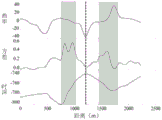
本实施例中,已经获得了时深特征图、方差特征图以及曲率特征图。例如,图7为本申请一实施例提供的断褶系统的宽度确定的示意图,如图7所示,对应同一横坐标,纵坐标从下往上分别为时深、方差以及曲率,分别对应时深特征图、方差特征图以及曲率特征图。图7对应的时深数据、方差数据以及曲率数据如表1所示。根据图7的时深特征图中的时深特征曲线,确定目标地层中包括断褶系统的第一距离范围,具体为:横坐标从750米到1800米之间有一个波峰,确定有断褶系统,750米处对应褶皱左翼转折处的断层开始点,1800米处对应褶皱右翼断层的结束点。In this embodiment, the time-depth feature map, the variance feature map, and the curvature feature map have been obtained. For example, FIG. 7 is a schematic diagram of determining the width of a pleating system provided by an embodiment of the present application. As shown in FIG. 7 , corresponding to the same abscissa, and the ordinate from bottom to top are time depth, variance, and curvature, respectively, corresponding to time Deep feature maps, variance feature maps, and curvature feature maps. The time-depth data, variance data and curvature data corresponding to Fig. 7 are shown in Table 1. According to the time-depth characteristic curve in the time-depth characteristic map of Fig. 7, the first distance range including the fault-fold system in the target stratum is determined. Specifically, there is a wave peak between 750 meters and 1,800 meters on the abscissa, and it is determined that there is a fault-fold system. System, 750 m corresponds to the fault start point at the turning point of the left flank of the fold, and 1800 m corresponds to the end point of the fault on the right flank of the fold.
S607、根据方差特征图,从第一距离范围内确定方差变化差异大于预设变化差异的第二距离范围。S607. According to the variance feature map, determine a second distance range in which the variance change difference is greater than the preset change difference from the first distance range.
本实施例中,已经确定了第一距离范围,再根据方差特征图,从第一距离范围内确定方差变化差异大于预设变化差异的第二距离范围。例如:如图7所示,已经确定了第一距离范围为:从横坐标750米到横坐标1800米,根据图7的方差特征图中的方差特征曲线,从第一距离范围内确定方差变化差异大于预设变化差异的第二距离范围。具体地,预设变化差异例如为0.3。在第一距离范围内,根据方差特征图中方差变化差异大于预设变化差异0.3,确定从横坐标750米到横坐标1100米处对应褶皱左翼转折处的断层范围;根据方差特征图,确定从横坐标1400米到横坐标1800米处对应褶皱右翼断层范围。据此,确定的第二距离范围包括:从横坐标750米到横坐标1100米,从横坐标1400米到横坐标1800米。In this embodiment, a first distance range has been determined, and then a second distance range in which the variance change difference is greater than the preset change difference is determined from the first distance range according to the variance feature map. For example, as shown in Figure 7, it has been determined that the first distance range is: from 750 meters on the abscissa to 1800 meters on the abscissa, and according to the variance characteristic curve in the variance characteristic map of Figure 7, the variance change is determined from the first distance range. The difference is greater than the second distance range of the preset variation difference. Specifically, the preset variation difference is, for example, 0.3. Within the first distance range, according to the variance change difference in the variance feature map being greater than the preset change difference of 0.3, determine the fault range from the abscissa 750 meters to the abscissa 1100 meters corresponding to the turning point of the left flank of the fold; The range from 1400m abscissa to 1800m abscissa corresponds to the fault range on the right flank of the fold. Accordingly, the determined second distance range includes: from 750 meters on the abscissa to 1100 meters on the abscissa, and from 1400 meters on the abscissa to 1800 meters on the abscissa.
S608、根据曲率特征图,从第二距离范围中确定存在曲率正负变化的第三距离范围。S608. According to the curvature feature map, determine a third distance range with positive and negative curvature changes from the second distance range.
本实施例中,已经确定了第二距离范围,再根据曲率特征图,从第二距离范围中确定存在曲率正负变化的第三距离范围。例如:如图7所示,根据图7的曲率特征图中的曲率特征曲线,从第二距离范围中确定存在曲率正负变化的第三距离范围,具体为:在横坐标750米到横坐标1100米的第二距离范围内,根据曲率特征图中曲率的正负交替变化,确定从横坐标750米到横坐标1100米处对应褶皱左翼转折处的断层范围为第三距离范围;在横坐标1400米到横坐标1800米的第二距离范围内,根据曲率特征图,确定从横坐标1400米到横坐标1800米处对应褶皱右翼转折处的断层范围为第三距离范围。据此,确定的第三距离范围包括:从横坐标750米到横坐标1100米处,从横坐标1400米到横坐标1800米。In this embodiment, the second distance range has been determined, and then a third distance range with positive and negative curvature changes is determined from the second distance range according to the curvature characteristic map. For example, as shown in FIG. 7, according to the curvature characteristic curve in the curvature characteristic map of FIG. 7, a third distance range with positive and negative curvature changes is determined from the second distance range, specifically: from the abscissa 750 meters to the abscissa Within the second distance range of 1100 meters, according to the alternating change of positive and negative curvature in the curvature characteristic map, it is determined that the fault range from the abscissa 750 meters to the abscissa 1100 meters corresponding to the turning point of the left flank of the fold is the third distance range; In the second distance range from 1400 meters to 1800 meters on the abscissa, according to the curvature characteristic map, the fault range from the 1400 meters on the abscissa to 1800 meters on the abscissa corresponding to the turning point of the right flank of the fold is determined as the third distance range. Accordingly, the determined third distance range includes: from 750 meters on the abscissa to 1100 meters on the abscissa, and from 1400 meters on the abscissa to 1800 meters on the abscissa.
S609、根据第三距离范围,确定断褶系统的宽度。S609, according to the third distance range, determine the width of the broken pleat system.
本实施例中,可以根据第三距离范围的距离长度,确定断褶系统的宽度,第三距离范围的距离长度可以由第三距离范围的起始点和结束点来确定。在一种可选的例子中,可以将第三距离范围内的距离长度,确定为断褶系统的宽度。In this embodiment, the width of the pleating system may be determined according to the distance length of the third distance range, and the distance length of the third distance range may be determined by the start point and the end point of the third distance range. In an optional example, the distance length within the third distance range may be determined as the width of the broken pleat system.
本实施例中,根据第三距离范围起始点和结束点的横坐标,两者之间的距离差,确定为断褶系统的宽度。如图7所示,具体为:在横坐标750米到横坐标1100米的第三距离范围内,根据两者横坐标的差值,确定对应褶皱左翼转折处的断层的宽度为350米,对应图7中左侧的灰色矩形阴影;在横坐标1400米到横坐标1800米的第二距离范围内,根据两者横坐标的差值,确定对应褶皱右翼转折处的断层的宽度为400米,对应图7中右侧的灰色矩形阴影。In this embodiment, according to the abscissa of the start point and the end point of the third distance range, and the distance difference between the two, the width of the broken pleat system is determined. As shown in Figure 7, it is specifically: within the third distance range from 750 meters abscissa to 1100 meters abscissa, according to the difference between the two abscissas, determine the width of the fault corresponding to the turning point of the left flank of the fold to be 350 meters, corresponding to The gray rectangle shade on the left side in Figure 7; in the second distance range from 1400 meters abscissa to 1800 meters abscissa, according to the difference between the two abscissas, the width of the fault at the turning point of the right flank of the fold is determined to be 400 meters, Corresponds to the gray rectangle shading on the right in Figure 7.
在上述实施例的基础上,可以获得图4中除C1测试线之外的其余4条测试线对应的时深特征图、方差特征图以及曲率特征图,进而确定该地层的断层在不同位置上的破碎宽度。On the basis of the above embodiment, the time-depth feature maps, variance feature maps, and curvature feature maps corresponding to the remaining four test lines except the C1 test line in FIG. broken width.
本申请提供的断褶系统的宽度确定方法,通过确定目标地层中的测试线,获取测试线上多个测试点的时深数据、方差数据和曲率数据,根据多个测试点的时深数据,获得时深特征图,时深特征图用于表示测试线中距离参考测试点不同距离处的时深,根据多个测试点的方差数据,获得方差特征图,方差特征图用于表示测试线中距离参考测试点不同距离处的方差,根据多个测试点的曲率数据,获得曲率特征图,曲率特征图用于表示测试线中距离参考测试点不同距离处的曲率,根据时深特征图,确定目标地层中包括断褶系统的第一距离范围,根据方差特征图,从第一距离范围内确定方差变化差异大于预设变化差异的第二距离范围,根据曲率特征图,从第二距离范围中确定存在曲率正负变化的第三距离范围,根据第三距离范围,确定断褶系统的宽度。因此,通过上述时深特征图、方差特征图以及曲率特征图的展示,能够快速、直观且直接地确认地层中断褶系统的宽度,有助于分析和判断构造型油气储层的油气的运移和储存状况,对油气开采具有指导意义。In the method for determining the width of a broken fold system provided by the present application, by determining the test line in the target formation, the time-depth data, variance data and curvature data of multiple test points on the test line are obtained, and according to the time-depth data of the multiple test points, Obtain the time-depth feature map, which is used to represent the time-depth at different distances from the reference test point in the test line. According to the variance data of multiple test points, the variance feature map is obtained, and the variance feature map is used to represent the test line. The variance at different distances from the reference test point, according to the curvature data of multiple test points, the curvature characteristic map is obtained. The curvature characteristic map is used to represent the curvature of the test line at different distances from the reference test point. According to the time-depth characteristic map, determine The target stratum includes a first distance range of the fault-fold system, and according to the variance feature map, a second distance range in which the variance change difference is greater than the preset change difference is determined from the first distance range, and according to the curvature feature map, from the second distance range A third distance range with positive and negative curvature changes is determined, and according to the third distance range, the width of the broken pleat system is determined. Therefore, through the display of the above time-depth feature map, variance feature map and curvature feature map, the width of the formation fault-fold system can be quickly, intuitively and directly confirmed, which is helpful for analyzing and judging the migration of oil and gas in structural oil and gas reservoirs and storage conditions, which have guiding significance for oil and gas exploitation.
图8为本申请一实施例提供的断褶系统的宽度确定装置的结构示意图,如图8所示,本实施例的断褶系统的宽度确定装置800包括:确定模块801、获取模块802、处理模块803。FIG. 8 is a schematic structural diagram of a device for determining the width of a pleating system provided by an embodiment of the present application. As shown in FIG. 8 , the device for determining the width of a
确定模块801,用于确定目标地层中的测试线。A
获取模块802,用于获取测试线上多个测试点的时深数据、方差数据和曲率数据。The acquiring
处理模块803,用于根据多个测试点的时深数据、方差数据和曲率数据,确定目标地层中断褶系统的宽度。The
在上述任一所示实施例的基础上,处理模块803具体用于:On the basis of any of the above-mentioned embodiments, the
根据多个测试点的时深数据,获得时深特征图,时深特征图用于表示测试线中距离参考测试点不同距离处的时深;根据多个测试点的方差数据,获得方差特征图,方差特征图用于表示测试线中距离参考测试点不同距离处的方差;根据多个测试点的曲率数据,获得曲率特征图,曲率特征图用于表示测试线中距离参考测试点不同距离处的曲率;根据时深特征图、方差特征图以及曲率特征图,确定目标地层中断褶系统的宽度。According to the time-depth data of multiple test points, the time-depth feature map is obtained, and the time-depth feature map is used to represent the time-depth at different distances from the reference test point in the test line; according to the variance data of multiple test points, the variance feature map is obtained , the variance feature map is used to represent the variance at different distances from the reference test point in the test line; according to the curvature data of multiple test points, the curvature feature map is obtained, and the curvature feature map is used to represent the test line at different distances from the reference test point. According to the time-depth feature map, variance feature map and curvature feature map, determine the width of the target formation discontinuity fold system.
在上述任一所示实施例的基础上,处理模块803具体用于:On the basis of any of the above-mentioned embodiments, the
根据时深特征图,确定目标地层中包括断褶系统的第一距离范围;根据方差特征图以及曲率特征图,从第一距离范围内确定断褶系统的宽度。According to the time-depth feature map, the first distance range including the fault-fold system in the target formation is determined; according to the variance feature map and the curvature feature map, the width of the fault-fold system is determined from the first distance range.
在上述任一所示实施例的基础上,处理模块803具体用于:On the basis of any of the above-mentioned embodiments, the
根据方差特征图,从第一距离范围内确定方差变化差异大于预设变化差异的第二距离范围;根据曲率特征图,从第二距离范围中确定存在曲率正负变化的第三距离范围;根据第三距离范围,确定断褶系统的宽度。According to the variance feature map, determine a second distance range in which the variance change difference is greater than the preset change difference from the first distance range; according to the curvature feature map, determine a third distance range with positive and negative curvature changes from the second distance range; The third distance range determines the width of the broken pleat system.
在上述任一所示实施例的基础上,处理模块803具体用于:On the basis of any of the above-mentioned embodiments, the
将第三距离范围内的距离长度,确定为断褶系统的宽度。The distance length within the third distance range is determined as the width of the broken pleat system.
在上述任一所示实施例的基础上,多个测试点分别为测试线上的等间距的测试点。On the basis of any of the above-mentioned embodiments, the plurality of test points are respectively equally spaced test points on the test line.
在上述任一所示实施例的基础上,测试线的方向与目标地层中断褶系统的走向垂直。On the basis of any of the above-described embodiments, the direction of the test line is perpendicular to the strike of the interrupted fold system of the target formation.
本实施例的装置,可以用于执行上述任一所示方法实施例的技术方案,其实现原理和技术效果类似,此处不再赘述。The apparatus in this embodiment can be used to implement the technical solutions of any of the above-described method embodiments, and the implementation principles and technical effects thereof are similar, and are not repeated here.
图9为本申请另一实施例提供的断褶系统的宽度确定装置的结构示意图,如图9所示,本实施例的断褶系统的宽度确定装置900包括:存储器901和处理器902。其中,存储器901、处理器902通过总线连接。9 is a schematic structural diagram of an apparatus for determining the width of a pleating system provided by another embodiment of the present application. As shown in FIG. 9 , the
存储器901用于存储程序指令。
处理器902用于调用存储器中的程序指令执行:The
确定目标地层中的测试线;获取测试线上多个测试点的时深数据、方差数据和曲率数据;根据多个测试点的时深数据、方差数据和曲率数据,确定目标地层中断褶系统的宽度。Determine the test line in the target stratum; obtain the time-depth data, variance data and curvature data of multiple test points on the test line; width.
在上述任一所示实施例的基础上,处理器902具体用于:On the basis of any of the above-mentioned embodiments, the
根据多个测试点的时深数据,获得时深特征图,时深特征图用于表示测试线中距离参考测试点不同距离处的时深;根据多个测试点的方差数据,获得方差特征图,方差特征图用于表示测试线中距离参考测试点不同距离处的方差;根据多个测试点的曲率数据,获得曲率特征图,曲率特征图用于表示测试线中距离参考测试点不同距离处的曲率;根据时深特征图、方差特征图以及曲率特征图,确定目标地层中断褶系统的宽度。According to the time-depth data of multiple test points, the time-depth feature map is obtained, and the time-depth feature map is used to represent the time-depth at different distances from the reference test point in the test line; according to the variance data of multiple test points, the variance feature map is obtained , the variance feature map is used to represent the variance at different distances from the reference test point in the test line; according to the curvature data of multiple test points, the curvature feature map is obtained, and the curvature feature map is used to represent the test line at different distances from the reference test point. According to the time-depth feature map, variance feature map and curvature feature map, determine the width of the target formation discontinuity fold system.
在上述任一所示实施例的基础上,处理器902具体用于:On the basis of any of the above-mentioned embodiments, the
根据时深特征图,确定目标地层中包括断褶系统的第一距离范围;根据方差特征图以及曲率特征图,从第一距离范围内确定断褶系统的宽度。According to the time-depth feature map, the first distance range including the fault-fold system in the target formation is determined; according to the variance feature map and the curvature feature map, the width of the fault-fold system is determined from the first distance range.
在上述任一所示实施例的基础上,处理器902具体用于:On the basis of any of the above-mentioned embodiments, the
根据方差特征图,从第一距离范围内确定方差变化差异大于预设变化差异的第二距离范围;根据曲率特征图,从第二距离范围中确定存在曲率正负变化的第三距离范围;根据第三距离范围,确定断褶系统的宽度。According to the variance feature map, determine a second distance range in which the variance change difference is greater than the preset change difference from the first distance range; according to the curvature feature map, determine a third distance range with positive and negative curvature changes from the second distance range; The third distance range determines the width of the broken pleat system.
在上述任一所示实施例的基础上,处理器902具体用于:On the basis of any of the above-mentioned embodiments, the
将第三距离范围内的距离长度,确定为断褶系统的宽度。The distance length within the third distance range is determined as the width of the broken pleat system.
在上述任一所示实施例的基础上,多个测试点分别为测试线上的等间距的测试点。On the basis of any of the above-mentioned embodiments, the plurality of test points are respectively equally spaced test points on the test line.
在上述任一所示实施例的基础上,测试线的方向与目标地层中断褶系统的走向垂直。On the basis of any of the above-described embodiments, the direction of the test line is perpendicular to the strike of the interrupted fold system of the target formation.
本实施例的装置,可以用于执行上述任一所示方法实施例的技术方案,其实现原理和技术效果类似,此处不再赘述。The apparatus in this embodiment can be used to implement the technical solutions of any of the above-described method embodiments, and the implementation principles and technical effects thereof are similar, and are not repeated here.
图10为本申请另一实施例提供的断褶系统的宽度确定装置的结构示意图,如图10所示,例如,断褶系统的宽度确定装置1000可以被提供为一服务器或计算机。参照图10,装置1000包括处理组件1001,其进一步包括一个或多个处理器,以及由存储器1002所代表的存储器资源,用于存储可由处理组件1001的执行的指令,例如应用程序。存储器1002中存储的应用程序可以包括一个或一个以上的每一个对应于一组指令的模块。此外,处理组件1001被配置为执行指令,以执行上述任一方法实施例。FIG. 10 is a schematic structural diagram of an apparatus for determining the width of a pleating system according to another embodiment of the present application. As shown in FIG. 10 , for example, the
装置1000还可以包括一个电源组件1003被配置为执行装置1000的电源管理,一个有线或无线网络接口1004被配置为将装置1000连接到网络,和一个输入输出(I/O)接口1005。装置1000可以操作基于存储在存储器1002的操作系统,例如Windows ServerTM,MacOS XTM,UnixTM,LinuxTM,FreeBSDTM或类似。The
本申请还提供一种计算机可读存储介质,计算机可读存储介质中存储有计算机执行指令,当处理器执行计算机执行指令时,实现如上断褶系统的宽度确定方法。The present application also provides a computer-readable storage medium, where computer-executable instructions are stored in the computer-readable storage medium, and when the processor executes the computer-executable instructions, the above method for determining the width of a pleating system is implemented.
上述的计算机可读存储介质,上述可读存储介质可以是由任何类型的易失性或非易失性存储设备或者它们的组合实现,如静态随机存取存储器(SRAM),电可擦除可编程只读存储器(EEPROM),可擦除可编程只读存储器(EPROM),可编程只读存储器(PROM),只读存储器(ROM),磁存储器,快闪存储器,磁盘或光盘。可读存储介质可以是通用或专用计算机能够存取的任何可用介质。The above-mentioned computer-readable storage medium, the above-mentioned readable storage medium can be realized by any type of volatile or non-volatile storage device or their combination, such as static random access memory (SRAM), electrically erasable Programmable Read Only Memory (EEPROM), Erasable Programmable Read Only Memory (EPROM), Programmable Read Only Memory (PROM), Read Only Memory (ROM), Magnetic Memory, Flash Memory, Magnetic or Optical Disk. A readable storage medium can be any available medium that can be accessed by a general purpose or special purpose computer.
一种示例性的可读存储介质耦合至处理器,从而使处理器能够从该可读存储介质读取信息,且可向该可读存储介质写入信息。当然,可读存储介质也可以是处理器的组成部分。处理器和可读存储介质可以位于专用集成电路(Application Specific IntegratedCircuits,简称:ASIC)中。当然,处理器和可读存储介质也可以作为分立组件存在于断褶系统的宽度确定装置中。An exemplary readable storage medium is coupled to the processor such that the processor can read information from, and write information to, the readable storage medium. Of course, the readable storage medium can also be an integral part of the processor. The processor and the readable storage medium may be located in application specific integrated circuits (Application Specific Integrated Circuits, ASIC for short). Of course, the processor and the readable storage medium may also be present as separate components in the width determination device of the break pleat system.
本领域普通技术人员可以理解:实现上述各方法实施例的全部或部分步骤可以通过程序指令相关的硬件来完成。前述的程序可以存储于一计算机可读取存储介质中。该程序在执行时,执行包括上述各方法实施例的步骤;而前述的存储介质包括:ROM、RAM、磁碟或者光盘等各种可以存储程序代码的介质。Those of ordinary skill in the art can understand that all or part of the steps of implementing the above method embodiments may be completed by program instructions related to hardware. The aforementioned program can be stored in a computer-readable storage medium. When the program is executed, the steps including the above method embodiments are executed; and the foregoing storage medium includes: ROM, RAM, magnetic disk or optical disk and other media that can store program codes.
最后应说明的是:以上各实施例仅用以说明本申请的技术方案,而非对其限制;尽管参照前述各实施例对本申请进行了详细的说明,本领域的普通技术人员应当理解:其依然可以对前述各实施例所记载的技术方案进行修改,或者对其中部分或者全部技术特征进行等同替换;而这些修改或者替换,并不使相应技术方案的本质脱离本申请各实施例技术方案的范围。Finally, it should be noted that the above embodiments are only used to illustrate the technical solutions of the present application, but not to limit them; although the present application has been described in detail with reference to the foregoing embodiments, those of ordinary skill in the art should understand that: The technical solutions described in the foregoing embodiments can still be modified, or some or all of the technical features thereof can be equivalently replaced; and these modifications or replacements do not make the essence of the corresponding technical solutions deviate from the technical solutions of the embodiments of the present application. scope.
Claims (8)
Priority Applications (1)
| Application Number | Priority Date | Filing Date | Title |
|---|---|---|---|
| CN202011023917.5A CN112198552B (en) | 2020-09-25 | 2020-09-25 | Method and device for determining width of pleating system |
Applications Claiming Priority (1)
| Application Number | Priority Date | Filing Date | Title |
|---|---|---|---|
| CN202011023917.5A CN112198552B (en) | 2020-09-25 | 2020-09-25 | Method and device for determining width of pleating system |
Publications (2)
| Publication Number | Publication Date |
|---|---|
| CN112198552A CN112198552A (en) | 2021-01-08 |
| CN112198552B true CN112198552B (en) | 2022-02-18 |
Family
ID=74008340
Family Applications (1)
| Application Number | Title | Priority Date | Filing Date |
|---|---|---|---|
| CN202011023917.5A Active CN112198552B (en) | 2020-09-25 | 2020-09-25 | Method and device for determining width of pleating system |
Country Status (1)
| Country | Link |
|---|---|
| CN (1) | CN112198552B (en) |
Families Citing this family (1)
| Publication number | Priority date | Publication date | Assignee | Title |
|---|---|---|---|---|
| CN113075747B (en) * | 2021-02-23 | 2024-01-30 | 中国石油天然气股份有限公司 | Reservoir fracture development area prediction method and device |
Citations (4)
| Publication number | Priority date | Publication date | Assignee | Title |
|---|---|---|---|---|
| CN106014369A (en) * | 2016-06-24 | 2016-10-12 | 中国石油天然气集团公司 | Acquisition method and device for oil and gas reservoir |
| US10295686B2 (en) * | 2016-06-06 | 2019-05-21 | Saudi Arabian Oil Company | Quantifying geologic growth history of subsurface oil field structures based on structural growth indications |
| CN111399049A (en) * | 2020-04-29 | 2020-07-10 | 西南石油大学 | A Fracture Strength Prediction Method Based on Data Volume Dimensionality Reduction and Discrete Coefficient Calculation |
| CN111948709A (en) * | 2020-07-30 | 2020-11-17 | 中国石油大学(北京) | A method, device and system for identifying fault zone structure |
Family Cites Families (1)
| Publication number | Priority date | Publication date | Assignee | Title |
|---|---|---|---|---|
| CN102736107B (en) * | 2011-04-07 | 2014-08-06 | 中国石油天然气股份有限公司 | Energy constraint heterogeneous reservoir thickness identification system |
-
2020
- 2020-09-25 CN CN202011023917.5A patent/CN112198552B/en active Active
Patent Citations (4)
| Publication number | Priority date | Publication date | Assignee | Title |
|---|---|---|---|---|
| US10295686B2 (en) * | 2016-06-06 | 2019-05-21 | Saudi Arabian Oil Company | Quantifying geologic growth history of subsurface oil field structures based on structural growth indications |
| CN106014369A (en) * | 2016-06-24 | 2016-10-12 | 中国石油天然气集团公司 | Acquisition method and device for oil and gas reservoir |
| CN111399049A (en) * | 2020-04-29 | 2020-07-10 | 西南石油大学 | A Fracture Strength Prediction Method Based on Data Volume Dimensionality Reduction and Discrete Coefficient Calculation |
| CN111948709A (en) * | 2020-07-30 | 2020-11-17 | 中国石油大学(北京) | A method, device and system for identifying fault zone structure |
Non-Patent Citations (1)
| Title |
|---|
| 基于地震属性对Anadarko盆地El-Reno地下走滑断裂带精细刻画;刘辉;《中国优秀硕士学位论文全文数据库 基础科学辑》;20200115(第01期);22-23、44、46-47、55-56 * |
Also Published As
| Publication number | Publication date |
|---|---|
| CN112198552A (en) | 2021-01-08 |
Similar Documents
| Publication | Publication Date | Title |
|---|---|---|
| Liu et al. | Hydraulic-fracture-width inversion using low-frequency distributed-acoustic-sensing strain data—Part I: Algorithm and sensitivity analysis | |
| US10983235B2 (en) | Characterizing depositional features by geologic-based seismic classification | |
| Wang | Uncertainty quantification and reduction in the characterization of subsurface stratigraphy using limited geotechnical investigation data | |
| EP3358376B1 (en) | Method and apparatus for unambiguously estimating seismic anisotropy parameters | |
| US11561312B2 (en) | Mapping near-surface heterogeneities in a subterranean formation | |
| WO2022256666A1 (en) | Method and system for reflection-based travel time inversion using segment dynamic image warping | |
| Zhou et al. | Data driven modeling and prediction for reservoir characterization using seismic attribute analyses and big data analytics | |
| CN105093300A (en) | A method and device for identifying the boundary of a geological body | |
| CN115524744A (en) | Roadway full-waveform inversion method based on cut-off frequency optimization and regularization constraints | |
| CN112198552B (en) | Method and device for determining width of pleating system | |
| CN104199088B (en) | Incident angle gather extraction method and system | |
| US9366773B2 (en) | Enhanced visualisation of geologic features in 3D seismic survey data | |
| US11531129B2 (en) | Picking seismic stacking velocity based on structures in a subterranean formation | |
| US8340912B2 (en) | Seismic attributes for structural analysis | |
| CN109100803B (en) | Method and device for determining micro-fracture | |
| Lv et al. | Integrated characterization of deep karsted carbonates in the Tahe Oilfield, Tarim Basin | |
| US10783693B2 (en) | Seismic image orientation using 3D integration operations | |
| US9052408B2 (en) | Method and system for detecting geometry variations of seismic reflections | |
| Li et al. | Heart Shape to Fracture Distance: Characterizing Hydraulic Fracture Propagation before Hits | |
| CN116933473A (en) | Gradient structure tensor coherent computing method based on Gaussian differential operator | |
| McKean et al. | Geomechanical and fracture network interpretation of a Devonian outcrop | |
| CN113050193B (en) | Method, device and system for identifying distribution of basement igneous rocks | |
| US12535606B2 (en) | Seismic inversion downscaling and extrapolation for generation of seismic images | |
| Chopra et al. | Evaluation of Geostatistical Techniques for Reservoir Characterization | |
| US12196903B2 (en) | Method and system for determining seismic velocities using global path tracing |
Legal Events
| Date | Code | Title | Description |
|---|---|---|---|
| PB01 | Publication | ||
| PB01 | Publication | ||
| SE01 | Entry into force of request for substantive examination | ||
| SE01 | Entry into force of request for substantive examination | ||
| GR01 | Patent grant | ||
| GR01 | Patent grant |