CN112197788A - Vehicle traveling state detection method and device - Google Patents
Vehicle traveling state detection method and device Download PDFInfo
- Publication number
- CN112197788A CN112197788A CN202011413417.2A CN202011413417A CN112197788A CN 112197788 A CN112197788 A CN 112197788A CN 202011413417 A CN202011413417 A CN 202011413417A CN 112197788 A CN112197788 A CN 112197788A
- Authority
- CN
- China
- Prior art keywords
- vehicle
- signal receiving
- signal
- units
- real
- Prior art date
- Legal status (The legal status is an assumption and is not a legal conclusion. Google has not performed a legal analysis and makes no representation as to the accuracy of the status listed.)
- Granted
Links
Images


Classifications
-
- G—PHYSICS
- G01—MEASURING; TESTING
- G01C—MEASURING DISTANCES, LEVELS OR BEARINGS; SURVEYING; NAVIGATION; GYROSCOPIC INSTRUMENTS; PHOTOGRAMMETRY OR VIDEOGRAMMETRY
- G01C23/00—Combined instruments indicating more than one navigational value, e.g. for aircraft; Combined measuring devices for measuring two or more variables of movement, e.g. distance, speed or acceleration
-
- G—PHYSICS
- G06—COMPUTING; CALCULATING OR COUNTING
- G06F—ELECTRIC DIGITAL DATA PROCESSING
- G06F17/00—Digital computing or data processing equipment or methods, specially adapted for specific functions
- G06F17/10—Complex mathematical operations
Abstract
The invention provides a vehicle running state detection method and a vehicle running state detection device, wherein the vehicle running state detection method comprises the steps of acquiring a signal of a signal detector in a preset detection area in the process that a vehicle passes through the preset detection area; the signal detector comprises a signal transmitting group and a signal receiving group which are respectively positioned at two sides of the advancing direction of the vehicle; according to the signal of the signal detector, the vehicle running state information is determined, the problem that the vehicle cannot be positioned or is not well positioned due to the fact that the sensor fails under the premise that only a single sensor is adopted and the number of the sensors is limited in the prior art is solved, and the real-time vehicle speed, the real-time running direction and the like can be determined while the vehicle position is accurately positioned.
Description
Technical Field
The invention relates to the technical field of measuring equipment, in particular to a method and a device for detecting a vehicle running state.
Background
The working mode of the automatic loading system is to automatically control the loading equipment to act according to the position and the speed of the vehicle, so that the material is automatically loaded into the vehicle. Therefore, the method is important for detecting the position and the speed of the vehicle, and accurate position and speed data are necessary conditions for automatic control process operation and are also key for avoiding safety accidents such as loading, unloading deviation, equipment collision with the vehicle and the like.
The existing vehicle positioning method is characterized in that a photoelectric sensor is often used for positioning a vehicle, is installed on the side surface of a loading channel and is fixed relative to a feeding port.
When a vehicle runs to the position of the sensor, the sensor gives a signal, and the position of the vehicle relative to the feeding port is the position of the photoelectric sensor and the feeding port. The photoelectric sensor is used as a fixed point trigger device, the detection precision meets the requirement, but the quantity is small, and the photoelectric sensor is easy to be interfered. For example, if a foreign object is blocked in front of the photoelectric sensor, the same effect can be caused, and the signal of the photoelectric sensor is an error signal at the moment, so that an accident is likely to be caused once the photoelectric sensor is used for loading control.
Disclosure of Invention
An object of the present invention is to provide a vehicle traveling state detection method capable of avoiding a positioning failure due to a failure of a sensor.
Another object of the present invention is to provide a vehicle traveling state detection device that executes the vehicle traveling state detection method.
In one aspect, an embodiment of the present invention provides a method for detecting a vehicle traveling state, including: the method comprises the steps that in the process that a vehicle passes through a preset detection area, signals of a signal detector in the preset detection area are obtained; the signal detector comprises a signal transmitting group and a signal receiving group which are respectively positioned at two sides of the advancing direction of the vehicle, the signal transmitting group comprises a plurality of signal transmitting units, and the signal receiving group comprises a plurality of signal receiving units which are in one-to-one correspondence with the signal transmitting units; the length of a detection area of the preset detection area is larger than the length of the body of any vehicle entering the preset detection area; the vehicle body length detection method comprises the steps that within any minimum vehicle body length range in a preset detection area, at least three signal transmitting units and three signal receiving units in one-to-one correspondence with the signal transmitting units are included, and the minimum vehicle body length is the vehicle body length corresponding to the vehicle with the shortest vehicle body length in any vehicle entering the preset detection area;
and determining vehicle running state information of the vehicle according to the signal of the signal detector, wherein the vehicle running state information comprises at least one of real-time vehicle position information, vehicle length information, real-time vehicle speed and real-time running direction of the vehicle relative to the preset detection area.
Further, the determining the vehicle traveling state information of the vehicle according to the information of the signal detector includes:
determining the number of first signal receiving units which are continuous in position and do not receive signals in the signal receiving group;
determining the number of second signal receiving units which are adjacent to the first signal receiving unit in the advancing direction of the vehicle, have continuous positions and receive signals;
determining the number of third signal receiving units which are adjacent to the first signal receiving unit and are positioned continuously in the direction deviating from the advancing direction of the vehicle and receive signals;
and if the number of the first signal receiving units is greater than or equal to a first preset value, and the number of the second signal receiving units and the number of the third signal receiving units are both greater than or equal to a second preset value, determining the real-time vehicle position information and the vehicle length information according to the number of the first signal receiving units and the length of each signal receiving unit, wherein the real-time vehicle position information comprises real-time vehicle head position information and real-time vehicle tail position information.
Further, the vehicle traveling state information further includes a distance between two adjacent vehicles, and the determining the vehicle traveling state information of the vehicle according to the information of the signal detector includes:
determining the number of fourth signal receiving units which are continuous in position and receive signals in the signal receiving group;
determining the number of fifth signal receiving units which are adjacent to the fourth signal receiving unit in the advancing direction of the vehicle, have continuous positions and do not receive signals;
determining the number of sixth signal receiving units which are adjacent to the fourth signal receiving unit and are positioned continuously and do not receive signals in the direction deviating from the advancing direction of the vehicle;
and if the number of the fourth signal receiving units is greater than or equal to a third preset value, and the number of the fifth signal receiving units and the number of the sixth signal receiving units are both greater than or equal to a second preset value, determining the distance between the two adjacent vehicles according to the number of the fourth signal receiving units and the length of each signal receiving unit.
Further, before determining the traveling state information of the vehicle based on the information of the signal detector, the method further includes:
and determining a signal receiving unit with wrong signal reception in the signal receiving group, and correcting the signal receiving information of the signal receiving unit.
Further, the eliminating the signal receiving unit with the signal receiving error in the signal receiving group and correcting the signal receiving information of the signal receiving unit includes:
if the number of seventh signal receiving units which are continuous in position and do not receive signals in the signal receiving group is smaller than a fourth preset value, determining that the seventh signal receiving units receive signals wrongly, and marking the seventh signal receiving units as received signals;
and if the number of eighth signal receiving units which are positioned continuously and receive signals in the signal receiving group is less than or equal to a fifth preset value, and the number of ninth signal receiving units which are positioned continuously and do not receive signals in the advancing direction and the direction deviating from the advancing direction of the vehicle are respectively adjacent to the eighth signal receiving units, and the number of tenth signal receiving units are both greater than the fifth preset value, determining that the eighth signal receiving units receive signals wrongly, and marking the eighth signal receiving units as not receiving signals.
Further, the determining the vehicle traveling state information of the vehicle according to the signal of the signal detector includes:
sampling the real-time vehicle position information of the vehicle at equal time intervals, and determining real-time vehicle head position information and real-time vehicle tail position information corresponding to each sampling moment;
and determining the real-time vehicle speed according to the first real-time vehicle head position information and the first real-time vehicle tail position information corresponding to the current sampling moment, and the second real-time vehicle head position information and the second real-time vehicle tail position information corresponding to the previous sampling moment.
Further, the determining the vehicle traveling state information according to the signal of the signal detector includes:
determining a first correlation direction connecting line of a signal transmitting unit which is blocked for the first time at the current moment and a corresponding signal receiving unit, and a second correlation direction connecting line of the signal transmitting unit which is blocked for the first time at the previous moment and the corresponding signal receiving unit;
and determining the real-time driving direction of the vehicle according to the relative direction of the first correlation direction connecting line and the second correlation direction connecting line, wherein the real-time driving direction comprises reverse driving or forward driving.
Furthermore, the signal transmitting units and the signal receiving units are beacons, and a group of correlation beacons is formed by any signal transmitting unit and the signal receiving unit corresponding to any signal transmitting unit.
Furthermore, a plurality of signal transmitting units are arranged at equal intervals along the advancing direction of the vehicle; the signal receiving units are arranged at equal intervals along the advancing direction of the vehicle.
On the other hand, the embodiment of the invention also provides a vehicle running state detection device, which comprises a plurality of signal transmitting units, a plurality of signal receiving units and a controller, wherein the plurality of signal receiving units are in communication connection with the controller, the controller is used for executing the vehicle running state detection method, the signal transmitting units and the signal receiving units are arranged at equal heights in the vertical direction, a loading channel for vehicles to pass through is arranged between the signal transmitting units and the signal receiving units, the length of the loading channel is greater than the length of any vehicle body entering the loading channel, at least three signal transmitting units and three signal receiving units in one-to-one correspondence with the signal transmitting units are included in any minimum vehicle body length range in a preset detection area, the minimum vehicle body length is any vehicle entering the preset detection area, and the vehicle body length corresponding to the vehicle with the shortest vehicle body length.
Has the advantages that:
the vehicle running state detection method and the vehicle running state detection device provided by the invention have the advantages that in the process that the vehicle passes through the preset detection area, the signal transmitting units at the left end and the right end of the vehicle are blocked by the vehicle, the electric signal transmitted by the controller is blocked and can not be received by the corresponding signal receiving unit, the signal receiving unit sends a feedback signal with the blocked signal to the controller, thereby leading the controller to obtain the vehicle advancing state of the position, obtaining the vehicle advancing state of the vehicle through the positions of the signal receiving units which can not receive signals in the whole preset detection area, overcoming the problems that the vehicle can not be positioned or the positioning is poor due to the failure of the sensor under the premise that only a single sensor is adopted and the number of the sensors is limited in the prior art, the method can accurately position the vehicle, and can determine the real-time vehicle speed, the real-time driving direction and the like.
Drawings
In order to more clearly illustrate the embodiments of the present invention or the technical solutions in the prior art, the drawings used in the description of the embodiments or the prior art will be briefly described below, and it is obvious that the drawings in the following description are some embodiments of the present invention, and other drawings can be obtained by those skilled in the art without creative efforts.
Fig. 1 is a flowchart of a method for detecting a vehicle traveling state according to an embodiment of the present invention;
fig. 2 is a side view of a vehicle travel state detection apparatus according to an embodiment of the present invention;
fig. 3 is a plan view of a vehicle travel state detection apparatus according to an embodiment of the present invention.
Icon: 1-a vehicle; 2-a signal receiving unit; 3-a feeding port; 4-a signal transmitting unit; 5-a loading area; 6-a controller.
Detailed Description
The technical solutions of the present invention will be described clearly and completely with reference to the following embodiments, and it should be understood that the described embodiments are some, but not all, embodiments of the present invention. All other embodiments, which can be derived by a person skilled in the art from the embodiments given herein without making any creative effort, shall fall within the protection scope of the present invention.
Examples
Fig. 1 is a flowchart of a method for detecting a vehicle traveling state according to an embodiment of the present invention, fig. 2 is a side view of a device for detecting a vehicle traveling state according to an embodiment of the present invention, fig. 3 is a top view of the device for detecting a vehicle traveling state according to an embodiment of the present invention, and for convenience of description, fig. 2 and fig. 3 show a vehicle 1, a material inlet 3, and a material loading area 5 in addition to a signal transmitting unit 4 and a signal receiving unit 2.
As shown in fig. 1, 2 and 3, a method for detecting a vehicle traveling state includes the following steps:
s101, acquiring a signal of a signal detector in a preset detection area in the process that the vehicle 1 passes through the preset detection area; the signal detector comprises a signal transmitting group and a signal receiving group which are respectively positioned at two sides of the advancing direction of the vehicle 1, the signal transmitting group comprises a plurality of signal transmitting units 4, and the signal receiving group comprises a plurality of signal receiving units 2 which are in one-to-one correspondence with the signal transmitting units 4; the length of a detection area of the preset detection area is greater than the length of any vehicle body of the vehicle 1 entering the preset detection area; in any minimum vehicle body length range in the preset detection area, the vehicle body length detection device at least comprises three signal transmitting units 4 and three signal receiving units 2 which are in one-to-one correspondence with the signal transmitting units 4, wherein the minimum vehicle body length is the vehicle body length corresponding to the vehicle with the shortest vehicle body length in any vehicle entering the preset detection area;
and S102, determining vehicle traveling state information of the vehicle 1 according to the signal of the signal detector, wherein the vehicle traveling state information comprises at least one of real-time vehicle position information, vehicle length information, real-time vehicle speed and real-time traveling direction of the vehicle 1 relative to a preset detection area.
In order to solve the problem that a single photoelectric sensor fails to work and causes positioning failure, the scheme utilizes a plurality of signal transmitting units 4 and signal receiving units 2 which correspond to the signal transmitting units 4 one by one to detect the vehicle, obtains the traveling state information of the vehicle, and avoids detection errors caused by the failure of the single detecting unit through the signal receiving units 2 and the signal transmitting units 4 as much as possible, and the length of a detection area of a preset detection area is larger than the length of any vehicle body entering the preset detection area. Preferably, a vehicle body length range of a vehicle entering the preset detection region may be determined according to historical experience or big data technology, and the detection region length of the preset detection region may be determined based on the maximum value of the vehicle body length range, even if the detection region length is greater than the maximum value of the vehicle body length range. In addition, in the scheme, at least three signal receiving groups are included in any minimum vehicle body length range in the preset detection area, and the minimum vehicle body length is the vehicle body length corresponding to the vehicle with the shortest vehicle body length in any vehicle entering the preset detection area. Preferably, the minimum body length can also be determined based on historical experience or big data technology.
The vehicle 1 may be an automobile or each carriage of a train, preferably a transportation vehicle, for example, a vehicle for transporting industrial materials, wherein the industrial materials may be coal or gangue.
The signal transmitting group is used for transmitting signals, and the signal receiving group is used for receiving the signals transmitted by the signal transmitting group, wherein the signal transmitting units 4 correspond to the signal receiving units 2 one by one, and under the condition of no shielding, the signal receiving units 2 can receive the signals transmitted by the signal transmitting units 4 corresponding to the signal receiving units 2. Optionally, the signal transmitting unit 4 may be an ultrasonic signal transmitting unit 4, and accordingly, the signal receiving unit 2 may be an ultrasonic signal receiving unit 2, the signal transmitting unit 4 may also be an infrared signal transmitting unit 4, and accordingly, the signal receiving unit 2 may be an infrared signal receiving unit 2, and the signal transmitting unit 4 may also be a laser signal transmitting unit 4, and accordingly, the signal receiving unit 2 may be a laser signal receiving unit 2, and in addition, the signal transmitting unit 4 and the signal receiving unit 2 may also be correlation beacons, that is, one signal transmitting unit 4 and the signal receiving unit 2 corresponding to the signal transmitting unit may form a set of correlation beacons.
In this embodiment, after the vehicle 1 enters the preset detection area, first, the signal transmitting unit 4 near the head of the vehicle 1 is blocked by the vehicle 1 for the first time, and the electrical signal transmitted by the signal transmitting unit is blocked and cannot be received by the corresponding signal receiving unit 2. At this time, the signal receiving unit 2 sends the controller 6 a signal which is blocked and does not receive a feedback signal of the signal transmitted by the signal transmitting unit 4, so that the controller 6 knows that the head of the vehicle 1 reaches the position. When the vehicle 1 moves along the advancing direction, the subsequent signal transmitting units 4 along the advancing direction of the vehicle 1 are sequentially influenced by the vehicle obstruction, and the controller 6 obtains the moving information of the vehicle 1 in the preset detection area and the real-time vehicle position information of the vehicle 1 relative to the preset detection area through the feedback of the corresponding signal receiving unit 2.
As the vehicle 1 moves in the preset detection area, the controller 6 may determine information such as a head position, a tail position, vehicle length information, a real-time vehicle speed, and a real-time driving direction of the vehicle 1 according to the number of the blocked signal receiving units 2 and the length corresponding to the corresponding number of the signal receiving units 2. The controller 6 may further determine the vehicle head length and the car compartment length according to the inherent attributes of the vehicle and the vehicle length information, where the inherent attributes of the vehicle may be obtained by using a big data technology, for example, the inherent attributes of the vehicle may include a shortest vehicle length, a longest vehicle length, a shortest vehicle head length, a longest vehicle head length, a shortest distance between the vehicle head and the car, and a longest distance between the vehicle head and the car, and it is understood that the foregoing is only an example of the inherent attributes of the vehicle, the vehicle head information, and the car compartment information, and cannot limit the ranges thereof, and the attribute information meeting the actual needs and any attribute information that can be obtained by using the big data technology may be included in this embodiment. It is understood that the vehicle inherent property information may also include a vehicle compartment wall thickness range and the like if the vehicle compartment wall is not negligible.
Illustratively, the vehicle 1 is a carriage of a train for transporting industrial materials, the material inlet 3 is arranged at a fixed position in a preset detection area, and during the material feeding process, materials need to be loaded into the material loading area 5 of the vehicle 1 from the material inlet 3. Through confirming vehicle state information that advances such as the real-time vehicle position information, real-time vehicle speed and the real-time direction of traveling of vehicle 1 in predetermineeing the detection zone, can confirm that the accurate relative position of the regional 5 of year material and dog-house 3 on the vehicle 1 and information such as the input feed quantity in the unit interval to control dog-house 3 and throw material accurately, avoid appearing the material and put in the condition outside carrying the material region 5.
In an alternative embodiment, determining the vehicle traveling state information of the vehicle 1 based on the information of the signal detector includes:
determining the number of first signal receiving units which are continuous in position and do not receive signals in the signal receiving group;
determining the number of second signal receiving units which are adjacent to the first signal receiving unit, have continuous positions and receive signals in the advancing direction of the vehicle 1;
determining the number of third signal receiving units which are adjacent to the first signal receiving unit, have continuous positions and receive signals in the direction deviating from the advancing direction of the vehicle 1;
if the number of the first signal receiving units is greater than or equal to a first preset value, and the number of the second signal receiving units and the number of the third signal receiving units are both greater than or equal to a second preset value, real-time vehicle position information and vehicle length information are determined according to the number of the first signal receiving units and the length of each signal receiving unit 2, wherein the real-time vehicle position information comprises real-time vehicle head position information and real-time vehicle tail position information.
Preferably, before determining the vehicle length information, it is determined that the entire vehicle enters the preset detection area, since the vehicle may shield the signal transmitting unit 4, and the area between two adjacent vehicles may not shield the signal transmitting unit 4, the real-time vehicle position information and the vehicle length information may be preferably determined according to the number of the signal transmitting units 4 which are continuously shielded and the number of the signal transmitting units 4 which are adjacent to the continuously shielded signal transmitting units 4 and are continuously not shielded. The real-time vehicle head position information can be preferably determined by determining the signal transmitting unit 4 blocked by the vehicle head or the corresponding signal receiving unit 2, and the real-time vehicle tail position information can be preferably determined by determining the signal transmitting unit 4 blocked by the vehicle tail or the corresponding signal receiving unit 2.
The first preset value may be determined by using a big data algorithm, and may also be determined according to actual needs, and preferably, the first preset value may be the number of the signal receiving units 2 corresponding to the shortest vehicle length. The second preset value can be determined according to actual needs, and for example, the second preset value can be 3.
Illustratively, the length of the preset detection area is 16m, and the length of each signal transmitting unit 4 or signal receiving unit 2 is 0.5m, that is, 32 signal transmitting units 4 and 32 signal receiving units 2 corresponding to the signal transmitting units 4 one to one are included in the preset detection area, the first preset value is 12, and the second preset value is 3. At the present time, it is determined that the number of first signal receiving units is 14, the number of second signal receiving units is 4, and the number of third signal receiving units is 14. Since the number of first signal receiving units 14 is greater than the first preset value 12, and the number of second signal receiving units 4 and the number of third signal receiving units 14 are greater than the second preset value 3, it can be determined that the entire vehicle is within the preset detection area, and the length of the vehicle is 14 × 0.5m =7 m.
Preferably, the real-time vehicle position information and the vehicle length information may be determined according to the following formula, specifically, the sequence of all signal receiving units in the preset detection area is set as Wherein, in the step (A),
 is 0 or 1,0 indicates not occluded, 1 indicates occluded, the sequence is divided into
 Conversion to run
 Wherein, in the step (A),
 the value of (b) is a consecutive number of 0's or consecutive 1's.
 Is a sequence of
 The total number of sequences of consecutive 0 sequences and consecutive 1 sequences, i.e. runs
 The number of the elements in (1) is,
 as a run of
 To (1)
 The number of the elements is one,
 indicating a first within a predetermined detection zone
 And (4) vehicles.
If sequence Initial value of (2)
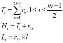
 If the current vehicle length is 1, T, H and L can be determined according to the following formulas, where T is real-time vehicle tail position information, H is real-time vehicle head position information, and L is vehicle length, and the specific formulas are as follows:


wherein the content of the first and second substances, is the actual length of one signal receiving unit,
 is the first in a preset detection zone
 The number of signal receiving units corresponding to the vehicle.
Illustratively, the sequence of all signal receiving units in the predetermined detection region is Wherein 1 represents a signal receiving unit which is shielded by the vehicle and does not receive the signal, 0 represents a signal receiving unit which receives the signal, and the signal receiving unit is converted into a run length
 ,
, Equal to 1, and is,
 equal to 5 in meters. Due to the sequence
 Initial value of (2)
 At 1, it may be considered that 4 represents a first vehicle (which may not have entered completely), 8 represents a second vehicle, and 6 represents a third vehicle (which may have partially exited from the preset detection zone). Of the corresponding first vehicle
 Equal to 1, and is,
 ,
, ,
, ,
, of a corresponding second vehicle
 Equal to 2, and is equal to 2,
 ,
, ,
, ,
, corresponding to
 ,
, ,
, 。
。
If sequence Initial value of (2)
 If 0, T, H and L can be determined according to the following formulas, where T is real-time vehicle tail position information, H is real-time vehicle head position information, and L is vehicle length, and the specific formulas are as follows:
wherein the content of the first and second substances, is the actual length of one signal receiving unit.
Illustratively, the sequence of all signal receiving units in the predetermined detection region is Wherein 1 represents a signal receiving unit which is shielded by the vehicle and does not receive the signal, 0 represents a signal receiving unit which receives the signal, and the signal receiving unit is converted into a run length
 ,
, Equal to 1 in meters. Due to the sequence
 Initial value of (2)
 If 0, the first 8 is considered to represent the first vehicle, and the second 8 represents the second vehicle, then the corresponding first vehicle
 ,
, ,
, Of a corresponding second vehicle
 ,
, ,
, 。
。
In an alternative embodiment, the vehicle traveling state information further includes a distance between two adjacent vehicles, and the vehicle traveling state information of the vehicle 1 is determined based on the information of the signal detector, including:
determining the number of fourth signal receiving units of the fourth signal receiving units which are continuous in position and receive signals in the signal receiving group;
determining the number of fifth signal receiving units which are adjacent to the fourth signal receiving unit in the advancing direction of the vehicle 1, have continuous positions and do not receive signals;
determining the number of sixth signal receiving units which are adjacent to the fourth signal receiving unit and are positioned continuously and do not receive signals in the direction deviating from the advancing direction of the vehicle 1;
if the number of the fourth signal receiving units is greater than or equal to the third preset value, and the number of the fifth signal receiving units and the number of the sixth signal receiving units are both greater than or equal to the second preset value, the distance between two adjacent vehicles is determined according to the number of the fourth signal receiving units and the length of each signal receiving unit 2.
Preferably, before the distance between two adjacent vehicles is determined, it is determined that two adjacent vehicles partially enter the preset detection area, since the vehicles may shield the signal transmitting unit 4, and the area between two adjacent vehicles may not shield the signal transmitting unit 4, and therefore, the distance between two adjacent vehicles may be preferably determined according to the number of consecutive non-shielded signal transmitting units 4 and the number of consecutive shielded signal transmitting units 4 adjacent to the consecutive non-shielded signal transmitting units 4.
The third preset value may be determined by using a big data algorithm, and may also be determined according to actual needs, and preferably, the third preset value may be the number of signal receiving units 2 corresponding to the shortest length between two adjacent vehicles. The second preset value can be determined according to actual needs, and for example, the second preset value can be 3.
Illustratively, the length of the preset detection area is 16m, and the length of each signal transmitting unit 4 or signal receiving unit 2 is 0.5m, that is, 32 signal transmitting units 4 and 32 signal receiving units 2 corresponding to the signal transmitting units 4 one to one are included in the preset detection area, the third preset value is 4, and the second preset value is 3. At the current moment, the number of the fourth signal receiving units is determined to be 4, and the number of the fifth signal receiving units and the number of the sixth signal receiving units are both 14. Since the fourth number of signal receiving units 4 is equal to the third preset value 4, and the fifth number of signal receiving units 14 and the sixth number of signal receiving units 14 are both greater than the second preset value 3, it can be determined that the area between two adjacent vehicles is completely in the preset detection area, and the distance between two adjacent vehicles is 4 × 0.5m =2 m.
In the actual detection, considering that the signal transmitting unit 4 or the signal receiving unit 2 may be damaged individually or blocked by foreign matter, that is, in the case where a vehicle passes through, the signal receiving unit 2 capable of receiving the signal transmitted by the signal transmitting unit 4 appears, and in the case where no vehicle passes through or an area between two adjacent vehicles passes through, the signal receiving unit 2 not receiving the signal transmitted by the signal transmitting unit 4 appears.
In view of the above, in an alternative embodiment, before determining the vehicle traveling state of the vehicle 1 based on the information of the signal detector, the method further includes:
the signal receiving unit 2 in which the signal reception in the signal receiving group is erroneous is determined, and the signal reception information of the signal receiving unit 2 is corrected.
Preferably, the converted run length can be used To determine the
 signal receiving unit 2 in the signal receiving group which has received the signal with error, is provided In order to preset the run value,
 for presetting the run-length value corresponding to the length of the vehicle, it is possible to use
 And
And determiningThe abnormal run length further specifies the
 signal receiving unit 2 in which the signal reception is erroneous. Illustratively, if the run is less than Then the signal receiving unit corresponding to the run can be considered as having an error, for example
 When run
 In existence of
 Then, it can be considered as
 The corresponding signal receiving unit has an error. If run is greater than
 Then the signal receiving unit corresponding to the run can be considered as having an error, for example
 When run
 In existence of
 Then, it can be considered as
 The corresponding signal receiving unit has an error.
Preferably, the signal receiving unit 2 with the wrong signal reception in the signal receiving group may be determined according to whether the number of the signal receiving units 2 which continuously receive the signal and the number of the signal receiving units 2 which continuously do not receive the signal satisfy the preset condition, and the signal receiving unit 2 with the wrong signal reception may be corrected.
In an alternative embodiment, excluding the signal receiving unit 2 with the signal receiving error in the signal receiving group, and modifying the signal receiving information of the signal receiving unit 2 includes:
if the number of the seventh signal receiving units which are continuous in position and do not receive signals in the signal receiving group is smaller than a fourth preset value, determining that the seventh signal receiving unit receives the signals wrongly, and marking the seventh signal receiving unit as a received signal;
if the number of eighth signal receiving units which are positioned continuously and receive signals in the signal receiving group is less than or equal to a fifth preset value, and the number of ninth signal receiving units which are positioned continuously and do not receive signals in the advancing direction and the direction deviating from the advancing direction of the vehicle 1 are respectively adjacent to the eighth signal receiving units, and the number of tenth signal receiving units are both greater than the fifth preset value, it is determined that the eighth signal receiving units receive signals incorrectly, and the eighth signal receiving units are marked as not receiving signals.
Optionally, the fourth preset value and the fifth preset value may be determined according to actual needs. Illustratively, the fourth preset value may be 4, and the fifth preset value may be 4.
For example, in the detection process, the feedback signal of the signal receiving unit 2 that has not received a signal is 1, the feedback signal of the signal receiving unit 2 that has received a signal is 0, and if the number of seventh signal receiving units of the seventh signal receiving unit that has continuous positions and the feedback signal of 1 is detected to be 3, and the number is smaller than the fourth preset value 4, it may be determined that the seventh signal receiving unit is a signal receiving unit that has an erroneous signal reception, and at this time, the feedback signal 1 of the seventh signal receiving unit may be changed to 0. If the number of the eighth signal receiving units of the eighth signal receiving unit, which detects that the positions are continuous and the feedback signal is 0, is 4, and the number of the ninth signal receiving units and the number of the tenth signal receiving units are both 5, because the number of the eighth signal receiving units 4 is equal to the fifth preset value 4, and both the number of the ninth signal receiving units 5 and the number of the tenth signal receiving units 5 are greater than the fifth preset value 4, it may be determined that the eighth signal receiving unit is a signal receiving unit with a wrong signal reception, and at this time, the feedback signal 0 of the eighth signal receiving unit may be changed to 1.
In an alternative embodiment, the vehicle traveling state information includes a real-time vehicle speed, and the vehicle traveling state information of the vehicle 1 is determined based on the signal of the signal detector, including:
sampling the real-time vehicle position information of the vehicle at equal time intervals, and determining the real-time vehicle head position information and the real-time vehicle tail position information corresponding to each sampling moment;
and determining the real-time vehicle speed according to the first real-time vehicle head position information and the first real-time vehicle tail position information corresponding to the current sampling moment, and the second real-time vehicle head position information and the second real-time vehicle tail position information corresponding to the previous sampling moment.
Preferably, the previous sampling instant is At the current sampling time of
 Is provided with
 The real-time position of the locomotive at any time is
 The real-time position of the tail of the vehicle is
 ,
, The real-time position of the locomotive at any time is
 The real-time position of the tail of the vehicle is
 Then the real-time vehicle speed may be determined according to the following equation:

in an alternative embodiment, the vehicle traveling state information includes a real-time traveling direction, and the vehicle traveling state information of the vehicle 1 is determined based on the signal of the signal detector, including:
determining a first correlation direction connecting line of the signal transmitting unit 4 which is blocked for the first time at the current moment and the corresponding signal receiving unit 2, and a second correlation direction connecting line of the signal transmitting unit 4 which is blocked for the first time at the previous moment and the corresponding signal receiving unit 2;
and determining the real-time driving direction of the vehicle 1 according to the relative direction of the first correlation direction connecting line and the second correlation direction connecting line. The real-time driving direction includes a reverse driving or a forward driving.
For example, if the direction of the first diagonal direction line with respect to the second diagonal direction line is a forward driving direction, the real-time driving direction of the vehicle may be considered as forward driving, and if the direction of the first diagonal direction line with respect to the second diagonal direction line is a reverse driving direction, the real-time driving direction of the vehicle may be considered as reverse driving.
For example, the real-time traveling direction may be determined according to the real-time vehicle speed, and if the real-time vehicle speed is positive, the real-time traveling direction of the vehicle may be considered as forward traveling, and if the real-time vehicle speed is negative, the real-time traveling direction of the vehicle may be considered as reverse traveling.
In an alternative embodiment, several signal emitting units 4 are arranged at equal intervals along the vehicle advancing direction; the plurality of signal receiving units 2 are arranged at equal intervals in the vehicle advancing direction.
In an alternative embodiment, any signal transmitting unit 4 sends a signal to the signal receiving unit 2 corresponding to any signal transmitting unit 4 in real time.
On the other hand, the device for detecting the vehicle position comprises a plurality of signal transmitting units 4, a plurality of signal receiving units 2 and a controller 6, wherein the plurality of signal receiving units 2 are in communication connection with the controller 6, the controller 6 is used for executing the vehicle running state detection method of any embodiment, the signal transmitting units 4 and the signal receiving units 2 are arranged in the same height along the vertical direction, a loading channel for the vehicle 1 to pass through is arranged between the signal transmitting units 4 and the signal receiving units 2, the length of the loading channel is larger than the length of the body of any vehicle 1 entering the loading channel, in any minimum vehicle body length range in the preset detection area, the vehicle body length detection device at least comprises three signal transmitting units 4 and three signal receiving units 2 in one-to-one correspondence with the signal transmitting units 4, wherein the minimum vehicle body length is the vehicle body length corresponding to the vehicle with the shortest vehicle body length in any vehicle entering the preset detection area.
The device that this embodiment provided can be at loading passageway both sides installation multiunit correlation formula measurement beacon, every group beacon head and the tail is adjacent to be a word arrangement, and the level keeps unanimous, constitutes the detection area of rectangular shape jointly.
The length of the measuring beacon combination exceeds the maximum length of the detected vehicle, the lengths of different vehicle models are different, the detection area covers the longest vehicle, the short vehicle can also realize detection, the position of the measuring beacon combination is fixed relative to the feeding port 3, the vehicle does not completely leave the area when the vehicle travels in the period from the beginning of loading to the end of loading, and if the current longest open wagon length is 13m, the length of the beacon combination is longer than 13 m. When the method is applied, 10 groups of single-group correlation measurement beacons with the length of 1.6m can be selected, and the length of a formed detection area is 16m, so that the coverage requirement is met. Other lengths and numbers of sets may be used as long as the same effect is achieved. The wheel base of the beacon is selected, each optical axis is a signal trigger point, the shorter the optical wheel base is, the higher the resolution and the higher the detection precision are, the short wheel base inevitably increases the number of the optical axes, and the signal processing efficiency is reduced due to the excessive number of the optical axes. Therefore, the proper wheelbase is selected according to the scene requirement, the precision requirement is met, and the detection efficiency is not influenced.
In the description of the embodiments of the present invention, unless otherwise explicitly specified or limited, the terms "mounted," "connected," and "connected" are to be construed broadly, e.g., as meaning either a fixed connection, a removable connection, or an integral connection; can be mechanically or electrically connected; they may be connected directly or indirectly through intervening media, or they may be interconnected between two elements. The specific meaning of the above terms in the present invention can be understood in specific cases for those skilled in the art.
In the description of the present invention, it should be noted that the terms "center", "upper", "lower", "left", "right", "vertical", "horizontal", "inner", "outer", etc., indicate orientations or positional relationships based on the orientations or positional relationships shown in the drawings, and are only for convenience of description and simplicity of description, but do not indicate or imply that the device or element being referred to must have a particular orientation, be constructed and operated in a particular orientation, and thus, should not be construed as limiting the present invention. Furthermore, the terms "first," "second," and "third" are used for descriptive purposes only and are not to be construed as indicating or implying relative importance.
Finally, it should be noted that: although the present invention has been described in detail with reference to the foregoing embodiments, those skilled in the art will understand that the following embodiments are merely illustrative of the present invention, and not restrictive, and the scope of the present invention is not limited thereto: any person skilled in the art can modify or easily conceive the technical solutions described in the foregoing embodiments or equivalent substitutes for some technical features within the technical scope of the present disclosure; such modifications, changes or substitutions do not depart from the spirit and scope of the embodiments of the present invention, and they should be construed as being included therein. Therefore, the protection scope of the present invention shall be subject to the protection scope of the claims.
Claims (10)
1. A vehicle travel state detection method characterized by comprising:
the method comprises the steps that in the process that a vehicle (1) passes through a preset detection area, signals of a signal detector in the preset detection area are obtained; the signal detector comprises a signal transmitting group and a signal receiving group which are respectively positioned at two sides of the advancing direction of the vehicle (1), the signal transmitting group comprises a plurality of signal transmitting units (4), and the signal receiving group comprises a plurality of signal receiving units (2) which are in one-to-one correspondence with the signal transmitting units (4); the length of a detection area of the preset detection area is larger than the length of the body of any vehicle (1) entering the preset detection area; in any minimum vehicle body length range in a preset detection area, the vehicle body length detection device at least comprises three signal transmitting units (4) and three signal receiving units (2) corresponding to the signal transmitting units (4) one by one, wherein the minimum vehicle body length is the vehicle body length corresponding to the vehicle (1) with the shortest vehicle body length in any vehicle (1) entering the preset detection area;
and determining vehicle running state information of the vehicle (1) according to the signal of the signal detector, wherein the vehicle running state information comprises at least one of real-time vehicle position information, vehicle length information, real-time vehicle speed and real-time running direction of the vehicle (1) relative to the preset detection area.
2. The method according to claim 1, wherein said determining vehicle travel state information of said vehicle (1) from information of said signal detector comprises:
determining the number of first signal receiving units which are continuous in position and do not receive signals in the signal receiving group;
determining the number of second signal receiving units which are adjacent to the first signal receiving unit, have continuous positions and receive signals in the advancing direction of the vehicle (1);
determining the number of third signal receiving units which are adjacent to the first signal receiving unit and are continuously positioned in the direction deviating from the advancing direction of the vehicle (1) and receive signals;
and if the number of the first signal receiving units is greater than or equal to a first preset value, and the number of the second signal receiving units and the number of the third signal receiving units are both greater than or equal to a second preset value, determining the real-time vehicle position information and the vehicle length information according to the number of the first signal receiving units and the length of each signal receiving unit (2), wherein the real-time vehicle position information comprises real-time head position information and real-time tail position information.
3. The method according to claim 1, wherein the vehicle travel state information further includes a distance between two adjacent vehicles, and the determining the vehicle travel state information of the vehicle (1) from the information of the signal detector includes:
determining the number of fourth signal receiving units which are continuous in position and receive signals in the signal receiving group;
determining the number of fifth signal receiving units which are adjacent to the fourth signal receiving unit and have continuous positions and do not receive signals in the advancing direction of the vehicle (1);
determining the number of sixth signal receiving units which are adjacent to the fourth signal receiving unit and are positioned continuously and do not receive signals in the direction deviating from the advancing direction of the vehicle (1);
and if the number of the fourth signal receiving units is greater than or equal to a third preset value, and the number of the fifth signal receiving units and the number of the sixth signal receiving units are both greater than or equal to a second preset value, determining the distance between the two adjacent vehicles according to the number of the fourth signal receiving units and the length of each signal receiving unit.
4. The method according to claim 2 or 3, characterized in that before determining the vehicle travel state information of the vehicle (1) from the information of the signal detector, it further comprises:
and determining a signal receiving unit (2) with a signal receiving error in the signal receiving group, and correcting the signal receiving information of the signal receiving unit (2).
5. The method of claim 4, wherein excluding the signal receiving unit (2) having a signal reception error in the signal receiving group and modifying the signal receiving information of the signal receiving unit (2) comprises:
if the number of seventh signal receiving units which are continuous in position and do not receive signals in the signal receiving group is smaller than a fourth preset value, determining that the seventh signal receiving units receive signals wrongly, and marking the seventh signal receiving units as received signals;
and if the number of eighth signal receiving units which are positioned continuously and receive signals in the signal receiving group is less than or equal to a fifth preset value, and the number of ninth signal receiving units which are positioned continuously and do not receive signals in the advancing direction and the direction deviating from the advancing direction of the vehicle (1) are respectively adjacent to the eighth signal receiving units, and the number of tenth signal receiving units are both greater than the fifth preset value, determining that the eighth signal receiving units receive signals wrongly, and marking the eighth signal receiving units as not receiving signals.
6. The method according to claim 2, wherein the vehicle travel state information comprises real-time vehicle speed, and the determining the vehicle travel state information of the vehicle (1) from the signal of the signal detector comprises:
sampling the real-time vehicle position information of the vehicle at equal time intervals, and determining real-time vehicle head position information and real-time vehicle tail position information corresponding to each sampling moment;
and determining the real-time vehicle speed according to the first real-time vehicle head position information and the first real-time vehicle tail position information corresponding to the current sampling moment, and the second real-time vehicle head position information and the second real-time vehicle tail position information corresponding to the previous sampling moment.
7. The method according to any one of claims 1-3, wherein the vehicle travel state information comprises a real-time driving direction, and the determining the vehicle travel state information of the vehicle (1) from the signal of the signal detector comprises:
determining a first correlation direction connecting line of a signal transmitting unit (4) which is blocked for the first time at the current moment and a corresponding signal receiving unit (2), and a second correlation direction connecting line of the signal transmitting unit (4) which is blocked for the first time at the previous moment and the corresponding signal receiving unit (2);
and determining the real-time driving direction of the vehicle (1) according to the relative direction of the first correlation direction connecting line and the second correlation direction connecting line, wherein the real-time driving direction comprises reverse driving or forward driving.
8. The method according to claim 1, wherein a plurality of said signal transmitting units (4) and a plurality of said signal receiving units (2) are beacons, and a set of correlation beacons is formed by any said signal transmitting unit (4) and the signal receiving unit (2) corresponding to any said signal transmitting unit (4).
9. Method according to claim 1, characterized in that a number of said signal emitting units (4) are arranged at equal intervals along the vehicle advancement direction; the signal receiving units (2) are arranged at equal intervals along the advancing direction of the vehicle.
10. A vehicle traveling state detection device, characterized by comprising a plurality of signal transmitting units (4), a plurality of signal receiving units (2) and a controller (6), wherein the plurality of signal receiving units (2) are in communication connection with the controller (6), the controller (6) is used for executing the vehicle traveling state detection method according to any one of claims 1 to 9, the signal transmitting units (4) and the signal receiving units (2) are arranged in a manner of equal height along the vertical direction, a loading channel for a vehicle to pass through is arranged between the signal transmitting units (4) and the signal receiving units (2), the length of the loading channel is larger than the length of the vehicle body of any vehicle (1) entering the loading channel, and at least three signal transmitting units (4) and three signal receiving units (2) corresponding to the signal transmitting units (4) one to one are included in any minimum vehicle body length range in a preset detection area ) And the minimum vehicle body length is the vehicle body length corresponding to the vehicle (1) with the shortest vehicle body length in any vehicle (1) entering the preset detection area.
Priority Applications (1)
| Application Number | Priority Date | Filing Date | Title |
|---|---|---|---|
| CN202011413417.2A CN112197788B (en) | 2020-12-07 | 2020-12-07 | Vehicle traveling state detection method and device |
Applications Claiming Priority (1)
| Application Number | Priority Date | Filing Date | Title |
|---|---|---|---|
| CN202011413417.2A CN112197788B (en) | 2020-12-07 | 2020-12-07 | Vehicle traveling state detection method and device |
Publications (2)
| Publication Number | Publication Date |
|---|---|
| CN112197788A true CN112197788A (en) | 2021-01-08 |
| CN112197788B CN112197788B (en) | 2021-03-12 |
Family
ID=74033835
Family Applications (1)
| Application Number | Title | Priority Date | Filing Date |
|---|---|---|---|
| CN202011413417.2A Active CN112197788B (en) | 2020-12-07 | 2020-12-07 | Vehicle traveling state detection method and device |
Country Status (1)
| Country | Link |
|---|---|
| CN (1) | CN112197788B (en) |
Citations (17)
| Publication number | Priority date | Publication date | Assignee | Title |
|---|---|---|---|---|
| CN201417141Y (en) * | 2009-07-06 | 2010-03-03 | 交通部公路科学研究院 | Outline, height difference and F/R suspension dynamic inspection system for automobiles and trains |
| CN102020121A (en) * | 2010-08-18 | 2011-04-20 | 东莞市罗尔机电科技有限公司 | System and method for automatic ration loading |
| CN102139804A (en) * | 2010-12-28 | 2011-08-03 | 三一重工股份有限公司 | Automatic charging system |
| CN102226696A (en) * | 2011-03-21 | 2011-10-26 | 王辉 | Measuring method of vehicle positioning ranging system for automatic coal sample acquisition system |
| JP2011252777A (en) * | 2010-06-02 | 2011-12-15 | Mk Seiko Co Ltd | Vehicle shape detector and car washing machine having the same |
| CN202784916U (en) * | 2012-09-27 | 2013-03-13 | 中国神华能源股份有限公司 | Locating vehicle extending arm position determination system and extending arm control system |
| CN103048697A (en) * | 2012-12-17 | 2013-04-17 | 华南理工大学 | Optical curtain device capable of measuring advancing direction, axial number and two-dimensional shape of vehicle |
| CN203037664U (en) * | 2013-05-02 | 2013-07-03 | 无锡职业技术学院 | Laser velocimeter |
| CN103234464A (en) * | 2013-04-22 | 2013-08-07 | 合肥市强科达科技开发有限公司 | Dynamic automatic measuring device for overall dimension of vehicle |
| CN103386993A (en) * | 2012-05-09 | 2013-11-13 | 深圳市坐标系交通技术有限公司 | System for acquiring running information of trains, optical transmitter and optical receiving and processing device |
| CN107807252A (en) * | 2017-10-25 | 2018-03-16 | 同方威视技术股份有限公司 | Vehicle Velocity Measurement Method and device |
| CN108106548A (en) * | 2018-02-01 | 2018-06-01 | 山西大学 | For the motor vehicle gabarit length measuring system of mobile testing line |
| CN207458339U (en) * | 2017-10-25 | 2018-06-05 | 西安建筑科技大学 | A kind of infrared light curtain vehicle sensor |
| CN108688692A (en) * | 2018-08-03 | 2018-10-23 | 北京华横新技术开发公司 | A kind of railroad train condition monitoring system and its detection method |
| CN109087516A (en) * | 2018-09-04 | 2018-12-25 | 四川大学 | A kind of road traffic detection system |
| CN109990876A (en) * | 2017-12-29 | 2019-07-09 | 锦州中理外轮理货有限公司 | A kind of automobile crosses the detection system, method and storage medium of weighing apparatus |
| CN111619619A (en) * | 2020-06-09 | 2020-09-04 | 中国华电科工集团有限公司 | Material trolley positioning start-stop method and system based on position compensation |
-
2020
- 2020-12-07 CN CN202011413417.2A patent/CN112197788B/en active Active
Patent Citations (17)
| Publication number | Priority date | Publication date | Assignee | Title |
|---|---|---|---|---|
| CN201417141Y (en) * | 2009-07-06 | 2010-03-03 | 交通部公路科学研究院 | Outline, height difference and F/R suspension dynamic inspection system for automobiles and trains |
| JP2011252777A (en) * | 2010-06-02 | 2011-12-15 | Mk Seiko Co Ltd | Vehicle shape detector and car washing machine having the same |
| CN102020121A (en) * | 2010-08-18 | 2011-04-20 | 东莞市罗尔机电科技有限公司 | System and method for automatic ration loading |
| CN102139804A (en) * | 2010-12-28 | 2011-08-03 | 三一重工股份有限公司 | Automatic charging system |
| CN102226696A (en) * | 2011-03-21 | 2011-10-26 | 王辉 | Measuring method of vehicle positioning ranging system for automatic coal sample acquisition system |
| CN103386993A (en) * | 2012-05-09 | 2013-11-13 | 深圳市坐标系交通技术有限公司 | System for acquiring running information of trains, optical transmitter and optical receiving and processing device |
| CN202784916U (en) * | 2012-09-27 | 2013-03-13 | 中国神华能源股份有限公司 | Locating vehicle extending arm position determination system and extending arm control system |
| CN103048697A (en) * | 2012-12-17 | 2013-04-17 | 华南理工大学 | Optical curtain device capable of measuring advancing direction, axial number and two-dimensional shape of vehicle |
| CN103234464A (en) * | 2013-04-22 | 2013-08-07 | 合肥市强科达科技开发有限公司 | Dynamic automatic measuring device for overall dimension of vehicle |
| CN203037664U (en) * | 2013-05-02 | 2013-07-03 | 无锡职业技术学院 | Laser velocimeter |
| CN107807252A (en) * | 2017-10-25 | 2018-03-16 | 同方威视技术股份有限公司 | Vehicle Velocity Measurement Method and device |
| CN207458339U (en) * | 2017-10-25 | 2018-06-05 | 西安建筑科技大学 | A kind of infrared light curtain vehicle sensor |
| CN109990876A (en) * | 2017-12-29 | 2019-07-09 | 锦州中理外轮理货有限公司 | A kind of automobile crosses the detection system, method and storage medium of weighing apparatus |
| CN108106548A (en) * | 2018-02-01 | 2018-06-01 | 山西大学 | For the motor vehicle gabarit length measuring system of mobile testing line |
| CN108688692A (en) * | 2018-08-03 | 2018-10-23 | 北京华横新技术开发公司 | A kind of railroad train condition monitoring system and its detection method |
| CN109087516A (en) * | 2018-09-04 | 2018-12-25 | 四川大学 | A kind of road traffic detection system |
| CN111619619A (en) * | 2020-06-09 | 2020-09-04 | 中国华电科工集团有限公司 | Material trolley positioning start-stop method and system based on position compensation |
Also Published As
| Publication number | Publication date |
|---|---|
| CN112197788B (en) | 2021-03-12 |
Similar Documents
| Publication | Publication Date | Title |
|---|---|---|
| US11262189B2 (en) | Monitoring container transfer device on lowering container onto transport platform or lifting away from transport platform | |
| CN111114593B (en) | Subway train autonomous positioning device, system and method based on multivariate information fusion | |
| KR101950543B1 (en) | Method and device for determining the installation position of a sensor module in a vehicle, and vehicle having such a device | |
| CN205427190U (en) | Moving target status monitoring device and vehicle quick check system thereof | |
| CN101162209B (en) | Equipment and method for quick-speed image-forming checking mobile target | |
| CN108674442B (en) | Train wheelbase detection method and system | |
| CN113276911B (en) | Method and system for detecting position of suspension type monorail vehicle section train | |
| RU2725332C1 (en) | System for decentralized interval control of train movements | |
| CN107921976B (en) | Detection device and method for monitoring a defined limit of a train of vehicles, in particular rail vehicles | |
| KR20120074530A (en) | Railway vehicle's running distance measuring system | |
| US6301532B1 (en) | Method for correction of a signal of at least one sensor on the basis of which a path curve can be determined, on which the vehicle is moving | |
| WO2019138532A1 (en) | Train control system and obstacle detection device | |
| CN112197788B (en) | Vehicle traveling state detection method and device | |
| CN111094104B (en) | Detecting and optimizing stop point accuracy for a vehicle | |
| US7987050B2 (en) | Material handling vehicle location system | |
| JP2020179708A (en) | Position estimation device, position estimation system and position estimation method | |
| WO2021075226A1 (en) | Sensor health confirmation system and railroad vehicle | |
| KR101981211B1 (en) | Precision-stopping measurement system | |
| CN105157670B (en) | Single track contact line leads high value measurement method | |
| CN110745112A (en) | Positioning detection system and battery replacing platform with same | |
| CN213812789U (en) | Deflection detector | |
| CN117490728B (en) | Lane line positioning fault diagnosis method and system | |
| CN217005724U (en) | Device and garage for acquiring automobile contour data | |
| KR101634148B1 (en) | Rail breakage detecting device and method thereof | |
| CN106515794A (en) | Continuous correction method for absolute position of train in local scope |
Legal Events
| Date | Code | Title | Description |
|---|---|---|---|
| PB01 | Publication | ||
| PB01 | Publication | ||
| SE01 | Entry into force of request for substantive examination | ||
| SE01 | Entry into force of request for substantive examination | ||
| GR01 | Patent grant | ||
| GR01 | Patent grant |