CN112170303A - Preparation system of processing is recycled to abandonment rubber component - Google Patents
Preparation system of processing is recycled to abandonment rubber component Download PDFInfo
- Publication number
- CN112170303A CN112170303A CN202011109459.7A CN202011109459A CN112170303A CN 112170303 A CN112170303 A CN 112170303A CN 202011109459 A CN202011109459 A CN 202011109459A CN 112170303 A CN112170303 A CN 112170303A
- Authority
- CN
- China
- Prior art keywords
- plate
- cleaning
- bearing
- frame
- face
- Prior art date
- Legal status (The legal status is an assumption and is not a legal conclusion. Google has not performed a legal analysis and makes no representation as to the accuracy of the status listed.)
- Withdrawn
Links
- 229920001971 elastomer Polymers 0.000 title claims abstract description 72
- 239000005060 rubber Substances 0.000 title claims abstract description 72
- 238000002360 preparation method Methods 0.000 title claims abstract description 5
- 238000004140 cleaning Methods 0.000 claims abstract description 108
- 230000007246 mechanism Effects 0.000 claims description 49
- 238000009736 wetting Methods 0.000 claims description 41
- 238000007790 scraping Methods 0.000 claims description 37
- 230000005540 biological transmission Effects 0.000 claims description 29
- XLYOFNOQVPJJNP-UHFFFAOYSA-N water Substances O XLYOFNOQVPJJNP-UHFFFAOYSA-N 0.000 claims description 8
- 230000010405 clearance mechanism Effects 0.000 claims description 5
- 230000008878 coupling Effects 0.000 claims 2
- 238000010168 coupling process Methods 0.000 claims 2
- 238000005859 coupling reaction Methods 0.000 claims 2
- 230000002146 bilateral effect Effects 0.000 claims 1
- 230000000694 effects Effects 0.000 abstract description 7
- 238000004064 recycling Methods 0.000 abstract description 6
- 239000002699 waste material Substances 0.000 abstract description 5
- 239000007788 liquid Substances 0.000 description 9
- 238000009434 installation Methods 0.000 description 3
- 238000007599 discharging Methods 0.000 description 2
- 230000004048 modification Effects 0.000 description 2
- 238000012986 modification Methods 0.000 description 2
- 238000005406 washing Methods 0.000 description 2
- 230000007547 defect Effects 0.000 description 1
- 239000012530 fluid Substances 0.000 description 1
- 238000005065 mining Methods 0.000 description 1
- 229920003052 natural elastomer Polymers 0.000 description 1
- 229920001194 natural rubber Polymers 0.000 description 1
- 239000002994 raw material Substances 0.000 description 1
- 238000010092 rubber production Methods 0.000 description 1
- 229920003051 synthetic elastomer Polymers 0.000 description 1
- 239000005061 synthetic rubber Substances 0.000 description 1
Images


Classifications
-
- B—PERFORMING OPERATIONS; TRANSPORTING
- B08—CLEANING
- B08B—CLEANING IN GENERAL; PREVENTION OF FOULING IN GENERAL
- B08B3/00—Cleaning by methods involving the use or presence of liquid or steam
- B08B3/04—Cleaning involving contact with liquid
- B08B3/041—Cleaning travelling work
-
- B08B1/12—
-
- B08B1/165—
-
- B08B1/20—
-
- B08B1/32—
-
- B—PERFORMING OPERATIONS; TRANSPORTING
- B08—CLEANING
- B08B—CLEANING IN GENERAL; PREVENTION OF FOULING IN GENERAL
- B08B13/00—Accessories or details of general applicability for machines or apparatus for cleaning
Abstract
The invention relates to a preparation and processing system for recycling waste rubber products, which comprises a bottom plate, a bearing device and a cleaning device, wherein the bearing device is arranged at the upper end of the bottom plate through a support column, the cleaning device is uniformly arranged in the middle of the bearing device, and the cleaning device is arranged on the bearing device. The rubber belt cleaning device can solve the problems that when the existing equipment recovers and cleans rubber belts, a plurality of rubber belts cannot be cleaned simultaneously, so that the rubber belt cleaning efficiency is reduced, and rubber belts with different sizes cannot be cleaned on one equipment, so that the applicability of the equipment is reduced, meanwhile, the surface of the rubber belt cannot be wetted, the phenomenon of incomplete cleaning of stains is easy to occur after cleaning is finished, the residual stains cannot be cleaned, so that the effect of cleaning the rubber belts is reduced, and the like.
Description
Technical Field
The invention relates to the technical field of rubber recycling, in particular to a preparation and processing system for recycling waste rubber products.
Background
The rubber product refers to various articles produced by taking natural or synthetic rubber as a raw material, and also includes rubber products produced by recycling waste rubber, the rubber industry is one of important basic industries of national economy, and the rubber product not only provides daily and medical light industrial rubber products which are indispensable to daily life for people, but also provides various rubber production equipment or rubber parts for heavy industries and emerging industries such as mining, traffic, building, machinery, electronics and the like.
At present, when the existing equipment is used for recovering and cleaning a rubber belt, the following defects generally exist: 1. the existing equipment can not clean a plurality of rubber belts simultaneously, so that the cleaning efficiency of the rubber belts is reduced, and can not clean the rubber belts with different sizes on one equipment, so that the applicability of the equipment is reduced; 2. the existing equipment can not wet the surface of the rubber belt, the phenomenon of incomplete cleaning of stains is easy to occur after the cleaning is finished, and the residual stains after scraping can not be cleaned, so that the cleaning effect of the rubber belt is reduced.
Disclosure of Invention
Technical problem to be solved
The invention can solve the problems that the prior equipment can not simultaneously clean a plurality of rubber belts when recovering and cleaning the rubber belts, thereby reducing the cleaning efficiency of the rubber belts, can not clean the rubber belts with different sizes on one equipment, thereby reducing the applicability of the equipment, can not wet the surfaces of the rubber belts, easily causes incomplete cleaning of stains after cleaning, can not clean residual stains, thereby reducing the cleaning effect of the rubber belts, and the like.
(II) technical scheme
In order to achieve the purpose, the invention adopts the following technical scheme that the waste rubber product recycling, preparing and processing system comprises a bottom plate, a bearing device and a cleaning device, wherein the bearing device is installed at the upper end of the bottom plate through a support column, the cleaning device is uniformly arranged in the middle of the bearing device, and the cleaning device is installed on the bearing device.
The bearing and placing device comprises a bearing and placing frame, an adjusting screw rod, bearing and placing rollers, a transmission rod, a transmission gear and a driving motor, wherein the bearing and placing frame is installed at the upper end of a base plate through a support column, a rectangular groove is formed in the upper end face of the bearing and placing frame, the bearing and placing frames are symmetrically arranged in the rectangular groove in the left-right direction, the bearing and placing frame positioned on the left side is installed on the lower end face of the rectangular groove, the bearing and placing frame positioned on the right side is connected with the side wall of the rectangular groove in a sliding fit mode, the outer end face of the bearing and placing frame positioned on the right side is connected with the adjusting screw rod through a bearing, the adjusting screw rod is connected with the bearing and placing frame in a thread fit mode, the upper end of the bearing and placing frame is evenly provided with an installation plate, the front end face of the installation plate is connected, the transfer line front end is connected with driving motor, driving motor installs on holding puts frame preceding terminal surface, concrete during operation, at first, lay a plurality of rubber belts on holding the roller through artificial mode, afterwards, manually rotate adjusting screw, adjusting screw drives the right side and holds and put the frame and remove, ensure that rubber belt is in the tensioning state, and can realize carrying out the function of tensioning to the rubber belt of unidimensional, thereby the rate of utilization of equipment has been improved, can clear up a plurality of rubber belts simultaneously, thereby the efficiency of rubber belt clearance has been improved, and finally, the manual start driving motor, driving motor drives drive gear through the transfer line and rotates, drive gear drives rubber belt through holding the roller and rotates.
The cleaning device comprises a cleaning plate, a lifting plate, an electric push rod, a linkage rod, a sliding plate, a wetting mechanism, a cleaning mechanism, a scraping block and a scraping mechanism, wherein the cleaning plate is arranged on the lower end face of a rectangular groove, the middle part of the cleaning plate is connected with the lifting plate in a sliding fit mode, the upper end face of the lifting plate is connected with the electric push rod, the electric push rod is arranged on the rear end face of the cleaning plate, the linkage rod is arranged on the left side of the electric push rod, the lower end of the linkage rod is arranged on the lifting plate, the sliding plate is arranged at the upper end of the linkage rod and is in sliding connection with the cleaning plate, the wetting mechanisms are symmetrically arranged above and below the sliding plate, the wetting mechanisms above the wetting mechanisms are arranged on the lower end face of the sliding plate, the wetting mechanisms below the lifting plate are arranged on the front end face of the cleaning plate, the cleaning, the clearance mechanism that is located the below is installed on the terminal surface before the clearance board, the clearance mechanism right side of top is provided with strikes off the piece, strike off a slope installation, it is provided with strikes off the mechanism to strike off a below, strike off the mechanism and install on the terminal surface before the clearance board, concrete during operation, let in wetting mechanism in with the washing liquid through artificial mode, afterwards, the manual work starts electric putter, electric putter moves the gangbar through the lifter plate and descends, the gangbar passes through the sliding plate and drives wetting mechanism and rubber belt contact, the washing liquid in the wetting mechanism is moist to the rubber belt, thereby be convenient for the spot on the rubber belt to get rid of, the incomplete phenomenon of clearance of avoiding appearing takes place, and simultaneously, strike off the piece and strike off the mechanism and strike off the spot after the wetting and strike off, clearance mechanism clears up the remaining spot after striking off, thereby the effect that the rubber.
The wetting mechanism comprises a cleaning frame, a wetting tube, a baffle, a connecting spring, a ball and a connecting hose, wherein the upper cleaning frame is arranged on the lower end face of the sliding plate, the lower cleaning frame is arranged on the front end face of the cleaning plate, a rectangular cavity is arranged in the cleaning frame, the side wall of the rectangular cavity is uniformly connected with the wetting tube in a sliding fit mode, the baffle is arranged at the outer end of the wetting tube, the connecting spring is uniformly connected between the inner end of the baffle and the side wall of the rectangular cavity, the ball is connected at the inner end of the wetting tube in a sliding fit mode, the connecting hose is arranged on the outer end face of the cleaning frame, the other end of the connecting hose is connected with the cleaning frame, when the cleaning mechanism works, cleaning liquid is continuously injected into the rectangular cavity in the cleaning frame in a manual mode, then the wetting tube is stressed to shrink, cleaning liquid flows to the surface of the rubber belt through the wetting tube, so as, the ball has the functions of drainage and transmission.
Preferably, clearance mechanism including clearance frame, rotor plate, auxiliary spring and arc, top clearance frame install under the lifter plate on the terminal surface, below clearance frame is installed before the clearance plate on the terminal surface, clearance frame is inside to have the rotor plate through round pin hub connection, be connected with auxiliary spring between rotor plate and the clearance frame, the arc is installed to rotor plate inner, the inner evenly is provided with the cleaning brush of arc, during concrete work, when rubber belt is rotatory, remaining spot is cleared up after the cleaning brush on the arc strikes off rubber belt.
Preferably, strike off the mechanism including striking off the frame, striking off board and supporting spring, strike off the frame and install on the terminal surface before the clearance board, strike off the frame inside and be connected with through sliding fit's mode and strike off the board, strike off the board and strike off and be connected with supporting spring between the frame, during specific work, strike off the board and strike off the processing to rubber belt surface.
Preferably, the gear teeth are uniformly arranged on one side, close to the mounting plate, of the outer surface of the bearing and placing roller and are connected with the transmission gear in a gear meshing mode, and the gear teeth are meshed with the transmission gear to play a role in transmission during specific work.
Preferably, the connecting hose is made of rubber and communicated with the rectangular cavity, and the connecting hose plays a role in connection during specific work.
Preferably, the side wall of the wetting tube is uniformly provided with water inlet holes near the baffle, the wetting tube is communicated with the rectangular cavity through the water inlet holes, and the water inlet holes are used for discharging cleaning liquid during specific work.
(III) advantageous effects
1. The bearing and placing device can be used for placing and cleaning a plurality of rubber belts at the same time, so that the rubber belt cleaning efficiency is improved, and the rubber belts with different sizes can be placed, so that the applicability of the equipment is improved;
2. the cleaning device adopted by the invention can be used for wetting the surface of the rubber belt, so that stains on the rubber belt can be conveniently removed, the phenomenon of incomplete cleaning is avoided, and the scraped residual stains can be cleaned, so that the cleaning effect is improved;
3. the cleaning device adopted by the invention can simultaneously scrape and clean the inner surface and the outer surface of the rubber belt, thereby improving the cleaning efficiency of the rubber belt.
Drawings
The invention is further illustrated with reference to the following figures and examples.
FIG. 1 is a schematic perspective view of the present invention;
FIG. 2 is a front view of the present invention;
FIG. 3 is a left side view of the present invention;
FIG. 4 is a cross-sectional view A-A of FIG. 3 in accordance with the present invention;
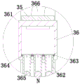
FIG. 5 is an enlarged view of the invention taken in the direction of N in FIG. 4;
fig. 6 is an enlarged view of the invention in the direction X of fig. 4.
Detailed Description
The embodiments of the invention will be described in detail below with reference to the drawings, but the invention can be implemented in many different ways as defined and covered by the claims.
As shown in fig. 1 to 6, in order to achieve the above object, the present invention adopts the following technical scheme that a system for recycling, preparing and processing waste rubber products comprises a bottom plate 1, a bearing device 2 and a cleaning device 3, wherein the bearing device 2 is installed at the upper end of the bottom plate 1 through a support column, the cleaning device 3 is evenly arranged in the middle of the bearing device 2, and the cleaning device 3 is installed on the bearing device 2.
The bearing device 2 comprises a bearing frame 21, a bearing frame 22, an adjusting screw 23, a bearing roller 24, a transmission rod 25, a transmission gear 26 and a driving motor 27, wherein the bearing frame 21 is installed at the upper end of the base plate 1 through a support column, a rectangular groove is formed in the upper end face of the bearing frame 21, the bearing frame 22 is symmetrically arranged in the rectangular groove in the left-right direction, the bearing frame 22 on the left side is installed on the lower end face of the rectangular groove, the bearing frame 22 on the right side is connected with the side wall of the rectangular groove in a sliding fit mode, the outer end face of the bearing frame 22 on the right side is connected with the adjusting screw 23 through a bearing, the adjusting screw 23 is connected with the bearing frame 21 in a threaded fit mode, mounting plates are uniformly arranged at the upper ends of the bearing frames 22, the front end face of the mounting plates is connected with the bearing roller 24 through a bearing, the transmission rod 25 is arranged below the bearing roller 24, the transmission rod 25 is evenly provided with transmission gears 26, the transmission gears 26 are in gear engagement with the carrying rollers 24, the front end of the transmission rod 25 is connected with a driving motor 27, the driving motor 27 is arranged on the front end surface of the carrying frame 21, when in specific work, a plurality of rubber belts are placed on the bearing roller 24 in a manual mode, then the adjusting screw 23 is rotated manually, the adjusting screw 23 drives the right bearing frame 22 to move, the rubber belts are ensured to be in a tensioning state, the function of tensioning the rubber belts with different sizes can be realized, thereby improving the utilization rate of the equipment, simultaneously cleaning a plurality of rubber belts, improving the cleaning efficiency of the rubber belts, and finally, the driving motor 27 is started manually, the driving motor 27 drives the transmission gear 26 to rotate through the transmission rod 25, and the transmission gear 26 drives the rubber belt to rotate through the carrying roller 24.
The outer surface of the supporting roller 24 is uniformly provided with gear teeth on one side close to the mounting plate, the gear teeth are connected with the transmission gear 26 in a gear meshing mode, and the gear teeth are meshed with the transmission gear 26 to play a transmission role during specific work.
The cleaning device 3 comprises a cleaning plate 31, a lifting plate 32, an electric push rod 33, a linkage rod 34, a sliding plate 35, a wetting mechanism 36, a cleaning mechanism 37, a scraping block 38 and a scraping mechanism 39, wherein the cleaning plate 31 is arranged on the lower end face of a rectangular groove, the middle part of the cleaning plate 31 is connected with the lifting plate 32 in a sliding fit mode, an extension plate is integrally formed at the rear end of the lifting plate 32, a through hole is formed in the side wall of the cleaning plate 31 corresponding to the extension plate and penetrates through the through hole to be led to the rear end of the cleaning plate 31, the upper end face of the lifting plate 32 is connected with the electric push rod 33, the electric push rod 33 is arranged on the rear end face of the cleaning plate 31, the linkage rod 34 is arranged on the left side of the electric push rod 33, the lower end of the linkage rod 34 is arranged on the lifting plate 32, the sliding plate 35 is arranged at the upper end of the linkage rod 34, the sliding plate 35 is in, the upper wetting mechanism 36 is arranged on the lower end face of the sliding plate 35, the lower wetting mechanism 36 is arranged on the front end face of the cleaning plate 31, the cleaning mechanisms 37 are symmetrically arranged on the upper and lower sides of the lifting plate 32, the upper cleaning mechanism 37 is arranged on the lower end face of the lifting plate 32, the lower cleaning mechanism 37 is arranged on the front end face of the cleaning plate 31, the right side of the upper cleaning mechanism 37 is provided with a scraping block 38, the scraping block 38 is obliquely arranged, the lower side of the scraping block 38 is provided with a scraping mechanism 39, the scraping mechanism 39 is arranged on the front end face of the cleaning plate 31, during specific work, cleaning liquid is introduced into the wetting mechanism 36 in a manual mode, then the electric push rod 33 is manually started, the electric push rod 33 drives the linkage rod 34 to descend through the lifting plate 32, the linkage rod 34 drives the wetting mechanism 36 to be contacted with the rubber belt through the sliding plate 35, and the cleaning liquid in the wetting mechanism 36 wet, therefore, stains on the rubber belt can be conveniently removed, the phenomenon of incomplete cleaning is avoided, meanwhile, the wetted stains are scraped by the scraping block 38 and the scraping mechanism 39, the residual stains after scraping are cleaned by the cleaning mechanism 37, and the effect of scraping the rubber belt is improved.
The wetting mechanism 36 comprises a cleaning frame 361, a wetting tube 362, a baffle 363, a connecting spring 364, balls 365 and a connecting hose 366, the upper cleaning frame 361 is arranged on the lower end face of the sliding plate 35, the lower cleaning frame 361 is arranged on the front end face of the cleaning plate 31, a rectangular cavity is arranged inside the cleaning frame 361, the wetting tube 362 is uniformly connected to the side wall of the rectangular cavity in a sliding fit manner, the baffle 363 is arranged at the outer end of the wetting tube 362, the connecting spring 364 is uniformly connected between the inner end of the baffle 363 and the side wall of the rectangular cavity, the balls 365 are connected to the inner end of the wetting tube 362 in a sliding fit manner, the connecting hose 366 is arranged on the outer end face of the cleaning frame 361, the other end of the connecting hose 366 is connected with the cleaning frame 361, during specific work, cleaning liquid is continuously injected into the rectangular cavity in the cleaning frame 361 in a manual manner, and then the wetting tube 362 is, the cleaning fluid flows to the surface of the rubber belt through the wetting pipe 362, so that the function of wetting the surface of the rubber belt is realized, and the balls have the functions of drainage and transmission.
The side wall of the wetting tube 362 is uniformly provided with water inlet holes near the baffle 363, the wetting tube 362 is communicated with the rectangular cavity through the water inlet holes, and the water inlet holes are used for discharging cleaning liquid during specific work.
The connecting hose 366 is made of rubber, the connecting hose 366 is communicated with the rectangular cavity, and the connecting hose 366 plays a connecting role during specific work.
The scraping mechanism 39 comprises a scraping frame 391, a scraping plate 392 and a supporting spring 393, wherein the scraping frame 391 is installed on the front end face of the cleaning plate 31, the scraping plate 392 is connected inside the scraping frame 391 in a sliding fit mode, the supporting spring 393 is connected between the scraping plate 392 and the scraping frame 391, and in specific work, the scraping plate 392 scrapes the surface of the rubber belt.
The above description is only a preferred embodiment of the present invention and is not intended to limit the present invention, and various modifications and changes may be made by those skilled in the art. Any modification, equivalent replacement, or improvement made within the spirit and principle of the present invention should be included in the protection scope of the present invention.
Claims (6)
1. The utility model provides a preparation system of processing is recycled to abandonment rubber component, includes bottom plate (1), holds puts device (2) and cleaning device (3), its characterized in that: the upper end of the bottom plate (1) is provided with a bearing device (2) through a support column, the middle part of the bearing device (2) is uniformly provided with a cleaning device (3), and the cleaning device (3) is arranged on the bearing device (2);
the bearing and placing device (2) comprises a bearing and placing frame (21), a bearing and placing frame (22), an adjusting screw rod (23), a bearing and placing roller (24), a transmission rod (25), a transmission gear (26) and a driving motor (27), wherein the bearing and placing frame (21) is installed at the upper end of a base plate (1) through a support column, a rectangular groove is formed in the upper end face of the bearing and placing frame (21), the bearing and placing frame (22) is arranged in the rectangular groove in a bilateral symmetry mode, the bearing and placing frame (22) positioned on the left side is installed on the lower end face of the rectangular groove, the bearing and placing frame (22) positioned on the right side is connected with the side wall of the rectangular groove in a sliding fit mode, the outer end face of the bearing and placing frame (22) on the right side is connected with the adjusting screw rod (23) through a bearing, the adjusting screw rod (23) is connected with the bearing and placing frame (21) in a thread fit, a transmission rod (25) is arranged below the bearing and placing roller (24) on the left side, the transmission rod (25) is connected with the mounting plate in a rotating fit mode, transmission gears (26) are uniformly mounted on the transmission rod (25), the transmission gears (26) are meshed with the bearing and placing roller (24) through gears, the front end of the transmission rod (25) is connected with a driving motor (27), and the driving motor (27) is mounted on the front end face of the bearing and placing frame (21);
the cleaning device (3) comprises a cleaning plate (31), a lifting plate (32), an electric push rod (33), a linkage rod (34), a sliding plate (35), a wetting mechanism (36), a cleaning mechanism (37), a scraping block (38) and a scraping mechanism (39), wherein the cleaning plate (31) is installed on the lower end face of a rectangular groove, the middle part of the cleaning plate (31) is connected with the lifting plate (32) in a sliding fit mode, the upper end face of the lifting plate (32) is connected with the electric push rod (33), the electric push rod (33) is installed on the rear end face of the cleaning plate (31), the linkage rod (34) is arranged on the left side of the electric push rod (33), the lower end of the linkage rod (34) is installed on the lifting plate (32), the sliding plate (35) is installed at the upper end of the linkage rod (34), the sliding plate (35) is in sliding connection with the cleaning plate (31), the wetting mechanism (36) is symmetrically arranged above, the upper wetting mechanism (36) is arranged on the lower end face of the sliding plate (35), the lower wetting mechanism (36) is arranged on the front end face of the cleaning plate (31), the cleaning mechanisms (37) are symmetrically arranged on the upper and lower sides of the lifting plate (32), the upper cleaning mechanism (37) is arranged on the lower end face of the lifting plate (32), the lower cleaning mechanism (37) is arranged on the front end face of the cleaning plate (31), the right side of the upper cleaning mechanism (37) is provided with a scraping block (38), the scraping block (38) is obliquely arranged, the scraping mechanism (39) is arranged below the scraping block (38), and the scraping mechanism (39) is arranged on the front end face of the cleaning plate (31);
the wetting mechanism (36) comprises a cleaning frame (361), a wetting pipe (362), a baffle plate (363), a connecting spring (364), a ball (365) and a connecting hose (366), upside clearance frame (361) install on sliding plate (35) terminal surface down, downside clearance frame (361) are installed on the terminal surface before clearance board (31), the inside rectangle cavity that is provided with of clearance frame (361), evenly be connected with moistening pipe (362) through sliding fit's mode on the rectangle cavity lateral wall, baffle (363) are installed to moistening pipe (362) outer end, evenly be connected with between baffle (363) inner and the rectangle cavity lateral wall connecting spring (364), moistening pipe (362) inner is connected with ball (365) through sliding fit's mode, coupling hose (366) are installed to the outer terminal surface of clearance frame (361), the coupling hose (366) other end is connected with clearance frame (361).
2. The system according to claim 1, wherein the system comprises: clearance mechanism (37) including clearance frame (371), rotor plate (372), auxiliary spring (373) and arc (374), top clearance frame (371) install on lifter plate (32) lower extreme face, below clearance frame (371) install on clearance board (31) preceding terminal surface, clearance frame (371) inside has rotor plate (372) through the round pin hub connection, be connected with auxiliary spring (373) between rotor plate (372) and clearance frame (371), arc (374) are installed to rotor plate (372) the inner, arc (374) evenly are provided with the clearance brush in arc (374).
3. The system according to claim 1, wherein the system comprises: scraping mechanism (39) including scraping frame (391), scraping board (392) and supporting spring (393), scraping frame (391) install on clearance board (31) front end face, scrape frame (391) inside and be connected with scraping board (392) through sliding fit's mode, be connected with supporting spring (393) between scraping board (392) and scraping frame (391).
4. The system according to claim 1, wherein the system comprises: gear teeth are uniformly arranged on one side, close to the mounting plate, of the outer surface of the bearing and placing roller (24), and the gear teeth are connected with the transmission gear (26) in a gear meshing mode.
5. The system according to claim 1, wherein the system comprises: the connecting hose (366) is made of rubber, and the connecting hose (366) is communicated with the rectangular cavity.
6. The system according to claim 1, wherein the system comprises: the side wall of the moistening pipe (362) is uniformly provided with water inlet holes close to the baffle plate (363), and the moistening pipe (362) is communicated with the rectangular cavity through the water inlet holes.
Priority Applications (1)
| Application Number | Priority Date | Filing Date | Title |
|---|---|---|---|
| CN202011109459.7A CN112170303A (en) | 2020-10-16 | 2020-10-16 | Preparation system of processing is recycled to abandonment rubber component |
Applications Claiming Priority (1)
| Application Number | Priority Date | Filing Date | Title |
|---|---|---|---|
| CN202011109459.7A CN112170303A (en) | 2020-10-16 | 2020-10-16 | Preparation system of processing is recycled to abandonment rubber component |
Publications (1)
| Publication Number | Publication Date |
|---|---|
| CN112170303A true CN112170303A (en) | 2021-01-05 |
Family
ID=73950647
Family Applications (1)
| Application Number | Title | Priority Date | Filing Date |
|---|---|---|---|
| CN202011109459.7A Withdrawn CN112170303A (en) | 2020-10-16 | 2020-10-16 | Preparation system of processing is recycled to abandonment rubber component |
Country Status (1)
| Country | Link |
|---|---|
| CN (1) | CN112170303A (en) |
Cited By (1)
| Publication number | Priority date | Publication date | Assignee | Title |
|---|---|---|---|---|
| CN113877857A (en) * | 2021-09-08 | 2022-01-04 | 黄俊斐 | Batch multi-directional dust remover for subway handles |
-
2020
- 2020-10-16 CN CN202011109459.7A patent/CN112170303A/en not_active Withdrawn
Cited By (2)
| Publication number | Priority date | Publication date | Assignee | Title |
|---|---|---|---|---|
| CN113877857A (en) * | 2021-09-08 | 2022-01-04 | 黄俊斐 | Batch multi-directional dust remover for subway handles |
| CN113877857B (en) * | 2021-09-08 | 2023-08-25 | 南京爱沃客信息科技有限公司 | Batch multidirectional dust remover for subway handles |
Similar Documents
| Publication | Publication Date | Title |
|---|---|---|
| CN209439162U (en) | A kind of liquid crystal display screen of mobile phone glass washing device | |
| CN109259712B (en) | Rolling pin surface dirt scrubbing equipment | |
| CN112170303A (en) | Preparation system of processing is recycled to abandonment rubber component | |
| CN214934040U (en) | Glass conveying device with automatic scrap cleaning function | |
| CN110586530A (en) | Tire inner wall washs cleans drying machine | |
| CN112295968A (en) | Recycling method of waste rubber products | |
| CN216881223U (en) | Automatic elbow flattening machine | |
| CN214526137U (en) | Leaked material recovery device of plate feeder | |
| CN113181690B (en) | Glass fiber wastewater treatment equipment | |
| CN214078347U (en) | Belt cleaning device for glass processing | |
| CN214398494U (en) | Belt conveyor convenient to overhaul | |
| CN212220677U (en) | Packaging hardware is used in instant noodle production with location structure | |
| CN212669571U (en) | Closestool bottom cleaning machine combined system | |
| CN209308654U (en) | A kind of automatic sand washing device | |
| CN207747572U (en) | A kind of print roller device for removing glaze | |
| CN109985853A (en) | A kind of cleaning device of mould steel processing | |
| CN220836812U (en) | Dust collector is used in polyurethane goods production | |
| CN220806669U (en) | Edge scraping device | |
| CN216231231U (en) | Printing machine environmental protection printing ink belt cleaning device | |
| CN220049348U (en) | Glass cleaning machine | |
| CN216323503U (en) | Silicon steel pretreatment strip steel surface cleanliness on-line detection system | |
| CN215236033U (en) | Full-automatic cleaning equipment for recycling waste metal | |
| CN219425187U (en) | Rinsing machine with detachable rinsing tank | |
| CN220479503U (en) | Automatic cleaning machine for rubber roller | |
| CN211538655U (en) | Glazing cleaning device for bathroom supplies |
Legal Events
| Date | Code | Title | Description |
|---|---|---|---|
| PB01 | Publication | ||
| PB01 | Publication | ||
| SE01 | Entry into force of request for substantive examination | ||
| SE01 | Entry into force of request for substantive examination | ||
| WW01 | Invention patent application withdrawn after publication |
Application publication date: 20210105 |
|
| WW01 | Invention patent application withdrawn after publication |