CN112166344A - Detection device - Google Patents
Detection device Download PDFInfo
- Publication number
- CN112166344A CN112166344A CN201980034007.6A CN201980034007A CN112166344A CN 112166344 A CN112166344 A CN 112166344A CN 201980034007 A CN201980034007 A CN 201980034007A CN 112166344 A CN112166344 A CN 112166344A
- Authority
- CN
- China
- Prior art keywords
- corner
- distance
- detection
- time variation
- detection device
- Prior art date
- Legal status (The legal status is an assumption and is not a legal conclusion. Google has not performed a legal analysis and makes no representation as to the accuracy of the status listed.)
- Granted
Links
Images


Classifications
-
- G—PHYSICS
- G01—MEASURING; TESTING
- G01S—RADIO DIRECTION-FINDING; RADIO NAVIGATION; DETERMINING DISTANCE OR VELOCITY BY USE OF RADIO WAVES; LOCATING OR PRESENCE-DETECTING BY USE OF THE REFLECTION OR RERADIATION OF RADIO WAVES; ANALOGOUS ARRANGEMENTS USING OTHER WAVES
- G01S13/00—Systems using the reflection or reradiation of radio waves, e.g. radar systems; Analogous systems using reflection or reradiation of waves whose nature or wavelength is irrelevant or unspecified
- G01S13/02—Systems using reflection of radio waves, e.g. primary radar systems; Analogous systems
- G01S13/06—Systems determining position data of a target
- G01S13/42—Simultaneous measurement of distance and other co-ordinates
-
- G—PHYSICS
- G01—MEASURING; TESTING
- G01S—RADIO DIRECTION-FINDING; RADIO NAVIGATION; DETERMINING DISTANCE OR VELOCITY BY USE OF RADIO WAVES; LOCATING OR PRESENCE-DETECTING BY USE OF THE REFLECTION OR RERADIATION OF RADIO WAVES; ANALOGOUS ARRANGEMENTS USING OTHER WAVES
- G01S13/00—Systems using the reflection or reradiation of radio waves, e.g. radar systems; Analogous systems using reflection or reradiation of waves whose nature or wavelength is irrelevant or unspecified
- G01S13/88—Radar or analogous systems specially adapted for specific applications
- G01S13/93—Radar or analogous systems specially adapted for specific applications for anti-collision purposes
- G01S13/931—Radar or analogous systems specially adapted for specific applications for anti-collision purposes of land vehicles
-
- G—PHYSICS
- G01—MEASURING; TESTING
- G01S—RADIO DIRECTION-FINDING; RADIO NAVIGATION; DETERMINING DISTANCE OR VELOCITY BY USE OF RADIO WAVES; LOCATING OR PRESENCE-DETECTING BY USE OF THE REFLECTION OR RERADIATION OF RADIO WAVES; ANALOGOUS ARRANGEMENTS USING OTHER WAVES
- G01S7/00—Details of systems according to groups G01S13/00, G01S15/00, G01S17/00
- G01S7/02—Details of systems according to groups G01S13/00, G01S15/00, G01S17/00 of systems according to group G01S13/00
-
- B—PERFORMING OPERATIONS; TRANSPORTING
- B60—VEHICLES IN GENERAL
- B60R—VEHICLES, VEHICLE FITTINGS, OR VEHICLE PARTS, NOT OTHERWISE PROVIDED FOR
- B60R99/00—Subject matter not provided for in other groups of this subclass
Landscapes
- Engineering & Computer Science (AREA)
- Radar, Positioning & Navigation (AREA)
- Remote Sensing (AREA)
- Physics & Mathematics (AREA)
- Computer Networks & Wireless Communication (AREA)
- General Physics & Mathematics (AREA)
- Electromagnetism (AREA)
- Radar Systems Or Details Thereof (AREA)
- Traffic Control Systems (AREA)
Abstract
The invention provides a detection device. In the detection apparatus (1), a transmitting antenna (TXANT1) transmits a modulated signal to space. The receiving antennas (RXANT1 to RXANT n) receive reflected waves of the modulated signal transmitted from the transmitting antenna (TXANT 1). The calculation unit is provided with distance peak detection units (31-3N) and an orientation detection unit (34), acquires the distance and orientation of the object at regular intervals from the reception signals of reflected waves received by the reception antennas (RANT 1-RANTN), and calculates the amount of change in distance over time from the acquired distance and orientation of the object. A corner detection unit (35) detects the corner of the object based on the amount of time change calculated by the calculation unit. The corner detection unit compares the time variation calculated by the calculation unit with a preset threshold value, detects a corner of the object when the time variation exceeds the threshold value, and outputs a corner detection signal.
Description
Technical Field
The present invention relates to a detection device, and more particularly to a technique effective for detecting a corner portion of an object by a radar system.
Background
As a technique for reducing the load on a driver driving a motor vehicle and reducing the accident rate, a driving assist system is receiving attention. One of the driving assistance systems is an automatic parking assistance system.
The automatic parking assist system is a system that detects a parking space, guides a vehicle into a separation line while keeping an appropriate distance from an adjacent vehicle at a target parking position, and automatically parks the vehicle.
In recent years, with the improvement in performance of millimeter wave radars, millimeter wave radars have been used not only for long-distance detection originally used but also for medium-distance and short-distance detection, and millimeter wave radars are used as detection devices for detecting corners and the like of a target vehicle at the time of automatic parking in order to realize automatic parking applications.
As a detection technique of a detection device using such a radar device, for example, in order to prevent erroneous grouping processing in which a reflection point group spanning a plurality of objects is determined as 1 object or the like when an object in front of the host vehicle is detected by a millimeter wave radar, it is known to calculate a right-end recognition point, a left-end recognition point, and a representative recognition point of the plurality of reflection points and perform grouping processing using estimated widths of the objects calculated based on respective amounts of change (see, for example, patent document 1).
Documents of the prior art
Patent document
Patent document 1: japanese patent laid-open publication No. 2015-132553
Disclosure of Invention
Problems to be solved by the invention
However, although the technique of patent document 1 judges whether or not the objects are the same object by the amount of time change in the recognition point, there is no description about the method of calculating the right-hand recognition point and the left-hand recognition point which are the corners of the objects.
In addition, when longitudinal parking or lateral parking is performed by automatic parking, it is necessary to extract the corner portion of the target vehicle quickly and correctly. In the case of patent document 1, as the right-end identification point, a reflection point located at the rightmost end in the left-right direction among the reflection points in the grouping range is used as the right-end identification point, but it is impossible to determine whether or not the corner of the object is present. In other words, the corner portion of the target vehicle cannot be detected, and there is a risk that the accuracy of automatic parking is reduced.
Further, as a technique of detecting a corner portion or the like in a target vehicle using the above-described millimeter wave radar, it is conceivable to detect a corner portion of a target vehicle by beam scanning with transmission beam forming of the millimeter wave radar.
However, in this case, a phase shifter or the like for performing transmission beamforming is newly required, and the number of transmission antennas increases. As a result, there is a problem that the cost of the detection device increases.
The invention aims to provide a technology capable of quickly and cheaply detecting the edge of an object in automatic parking application.
The above and other objects and novel features of the present invention will be described with reference to the accompanying drawings and description.
Means for solving the problems
The outline of a typical invention among the inventions disclosed in the present application will be briefly described as follows.
That is, the representative detection device has the 1 st transmitting antenna, a plurality of receiving antennas, a calculating section, and a corner detecting section. The 1 st transmitting antenna transmits a modulation signal to a space. The plurality of receiving antennas receive reflected waves of the modulated signal transmitted from the 1 st transmitting antenna.
The calculation unit acquires the distance and direction of the object at regular intervals from the reception signals of the reflected waves received by the plurality of reception antennas, and calculates the amount of time change in the distance from the acquired distance and direction of the object.
The corner detection unit detects a corner of the object based on the time variation calculated by the calculation unit. The corner detection unit compares the time variation calculated by the calculation unit with a preset threshold, detects a corner of the object when the time variation exceeds the threshold, and outputs a corner detection signal indicating that the corner of the object is detected.
In particular, the corner detection unit detects a point of the object corresponding to the distance and the orientation calculated by the calculation unit before the time when the time change amount exceeds the threshold value, as the corner of the object.
ADVANTAGEOUS EFFECTS OF INVENTION
Effects obtained by typical inventions among the inventions disclosed in the present application will be briefly described as follows.
A detection device with low cost and short detection time can be provided.
Drawings
Fig. 1 is an explanatory diagram showing an example of a configuration of a detection device according to embodiment 1.
Fig. 2 is an explanatory diagram for explaining an operation performed by the detection device of fig. 1.
Fig. 3 is a flowchart showing an example of operation processing performed by the detection device of fig. 1.
Fig. 4 is an explanatory diagram about a strong reflection signal of an object, signal intensity of a reflection point located between the strong reflection point and a corner of the object, and an orientation.
Fig. 5 is an explanatory diagram showing another example of the detection device of fig. 1.
Fig. 6 is a flowchart showing an example of detection processing performed by the detection device of fig. 5.
Fig. 7 is an explanatory diagram showing an example of a verification experiment for each scene of the vertical automatic parking, which is obtained by the study of the present inventors.
Fig. 8 is an explanatory diagram showing an example of the reception intensity in the millimeter wave radar having the wide-angle antenna for BSD application, which has been studied by the present inventors.
Fig. 9 is an explanatory diagram of an FFT spectrum in the verification experiment of fig. 8.
Fig. 10 is an explanatory diagram showing a relationship between the amount of spectral leakage power of the reflected signal and the intensity of the reflected signal.
Fig. 11 is an explanatory diagram showing an example of a configuration of the detection device according to embodiment 2.
Fig. 12 is an explanatory diagram of an operation performed by the detection device of fig. 11.
Fig. 13 is a flowchart showing an example of detection processing performed by the detection device of fig. 11.
Fig. 14 is a flowchart showing an example of detection processing when a new switch and a new transmitting antenna are provided in the detection apparatus of fig. 11.
Fig. 15 is an explanatory diagram showing an example of a configuration of the detection device according to embodiment 3.
Fig. 16 is an explanatory diagram of an operation in the detection device of fig. 15.
Fig. 17 is an explanatory diagram showing a relationship between the distance and the azimuth at each time of the distance positions R0 and R4 between the host vehicle and the target vehicle.
Fig. 18 is a flowchart showing an example of detection processing performed by the detection device of fig. 15.
Fig. 19 is a flowchart showing an example of detection processing when a new switch and a new transmitting antenna are provided in the detection device of fig. 15.
Fig. 20 is an explanatory diagram showing an example of the configuration of the detection device according to embodiment 4.
Fig. 21 is a flowchart showing an example of detection processing performed by the detection device of fig. 20.
Detailed Description
In all the drawings for explaining the embodiments, the same components are denoted by the same reference numerals in principle, and repeated explanation thereof will be omitted.
(embodiment mode 1)
The embodiments are described in detail below.
< example of Structure of detection device >
Fig. 1 is an explanatory diagram showing an example of a configuration of the detection device 1 according to embodiment 1.
As shown in fig. 1, the detection device 1 includes a transmitting/receiving antenna/analog section 2, a digital signal processing section 3, and a memory 4. The transmitting/receiving antenna/analog section 2 includes a frequency generator VCO, a transmitting antenna TXANT1, N receiving antennas RXANT1 to RXANT N constituting N receiving channels, N mixers MIX1 to MIX N, and N analog/digital converters ADC1 to ADCN. The receiving antennas RXANT1 to RXANT n are arranged at intervals at which a phase difference occurs in the received signal between the respective receiving channels in order to detect the azimuth of the object.
The modulation signal generated by the frequency generator VCO is distributed to the transmission antenna TXANT1 and the mixers MIX1 to MIX n, respectively. The modulated signal is, for example, a signal in the 79GHz band in the millimeter wave radar.
The 1 st transmitting antenna, i.e., the transmitting antenna TXANT1, transmits the modulated signal output from the frequency generator VCO to the space as an electromagnetic wave. The transmitted electromagnetic waves hit the object, and some of the reflected electromagnetic waves are received by the receiving antennas RXANT1 to RXANT n of the detection device 1.
The reception signals received by the reception antennas RXANT1 to RXANT n are converted into low-frequency signals by the mixers MIX1 to MIX, and are sent to the analog/digital converters ADC1 to ADCN.
The low-frequency signals converted by the mixers MIX1 to MIX n include frequency components corresponding to the distance between the detection apparatus 1 and the object. The low-frequency signals are converted into digital signals by the analog-to-digital converters ADC1 to ADCN, respectively, and then sent to the digital signal processing unit 3.
The digital signal processing unit 3 includes distance peak detection units 31 to 3N, an orientation detection unit 34, and a corner detection unit 35. The distance peak detection units 31 to 3N constituting the calculation unit convert the signals converted into digital signals by the analog/digital converters ADC1 to ADCN of the transmitting/receiving antenna/analog unit 2, for example, from time domain signals to frequency domain signals by FFT (Fast Fourier Transform) processing.
Then, the power intensity and phase information at the frequency proportional to the distance from the object to the detection device 1 are extracted from the converted frequency domain signal, and the extracted power intensity and phase information at the frequency are output to the azimuth detection unit 34.
The azimuth detection unit 34 constituting the calculation unit detects the azimuth in which the object is present by using signal processing of, for example, DBF (Digital Beam Forming) based on the power intensity and phase information at the frequency generated by the distance peak detection units 31 to 3N, and outputs information on the distance and azimuth of the object to the memory 4 and the corner detection unit 35, respectively.
The memory 4 stores information on the distance and the direction of the object output from the direction detecting unit 34 for each time t from t1 to t tN, and outputs the information on the distance and the direction of the object for each time to the corner detecting unit 35. Here, N at time t — tN is different from the number N of reception channels.
The corner detection unit 35 determines whether or not there is a corner of the object based on the information on the distance and the direction of the object output from the direction detection unit 34 and the information on the distance and the direction of the object for each time stored in the memory 4, and outputs a corner detection signal when the corner of the object is detected.
< principle of operation of the detection device 1 >
Here, the operation of the detection device 1 will be described.
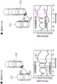
Fig. 7 is an explanatory diagram showing an example of a verification experiment for each scene of the vertical automatic parking, which is obtained by the study of the present inventors. Fig. 8 is an explanatory diagram showing an example of reception intensity in a millimeter wave radar having a wide-angle antenna for bsd (band Spot detection) application, which has been studied by the present inventors.
First, the inventors performed a verification experiment for each scene of the longitudinal automatic parking shown in fig. 7 in order to realize an automatic parking application using a millimeter wave radar.
Fig. 7 shows an example in which a wall 105 is provided on the left side, a curb 106 is provided on the right side, and the vehicle 101 and the vehicle 102 are parked longitudinally along the curb 106 with a parking space corresponding to 1 vehicle being separated, so that the vehicle 100 is automatically parked between the vehicle 101 and the vehicle 102.
In fig. 7, in a state where automatic parking is started, the host vehicle 100 needs to accurately and quickly recognize a rear corner of the vehicle 101, which is a target vehicle parked in front.
For example, in the case of observing the side portion of the target vehicle 101 with a millimeter wave radar having a wide-angle antenna, a signal of a distance position R0 at which electromagnetic waves emitted as shown by a solid line in fig. 8 are vertically incident with respect to the target vehicle 101 is strongly received. On the other hand, the signals at the distance positions R1 to R5, which are incident from an angle other than the perpendicular angle shown by the broken line in fig. 8, are specularly reflected, and the reception intensity is reduced.
In particular, the sharper the incident angle, the stronger the specular reflection, and the very small received power at the corner of the target vehicle 101 to be detected, i.e., at the distance position R5 shown in fig. 8, and it is difficult to detect the corner of the target vehicle 101 if the vehicle 100 is not moved backward and the corner approaches the distance position R0.
Fig. 9 is an explanatory diagram of an FFT spectrum in the verification experiment of fig. 8.
As shown in the FFT spectrum of fig. 9, the received signal from the distance position R0 having a strong reflection intensity also affects the received signals from the distance positions R1 to R5 due to spectrum leakage caused by the window function in the FFT processing, and makes the corner detection of the target vehicle 101 more difficult. Here, the distance intervals between the distance positions R0 to R1 and the distance positions R1 to R2, … … are determined by the resolution of the FFT.
As described above with reference to fig. 9, the received signal from the distance position R0 having a strong reflection intensity also affects the received signals from the distance positions R1 to R5 due to the spectrum leakage caused by the window function in the FFT processing.
However, the present inventors have conducted detailed studies and found that, in the distance between the distance position R0 where the reflection intensity is strong and the distance position where the corner of the target vehicle 101 is present, there is a signal at the distance position which is not masked by the spectral leakage power at the distance position R0 and which is larger than the noise floor.
Fig. 10 is an explanatory diagram showing a relationship between the amount of spectral leakage power of the reflected signal and the intensity of the reflected signal. This fig. 10 shows the result of comparison regarding the amount of spectral leakage power of the reflected signal from the distance position R0 in fig. 8 and the intensity of the reflected signal from the distance position R4.
The spectral leakage power at the distance position R0 decreased with distance from bin, and at the distance bin at the distance position R4, the spectral leakage power was about 10dB smaller than that at the distance position R0, and the azimuth detection was performed with DBF, and it was confirmed that the azimuth at the distance position R4 could be detected. The detection technique in the detection device 1 is based on this conclusion.
< example of operation of detection device 1 >
The operation of the detection device 1 will be described in detail below.
Fig. 2 is an explanatory diagram for explaining an operation performed by the detection device 1 of fig. 1. Fig. 3 is a flowchart showing an example of the operation process performed by the detection device 1 of fig. 1. The flowchart shown in fig. 3 shows a process mainly performed by the digital signal processing unit 3 of the detection device 1.
First, when time t shown in fig. 2 is t1, the automatic parking process by vehicle 100 is started. When the time t is t1, the detection device 1 transmits, in other words, radiates electromagnetic waves to the target vehicle 101, and the reception antennas RXANT1 to RXANT n of the detection device 1 receive reflected waves from the target vehicle 101.
The received reception signal is subjected to frequency conversion and converted into a digital signal by the transmitting/receiving antenna/analog section 2 of the detection device 1, and is output to the digital signal processing section 3. The digital signal is subjected to FFT processing by the distance peak detection units 31 to 3N of the digital signal processing unit 3, and a frequency proportional to the distance from the object to the detection device 1 and power intensity and phase information at the frequency are extracted. The power intensity and phase information at the frequency are output to the azimuth detecting section 34.
The direction detector 34 acquires information on the distance and direction between the distance position R0 where the reflection intensity is strong and the distance position R4 where the corner of the target vehicle 101 is present, by using DBF processing, based on the power intensity and phase information at the frequency generated by the distance peak detectors 31 to 3N (step S101). In the example shown in fig. 2, the angle ≈ R4 becomes 2 °.
The direction detector 34 outputs the information of the distance and the direction from the distance position R4 of the target vehicle 101 to the memory 4 and the corner detector 35, respectively. The memory 4 stores information of the distance and the direction when the time t of the distance position R4 of the target vehicle 101 output from the direction detection unit 34 equals t 1.
Similar signal processing is performed for the next time t-t 2, and information on the distance and direction from the distance position R4 of the target vehicle 101 at the time t-t 2 is output to the memory 4 and the corner detector 35. In the example shown in fig. 2, the information of the azimuth is the angle ═ R4 of 2 °.
The corner detector 35 compares the information on the distance and direction from the distance position R4 at time t1 with the information on the distance and direction from the distance position R4 at time t2, and determines whether or not the amount of change between the two values reaches a predetermined threshold value.
The threshold value is input from the outside, for example, an ecu (electronic Control unit) or the like that controls automatic driving in vehicle 100. Alternatively, the threshold value stored in the memory 4 in advance may be acquired.
If the fluctuation amount is smaller than the threshold value, the process returns to step S101 again (step S102). In the example of fig. 2, the amount of fluctuation of the angle &r 4 is equal to or less than the threshold value, and therefore the process returns to step S101 again. In addition, the time interval between the time t-t 1 and the time t-t 2 depends on the processing time for calculating the distance and the orientation, which is on the order of 10ms in the case of the millimeter wave radar.
The same signal processing is performed also at the time t equal to tN, and information on the distance and the direction of the distance position R4 of the target vehicle 101 at the time t equal to tN is output to the memory 4 and the corner detecting unit 35, respectively. In the example of fig. 2, the angle R4 is 45 °.
The corner detection unit 35 compares the information of the distance and the orientation at the distance position R4 at time t1, t2, and … … tN-1 with the information of the distance and the orientation at the distance position R4 at time t tN to determine whether or not the fluctuation amounts of both exceed a set threshold value, and if the fluctuation amount is greater than the threshold value, determines that a corner exists at the distance position (step S103). In the case of the example of fig. 2, when time t is tN, the amount of variation of the angle R4 is 43 ° and exceeds the threshold value.
More precisely, the distance and the azimuth from the position R4 at the time t — tN-1 indicate the corner position of the target vehicle 101. In addition, since the object existing in the 2 ° azimuth calculated as the azimuth of the distance position R4 at the time t1< t < tN changes from the corner of the target vehicle 101 to the wall 105, the distance position R4 in the 2 ° azimuth is converted into another distance position. In the case of fig. 2, when time t is tN, the distance position of the 2 ° azimuth changes from the distance position R4 to the distance position R14. Therefore, the threshold value of the fluctuation amount may be a fluctuation amount of the azimuth of a certain distance position of interest, a fluctuation amount of the distance in a certain azimuth of interest, or both.
Through the above processing, the detection device 1 can detect the corner of the rear portion of the target vehicle 101 quickly by performing determination based on the time variation of the distance position and the azimuth of the target vehicle 101.
In addition, since the corner of the rear portion of the target vehicle 101 can be detected with high accuracy without using a transmission beam forming technique or the like, the detection apparatus 1 can be provided at low cost.
< validity of the detecting device 1 >
Fig. 4 is an explanatory diagram about a strong reflection signal of an object, signal intensity of a reflection point located between the strong reflection point and a corner of the object, and an orientation.
Fig. 4 shows the results of an experiment performed to confirm validity in the detection apparatus 1 of fig. 1.
At the time corresponding to the time t-t 2 shown on the left side of fig. 4, the orientation of the distance R4 between the distance position R0 where the reflection intensity is strong and the distance position where the corner of the target vehicle 101 exists is calculated to be-15 °.
On the other hand, the distance to the corner of the target vehicle 101 shown on the right side of fig. 4 coincides with the distance position R4 at a time equivalent to time t — tN, and the azimuth of the distance position R4 is calculated to be +30 °.
That is, it can be confirmed that the direction of the distance position R4 has changed by 45 ° from time t to time t, t2, and the corner of the rear portion of the target vehicle 101 can be detected by the detection device 1.
The reason why the azimuth of the distance position R4 is 30 ° when the time t is tN is that the spectrum leakage from the distance position R0 having strong reflection intensity affects the distance position R4, and the azimuth of the distance position R0 is calculated.
In a more preferred embodiment, the corner detection unit 35 detects the corner of the target vehicle 101 when determining that the threshold is exceeded 2 or more times, and thereby can accurately detect the corner of the target vehicle 101 even when there is an influence of noise such as disturbance.
< other configuration example and operation example of detection device >
Fig. 5 is an explanatory diagram showing another example of the detection device 1 of fig. 1. Fig. 6 is a flowchart showing an example of detection processing performed by the detection device of fig. 5.
The detection device 1 shown in fig. 5 is different from the detection device 1 shown in fig. 1 in that switches SW1 and SW2 and a transmitting antenna TXANT2 are newly provided in a transmitting/receiving antenna/analog section 2.
The switch SW1 switches the connection of the frequency generator VCO to the transmit antenna TXANT 1. The switch SW2 switches the connection of the frequency generator VCO to the transmit antenna TXANT 2. The switches SW1 and SW2 are switch units.
The switches SW1 and SW2 switch connection targets based on the corner detection signal output from the corner detection unit 35. The 2 nd transmitting antenna TXANT2 is, for example, an antenna having a tilt angle characteristic of a downward depression angle, and is an antenna dedicated to detecting the curb 106 shown in fig. 7.
Next, the operation of the detection device 1 of fig. 5 will be described.
Fig. 6 is a flowchart showing an example of detection processing performed by the detection device of fig. 5. Here, the processing of steps S201 to S203 in the flowchart of fig. 6 is the same as the processing of steps S101 to S103 in the flowchart of fig. 3.
In the detecting apparatus 1 shown in fig. 5, until the corner of the target vehicle 101 is detected (steps S201 to S203), i.e., until time t < tN, the transmitting antenna TXANT1 is connected to the frequency generator VCO by the switch SW 1.
When the corner detection signal is output from the corner detection unit 35 when the corner of the target vehicle 101 is detected at time t equal to tN, the switch SW1 is turned OFF and the switch SW2 is turned ON. As a result, the transmit antenna TXANT2 is connected to the frequency generator VCO.
As described above, the transmitting antenna TXANT2 has, for example, a downward, i.e., depression angle characteristic, and is an antenna dedicated to detecting the curb 106. When the time t is tN +1, a distance after the variation in the direction of interest, for example, the curb 106 disposed at the distance position R14 in fig. 2 is detected using the transmitting antenna TXANT2 (step S204). If the curb 106 is not detected in the process of step S204, the process may return to step S201.
In this way, after the corners of the target vehicle 101 are detected, the curb 106 is detected, whereby the corner positions of the target vehicle 101 can be determined with higher accuracy.
(embodiment mode 2)
< example of construction of detection device 1 >
Fig. 11 is an explanatory diagram showing an example of the configuration of the detection device 1 according to embodiment 2.
The detection device 1 shown in fig. 11 is different from the detection device 1 shown in fig. 1 of the above embodiment 1 in the configuration of the digital signal processing section 3. The other structures are the same as those in fig. 1, and therefore, the description thereof is omitted.
The digital signal processing unit 3 includes distance peak detection units 31 to 3N, an azimuth detection unit 34, a corner detection unit 35, and a newly provided surface detection unit 36. The distance peak detection units 31 to 3N convert the signals converted into digital signals by the analog/digital converters ADC1 to ADCN of the transmitting/receiving antenna/analog unit 2 from time domain signals to frequency domain signals by FFT processing, for example.
Then, a frequency proportional to the distance from the object to the detection device 1, and power intensity and phase information at the frequency are extracted from the frequency domain signal, and the power intensity and phase information at the frequency are output to the azimuth detection unit 34.
The azimuth detection unit 34 detects the azimuth in which the object is present based on the power intensity and phase information at the frequency generated by the distance peak detection units 31 to 3N, for example, by signal processing using DBF, and outputs information on the distance and azimuth of the object to the memory 4 and the plane detection unit 36.
The memory 4 stores information on the distance and the direction of the object output from the direction detecting unit 34 for each time t from t1 to t tN, and outputs the information on the distance and the direction of the object for each time to the corner detecting unit 35 and the face detecting unit 36. Here, N at time t — tN is different from the number N of reception channels.
The surface detection unit 36 determines whether or not the objects constitute a surface of the same object based on the information on the distance and the direction of the object output from the direction detection unit 34 and the information on the distance and the direction of the object for each time stored in the memory 4, and outputs a determination result signal to the corner detection unit 35 when it is determined that the objects constitute a surface of the same object.
When receiving the determination result signal from the surface detection unit 36, the corner detection unit 35 determines whether or not there is a corner of the object based on the information on the distance and the direction of the object output from the direction detection unit 34 and the information on the distance and the direction of the object for each time stored in the memory 4, and outputs a corner detection signal when the corner is detected.
< example of operation of detection device 1 >
Fig. 12 is an explanatory diagram of an operation performed by the detection device 1 of fig. 11. Fig. 13 is a flowchart showing an example of detection processing performed by the detection device 1 of fig. 11. The main body of the processing in the flowchart of fig. 13 is mainly based on the operation of the digital signal processing unit 3.
First, automatic parking is started when time t in fig. 12 is t 1. When the time t is t1, the detection device 1 transmits an electromagnetic wave to the target vehicle 101, and the reception antennas RXANT1 to RXANT n of the detection device 1 receive the reflected wave from the target vehicle 101.
The reception signals received by the reception antennas RXANT1 to N are subjected to frequency conversion and converted into digital signals by the transmission/reception antenna/analog section 2 constituting the detection device 1, and are output to the digital signal processing section 3.
The digital signal is subjected to FFT processing by the distance peak detection units 31 to 3N included in the digital signal processing unit 3, and then a frequency proportional to the distance from the object to the detection device 1 and power intensity and phase information at the frequency are extracted. The power intensity and phase information at the extracted frequency are output to the azimuth detector 34.
The direction detector 34 acquires information on the distance and direction from the distance position R0 having a strong reflection intensity and information on the distance position R4 and direction, which is the distance between the distance position R0 having a strong reflection intensity and the distance position where the corner of the target vehicle 101 is present, by using DBF processing based on the power intensity and phase information at the frequency generated by the distance peak detectors 31 to 3N (step S301). In the example of fig. 12, the angle R0 is 45 ° and the angle R4 is 2 °.
If there is no difference between the orientation of the distance position R0 and the orientation of the distance position R4, which have strong reflection intensity (step S302), it is determined that 2 or more reflection points have not been detected from the target vehicle 101, which is the target object, and the process returns to step S301. Alternatively, the flow of automatic parking may be suspended or restarted.
If there is a difference between the direction of the distance position R0 with strong reflection intensity and the direction of the distance position R4 (step S302), it is determined that the target vehicle 101 has successfully detected 2 or more reflection points, and information on the distances and directions from the distance positions R0 and R4 is output to the memory 4 and the corner detector 35.
The memory 4 stores information of the distance and the direction when the time t of the distance position R0 of the target vehicle 101 input from the direction detector 34 is t1, and information of the distance and the direction when the time t of the distance position R4 is t 1.
Similar signal processing is performed for the next time t at t2, and information of the distances and directions from the positions R0 and R4 of the target vehicle 101 at the time t at t2 is output to the memory 4 and the plane detector 36 (step S303). In the example of fig. 12, the angle R0 is 45 ° and the angle R4 is 2 °.
The surface detection unit 36 determines whether or not the distance position R0 and the distance position R4 constitute elements of a surface of the same object, based on information on the distances and orientations of the distance positions R0 and R4 when time t is t1 and information on the distances and orientations of the distance positions R0 and R4 when time t is t2 (step S304).
If the distance position R0 and the distance position R4 are elements constituting the surface of the same object, the time traces of the distance position R0 and the distance position R4 are arranged on a straight line as shown in fig. 12.
The corner detector 35 compares the information on the distance and orientation at the distance positions R0 and R4 at time t, tN (step S305) with the information on the distance and orientation at the distance position R4 at time t1, t2, … … tN-1, and determines whether or not the amount of change between the two exceeds a certain threshold value (step S306).
Then, when the fluctuation amount is smaller than the threshold value, the process returns to step S305. In the example of fig. 12, the amount of fluctuation of the angle ≈ R4 is equal to or less than the threshold value, and therefore the process returns to step S305 again.
Here, the threshold value is also input from the outside such as an ECU that is responsible for controlling automatic driving in the vehicle 100. Alternatively, the threshold value stored in the memory 4 in advance may be acquired.
When the fluctuation amount exceeds the threshold value, it is determined that a corner exists at the distance position, that is, the distance position R4 in fig. 12 (step S307). In the example of fig. 12, when time t is tN, the amount of variation of the angle ═ R4 is 43 °, and exceeds the threshold value. More precisely, the distance and the azimuth from the position R4 at the time t — tN-1 indicate the corner position of the target vehicle 101.
Further, since the object existing in the 2 ° azimuth calculated as the azimuth of the distance position R4 at the time t1< t < tN changes from the corner of the target vehicle 101 to the wall 105 or the curb, the distance position R4 in the 2 ° azimuth changes to another distance position.
In the case of fig. 12, the distance position of the 2 ° azimuth changes from the distance position R4 to the distance position R14 at time t — tN. Therefore, the threshold value of the fluctuation amount may be a fluctuation amount of the azimuth of a certain distance position of interest, or a fluctuation amount of the distance in a certain azimuth of interest. Alternatively, both may be used.
By providing the surface detection unit 36 that determines whether or not the same object surface is formed by the time traces of the distance positions R0 and R4 when the time t is t2 through the above operation, the corner portion of the rear portion of the target vehicle 101 can be detected more accurately in the detection device 1.
This can improve the accuracy of automatic parking.
Further, as a more preferable example, the corner of the vehicle 101 is determined to be the corner of the target vehicle 101 when the threshold value is continuously exceeded a plurality of times in the processing of step S306 by the corner detecting unit 35, that is, 2 or more times in the threshold value determination by the corner detecting unit 35, whereby the corner of the vehicle 101 can be detected more accurately even when there is an influence of noise such as disturbance.
< other configuration example and operation example of detection device 1 >
In addition, the detection apparatus 1 may be configured such that the switches SW1 and SW2 and the transmitting antenna TXANT2 shown in fig. 5 of the above-described embodiment 1 are newly provided in the configuration of the detection apparatus 1 of fig. 11.
In this case, since the connection structure of the newly provided switches SW1 and SW2 and the transmitting antenna TXANT2 is the same as that in fig. 5, the description thereof is omitted. The transmitting antenna TXANT2 is also an antenna having a downward depression angle inclination angle characteristic, and is an antenna dedicated to detecting the curb 106 and the like in fig. 7.
Fig. 14 is a flowchart of an example of detection processing in the detection apparatus 1 of fig. 11 in which the new switches SW1 and SW2 and the transmitting antenna TXANT2 are provided.
Here, the processing of steps S401 to S407 in the flowchart of fig. 14 is the same as the processing of steps S301 to S307 in the flowchart of fig. 13.
In the detection apparatus 1, until the corner of the target vehicle 101 is detected (steps S401 to S407), that is, until time t < tN, the transmission antenna TXANT1 is connected to the frequency generator VCO by the switch SW 1.
When the corner detection signal is output when the corner of the target vehicle 101 is detected at time t — tN, the switch SW1 is turned OFF and the switch SW2 is turned ON (step S408). As a result, the transmit antenna TXANT2 is connected to the frequency generator VCO.
As described above, the transmitting antenna TXANT2 has, for example, a downward depression angle characteristic, and is an antenna dedicated to detecting the curb 106. When the time t is tN +1, a distance after the variation in the azimuth of interest, for example, the wall 105 arranged at the distance position R14 in fig. 2 is detected using the transmitting antenna TXANT2 (step S409).
Thus, the position of the corner of the target vehicle 101 can be determined with higher accuracy by detecting the curb 106 after the corner of the target vehicle 101 is detected.
(embodiment mode 3)
In embodiment 3, an example will be described in which it is appropriate to detect the corner of the vehicle 101 when the host vehicle and the target vehicle 101 are not horizontally arranged, but the target vehicle 101 has a certain inclination, for example.
< example of construction of detection device 1 >
Fig. 15 is an explanatory diagram illustrating an example of the configuration of the detection device 1 according to embodiment 3.
The detection device 1 shown in fig. 15 is different from the detection device 1 shown in fig. 11 of the above embodiment 2 in that a threshold adjustment unit 37 is newly provided in the digital signal processing unit 3.
The surface detector 36 determines whether or not the objects constitute the surface of the same object, calculates the inclination angle of the surface, and outputs the calculation result to the threshold adjuster 37 as inclination information. The inclination information is correction information.
The surface detection unit 36 receives a preset threshold value. The threshold value is obtained by an external input from an ECU or the like that is responsible for controlling the automatic driving in the vehicle 100. Alternatively, the threshold value stored in the memory 4 in advance may be acquired. The other structures are the same as those in fig. 4, and therefore, the description thereof is omitted.
The threshold value adjusting unit 37 calculates a correction threshold value corrected in accordance with the inclination information output from the surface detecting unit 36, and outputs the correction threshold value to the corner detecting unit 35.
< example of operation of detection device 1 >
Fig. 16 is an explanatory diagram of an operation in the detection device 1 of fig. 15. Fig. 18 is a flowchart showing an example of detection processing performed by the detection device 1 in fig. 15. Here, in the flowchart shown in fig. 18, the digital signal processing section 3 mainly performs processing.
First, when time t in fig. 16 is t1, the automatic parking process is started. When the time t is t1, the detection device 1 transmits an electromagnetic wave to the target vehicle 101, and the reception antennas RXANT1 to RXANT n of the detection device 1 receive the reflected wave from the target vehicle 101. In the example of fig. 16, it is assumed that the target vehicle 101 is parked with its inclination inclined by, for example, about 5 °, and the vehicle speed of the host vehicle moves about 10km per hour.
The reception signals received by the reception antennas RXANT1 to RXANT n are subjected to frequency conversion and converted into digital signals by the transmission/reception antenna/analog section 2 included in the detection device 1, and are output to the digital signal processing section 3.
The digital signal is subjected to FFT processing by the distance peak detection units 31 to 3N included in the digital signal processing unit 3, and a frequency proportional to the distance from the object to the detection device 1 and power intensity and phase information at the frequency are extracted, and the extracted power intensity and phase information at the frequency are output to the azimuth detection unit 34.
The heading detection unit 34 acquires information on the distance and heading from the distance position R0 having a strong reflection intensity and information on the distance and heading from the distance position R4 between the distance position R0 having a strong reflection intensity and the corner of the target vehicle 101 by using DBF processing based on the power intensity and phase information at the frequency generated by the distance peak detection units 31 to 3N (step S501). In the example of fig. 16, the angle R0 is 50 ° and the angle R4 is 6.5 °.
If there is no difference between the orientation of the distance position R0 and the orientation of the distance position R4 having strong reflection intensity (step S502), it is determined that 2 or more reflection points have not been detected from the target vehicle 101 as the target object, and the process returns to step S501. Alternatively, the automatic parking process may be suspended or the detection device 1 may be restarted.
If the direction of the distance position R0 having strong reflection intensity is different from the direction of the distance position R4 (step S502), it is considered that the target vehicle 101 has successfully detected 2 or more reflection points, and information on the distances and directions from the distance positions R0 and R4 is output to the memory 4 and the corner detector 35.
The memory 4 stores information of the distance and the direction when the time t of the distance position R0 of the target vehicle 101 input from the direction detector 34 is t1, and information of the distance and the direction when the time t of the distance position R4 is t 1.
Similar signal processing is performed for the next time t at t2, and information of the distances and directions from the positions R0 and R4 of the target vehicle 101 at the time t at t2 is output to the memory 4 and the area detector 36. Here, in the example of fig. 16, the angle R0 is 50 ° and the angle R4 is 6.7 °.
The surface detection unit 36 determines whether or not the distance position R0 and the distance position R4 constitute elements of a surface of the same object, based on the acquired threshold values, with respect to the information of the distances and orientations of the distance positions R0 and R4 when time t is t1 and the information of the distances and orientations of the distance positions R0 and R4 when time t is t2 (step S504).
If the distance position R0 and the distance position R4 are elements constituting the surface of the same object, the time traces of the distance position R0 and the distance position R4 are arranged on a straight line as shown in fig. 16.
Fig. 17 is an explanatory diagram showing a relationship between the distance and the azimuth at each time of the distance positions R0 and R4 between the host vehicle 100 and the target vehicle 101.
Fig. 17(a) is a graph showing the distance at each time of the distance positions R0 and R4 in a state where the host vehicle 100 and the target vehicle 101 are lined up with an inclination of about 5 °.
The graph of fig. 17(b) similarly shows the time directions of the distance positions R0 and R4 in a state where the host vehicle 100 and the target vehicle 101 are aligned at an inclination of about 5 °.
As shown in fig. 17, when the host vehicle 100 and the target vehicle 101 are not horizontally aligned, it can be confirmed that the distances and the directions of the distance positions R0 and R4 gradually change with the passage of time.
That is, the face detection unit 36 and the corner detection unit 35 need to take into account the amount of variation in the distance and the azimuth of the target object, that is, the target vehicle 101, due to the inclination angle, and therefore a threshold value corresponding to the corresponding inclination angle is input to the face detection unit 36.
For example, if the inclination angle of 5 ° or less is dealt with, the threshold value of the azimuth fluctuation is a value obtained by adding a fluctuation margin due to noise to 0.2 °. The information on the inclination angle between the host vehicle 100 and the target vehicle 101 detected by the plane detection unit 36 is output to the threshold adjustment unit 37. The threshold value adjusting unit 37 calculates a correction threshold value, which is a threshold value corrected in accordance with the inclination angle information, and outputs the calculated value to the corner detecting unit 35.
The corner detector 35 compares the information on the distance and orientation at the distance positions R0 and R4 at time t tN with the information on the distance and orientation at the distance position R4 at time t1, t2, and … … tN-1, and determines whether or not the amount of change between the two exceeds the correction threshold (step S506).
If the fluctuation amount is smaller than the correction threshold, the process returns to step S505 again. In the example of fig. 16, the amount of fluctuation of the angle ≈ R4 is equal to or less than the correction threshold, and the process returns to step S505.
When the fluctuation amount exceeds the correction threshold, it is determined that a corner exists at the distance position, that is, the distance position R4 in fig. 16 (step S507). More precisely, the distance and the azimuth from the position R4 at the time t — tN-1 indicate the corner position of the target vehicle 101.
Further, since the object existing in the azimuth of 10.7 ° calculated as the azimuth of the distance position R4 at time t1< t < tN changes from the corner of the target vehicle 101 to the wall 105 or the curb, the distance position R4 in the azimuth of 2 ° changes to another distance position.
In the case of fig. 16, the distance position of the 2 ° azimuth changes from the distance position R4 to the distance position R14 at time t — tN. Therefore, the threshold value of the fluctuation amount may be a fluctuation amount of the azimuth of a certain distance position of interest, a fluctuation amount of the distance in a certain azimuth of interest, or both.
By the above operation, even when the host vehicle 100 and the target vehicle 101 are not horizontally arranged, but arranged at a certain inclination, the corner of the rear portion of the target vehicle 101 can be quickly detected.
Thus, even if the target vehicle 101 or the like is parked obliquely, the automatic parking process can be performed with high accuracy.
In this case, the corner of the target vehicle 101 is determined when the correction threshold value is exceeded a plurality of times in the processing of step S506 by the corner detection unit 35, that is, 2 or more times in the correction threshold value determination by the corner detection unit 35, and thus the corner of the vehicle 101 can be detected more accurately even when there is an influence of noise such as disturbance.
< other configuration example and operation example of detection device 1 >
As described with reference to fig. 14 of embodiment 2, the detection device 1 of fig. 15 may be newly provided with the switches SW1 and SW2 and the transmitting antenna TXANT2 shown in fig. 5 of embodiment 1 of the present invention.
Here, the newly provided transmitting antenna TXANT2 is also an antenna having a downward depression angle characteristic, and is an antenna dedicated to detecting the curb 106 and the like of fig. 7.
Fig. 19 is a flowchart showing an example of detection processing in the detection apparatus provided with the new switches SW1 and SW2 and the transmitting antenna TXANT 2.
Here, the processing of steps S601 to S607 in the flowchart of fig. 19 is the same as the processing of steps S501 to S507 in the flowchart of fig. 18.
In the detection apparatus 1, until the corner of the target vehicle 101 is detected (steps S601 to S607), that is, until time t < tN, the transmission antenna TXANT1 is connected to the frequency generator VCO by the switch SW 1.
When the corner detection signal is output when the corner of the target vehicle 101 is detected at time t — tN, the switch SW1 is turned OFF and the switch SW2 is turned ON (step S608). As a result, the transmit antenna TXANT2 is connected to the frequency generator VCO.
As described above, the transmitting antenna TXANT2 has, for example, a downward depression angle characteristic, and is an antenna dedicated to detecting the curb 106. When the time t is tN +1, a distance after the variation in the azimuth of interest, for example, the curb 106 shown in fig. 7 is detected using the transmitting antenna TXANT2 (step S609).
Thus, the position of the corner of the target vehicle 101 can be determined with higher accuracy by detecting the curb 106 after the corner of the target vehicle 101 is detected.
(embodiment mode 4)
In embodiment 4, a technique of performing automatic parking processing using information of the free parking space 160 detected before entering the automatic parking processing, on the assumption that the rear corner of the target vehicle 101 is recognized, will be described. The free space 160 is information of an area where the host vehicle 100 can park, and is a parking space between the vehicle 101 and the vehicle 102 as indicated by a broken line frame in the example of fig. 7, for example.
If the rear corner of the target vehicle 101 is recognized by the vacant slot detection before the process of automatic parking is performed, the target vehicle 101 may move forward and backward at the time when the host vehicle 100 enters the process of automatic parking. Therefore, the corner of the target vehicle 101 needs to be identified from the side.
The following describes the details of this technique.
< example of construction of detection device 1 >
Fig. 20 is an explanatory diagram showing an example of the configuration of the detection device 1 according to embodiment 4.
In the detection apparatus 1 shown in fig. 20, the memory 4a is newly provided in the detection apparatus 1 shown in fig. 11 of the above-described embodiment 2. The memory 4a stores the distance and the direction of the corner of the target vehicle 101 detected by the free space detection.
The information on the distance and the direction of the corner of the target vehicle 101 detected by the vacant space is, for example, information obtained from a sensor connected to the outside. Alternatively, the information may be information detected by the detection device 1.
The corner detection unit 35 determines whether or not a corner of the object is present based on the information on the distance and the direction of the object output from the direction detection unit 34, the information on the distance and the direction of the object for each time stored in the memory 4, and the information on the distance and the direction of the object detected by the vacant parking space stored in the memory 4a, and outputs a corner detection signal when the corner of the object is detected.
< example of operation of detection device 1 >
The detection process performed by the detection device 1 will be described below.
Fig. 21 is a flowchart showing an example of detection processing performed by the detection device 1 in fig. 20.
In the automatic parking by the detection device 1 in fig. 20, as described above, the process of detecting the vacant parking space is performed before the process of automatic parking is performed, assuming that the initial position of the target vehicle 101 is known.
In fig. 21, the operation at time t0< t < tN-1 is the same as the processing in steps S301 to 306 in fig. 13 of embodiment 2 described above, and therefore, the description thereof is omitted.
When the time t is tN, the distance and the direction of the distance position R4 of the target vehicle 101 are detected, and the distance and the direction are checked against the corner position information of the target vehicle 101 stored in the memory 4a to confirm whether or not the target vehicle 101 moves forward or backward after the vacant space detection (step S707).
If the corner detection of the target vehicle 101 by the free space detection of the sensor described above matches the result of the corner detection by the corner detection unit 35, it is determined that the target vehicle 101 has not moved after the free space detection (step S708), and the automatic parking process is performed.
If the result of the corner detection of the target vehicle 101 by the free space detection does not match the result of the corner detection by the corner detection unit 35, the process of automatic parking is terminated. Alternatively, if safety can be confirmed from the positional relationship between the target vehicle 101 and the vehicle 102 located behind the vehicle 101 shown in fig. 7, the process of performing automatic parking may be maintained.
In addition, when the automatic parking process is performed, the detection device 1 confirms the position of the corner of the target vehicle 101 again, thereby enabling the correction process of automatic parking.
With the above, even if the target vehicle 101 moves forward or backward after detecting an empty space, it is possible to safely perform the process of automatic parking or stop it.
Thus, the safety of the automatic parking can be improved.
The invention made by the present inventors has been specifically described above based on the embodiments, but the present invention is not limited to the above embodiments, and various modifications can be made without departing from the scope of the invention.
Description of the reference numerals
1 detection device
2 transmitting/receiving antenna/analog part
3 digital signal processing part
4 memory
4a memory
31 distance peak value detecting part
34 azimuth detecting unit
35 corner detection part
36-plane detection part
37 threshold value adjusting part
100 vehicle
101 vehicle
105 wall
106 curb stone
VCO frequency generator
TXANT transmitting antenna
RANT receiving antenna
MIX mixer
ADC analog/digital converter
SW1 switch
SW2 switch.
Claims (14)
1. A detection device, comprising:
a 1 st transmitting antenna for transmitting the modulation signal to the space;
a plurality of receiving antennas that receive reflected waves of the modulated signal transmitted from the 1 st transmitting antenna;
a calculation unit that acquires a distance and an orientation of an object at regular intervals from the reception signals of the reflected waves received by the plurality of reception antennas, and calculates a time variation of the distance from the acquired distance and orientation of the object; and
a corner detecting unit that detects a corner of the object based on the time variation calculated by the calculating unit,
the corner detection unit compares the time variation calculated by the calculation unit with a preset threshold, and outputs a corner detection signal indicating that a corner of the object is detected when the time variation exceeds the threshold.
2. The detection device of claim 1, wherein:
the corner detection unit detects a point of the object corresponding to the distance and the orientation calculated by the calculation unit before the time when the time variation exceeds the threshold as a corner of the object.
3. The detection device of claim 1, wherein:
the corner detection part outputs the corner detection signal when the time variation calculated by the calculation part continuously exceeds the threshold value at least 2 times.
4. The detection device of claim 1, wherein:
a memory for storing the distance and the direction of the object calculated by the calculation unit,
the corner detection unit reads the distance and the orientation of the object from the memory, and calculates the time variation of the distance.
5. The detection device of claim 1, comprising:
a 2 nd transmitting antenna having a dip characteristic of a depression angle, which transmits the modulated signal to a space; and
a switching section that switches a connection target of the 1 st transmitting antenna and the 2 nd transmitting antenna based on the corner detection signal,
the switching part switches such that the 1 st transmitting antenna is connected to a frequency generator that generates the modulation signal before the corner detection signal is output from the corner detection part, and the 2 nd transmitting antenna is connected to the frequency generator when the corner detection signal is output from the corner detection part.
6. The detection device of claim 1, wherein:
the corner detecting unit compares a distance and an orientation of a corner of the object, which are input from the outside in advance, with a distance and an orientation of a corner detected by the detecting device, determines that the object does not move when the distances and the orientations are identical, and detects the corner of the object based on the time variation calculated by the calculating unit.
7. A detection device, comprising:
a 1 st transmitting antenna for transmitting the modulation signal to the space;
a plurality of receiving antennas that receive reflected waves of the modulated signal transmitted from the 1 st transmitting antenna;
a calculation unit that obtains a distance and an orientation of an object in a dot-like manner at regular intervals based on reception signals of the reflected waves received by the plurality of reception antennas, and calculates a time change amount of the distance based on the obtained distance and orientation of the object;
a corner detection unit that detects a corner of the object based on the time variation calculated by the calculation unit; and
a face detection unit that determines whether or not the objects constitute the face of the same object based on the time variation of the distance calculated by the calculation unit, and outputs a determination result signal to the corner detection unit when it is determined that the objects constitute the same face,
the corner detection part compares the time variation calculated by the calculation part with a preset threshold value when receiving the judgment result signal, detects the corner of the object when the time variation exceeds the threshold value, and outputs a corner detection signal indicating that the corner of the object is detected.
8. The detection device of claim 7, wherein:
the surface detection unit determines a surface of the object based on the distance and the orientation of the object acquired by the calculation unit in a dot-like manner at regular intervals,
the corner detection unit detects a point of the object corresponding to the distance and the orientation calculated by the calculation unit before the time when the time variation exceeds the threshold as a corner of the object.
9. The detection device of claim 8, wherein:
the corner detection part outputs the corner detection signal when the time variation calculated by the calculation part continuously exceeds the threshold value at least 2 times.
10. The detection device of claim 9, wherein:
a memory for storing the distance and the direction of the object calculated by the calculation unit,
the corner detection unit reads the distance and the orientation of the object from the memory, and calculates the time variation of the distance.
11. A detection device, comprising:
a 1 st transmitting antenna for transmitting the modulation signal to the space;
a plurality of receiving antennas that receive reflected waves of the modulated signal transmitted from the 1 st transmitting antenna;
a calculation unit that obtains a distance and an orientation of an object in a dot-like manner at regular intervals based on reception signals of the reflected waves received by the plurality of reception antennas, and calculates a time change amount of the distance based on the obtained distance and orientation of the object;
a face detection unit that determines whether or not an object constitutes a face of the same object based on the time variation of the distance calculated by the calculation unit, and outputs a determination result signal to the corner detection unit when it is determined that the object constitutes the same face;
an adjusting unit for generating correction information in accordance with the tilt angle information; and
a corner detecting unit that detects a corner of the object based on the time variation calculated by the calculating unit,
the surface detection unit detects an inclination amount of the object based on a time variation of the distance calculated by the calculation unit, and outputs the detected inclination amount as the correction information,
the corner detection unit corrects a preset threshold value according to the correction information, compares the corrected threshold value with the time variation calculated by the calculation unit when the determination result signal is received, detects a corner of the object when the time variation exceeds the corrected threshold value, and outputs a corner detection signal indicating that the corner of the object is detected.
12. The detection device of claim 11, wherein:
the corner detection unit detects a point of the object corresponding to the distance and the orientation calculated by the calculation unit before the time when the time variation exceeds the threshold as a corner of the object.
13. The detection device of claim 12, wherein:
the corner detection part outputs the corner detection signal when the time variation calculated by the calculation part continuously exceeds the threshold value at least 2 times.
14. The detection device of claim 11, wherein:
a memory for storing the distance and the direction of the object calculated by the calculation unit,
the corner detection unit reads the distance and the orientation of the object from the memory, and calculates the time variation of the distance.
Applications Claiming Priority (3)
| Application Number | Priority Date | Filing Date | Title |
|---|---|---|---|
| JP2018-123280 | 2018-06-28 | ||
| JP2018123280A JP6981928B2 (en) | 2018-06-28 | 2018-06-28 | Detection device |
| PCT/JP2019/018642 WO2020003759A1 (en) | 2018-06-28 | 2019-05-09 | Detection apparatus |
Publications (2)
| Publication Number | Publication Date |
|---|---|
| CN112166344A true CN112166344A (en) | 2021-01-01 |
| CN112166344B CN112166344B (en) | 2023-07-28 |
Family
ID=68985612
Family Applications (1)
| Application Number | Title | Priority Date | Filing Date |
|---|---|---|---|
| CN201980034007.6A Active CN112166344B (en) | 2018-06-28 | 2019-05-09 | Detection device |
Country Status (3)
| Country | Link |
|---|---|
| JP (1) | JP6981928B2 (en) |
| CN (1) | CN112166344B (en) |
| WO (1) | WO2020003759A1 (en) |
Families Citing this family (1)
| Publication number | Priority date | Publication date | Assignee | Title |
|---|---|---|---|---|
| CN115327528B (en) * | 2022-07-22 | 2025-05-02 | 森思泰克河北科技有限公司 | Target stable tracking method, device, radar and storage medium |
Citations (16)
| Publication number | Priority date | Publication date | Assignee | Title |
|---|---|---|---|---|
| US6380884B1 (en) * | 1999-01-13 | 2002-04-30 | Honda Giken Kogyo Kabushiki Kaisha | Radar apparatus |
| CN1434965A (en) * | 2000-06-20 | 2003-08-06 | 株式会社日立制作所 | vehicle travel control |
| US20040148063A1 (en) * | 2001-03-07 | 2004-07-29 | 11138037 Ontari Ltd. ("Alirt") | Detecting device and method of using same |
| EP1679526A1 (en) * | 2005-01-07 | 2006-07-12 | Toyota Jidosha Kabushiki Kaisha | Parking support device for motor vehicles using neighboring object information acquisition device |
| JP2010116155A (en) * | 2009-12-25 | 2010-05-27 | Fujitsu Ten Ltd | Drive assist device |
| WO2011024220A1 (en) * | 2009-08-26 | 2011-03-03 | 三菱電機株式会社 | Parking support device |
| US20110137528A1 (en) * | 2009-12-07 | 2011-06-09 | Ford Global Technologies, Llc | Side Impact Safety System with Blind-Spot Detection Radar Data Fusion |
| JP2013108921A (en) * | 2011-11-24 | 2013-06-06 | Panasonic Corp | Ultrasonic sensor system |
| JP2014157501A (en) * | 2013-02-15 | 2014-08-28 | Nippon Soken Inc | Obstacle detection device |
| JP2015081886A (en) * | 2013-10-24 | 2015-04-27 | 三菱電機株式会社 | On-vehicle radar device and target detection method |
| DE102016100401A1 (en) * | 2015-01-16 | 2016-07-21 | GM Global Technology Operations LLC (n. d. Ges. d. Staates Delaware) | Method for determining a misalignment of an object sensor |
| US20160274232A1 (en) * | 2015-03-20 | 2016-09-22 | Delphi Technologies, Inc. | Vehicle radar system with image reflection detection |
| US20160280263A1 (en) * | 2015-03-23 | 2016-09-29 | Mitsubishi Electric Corporation | Parking assist apparatus |
| US20160320480A1 (en) * | 2015-05-01 | 2016-11-03 | Robert Bosch Gmbh | Detection system for mounting on a corner of a vehicle |
| WO2016181618A1 (en) * | 2015-05-11 | 2016-11-17 | パナソニックIpマネジメント株式会社 | Monitored area setting device and monitored area setting method |
| CN106476801A (en) * | 2015-08-26 | 2017-03-08 | 株式会社万都 | For the sensing device further of vehicle, method for sensing and control device |
Family Cites Families (4)
| Publication number | Priority date | Publication date | Assignee | Title |
|---|---|---|---|---|
| EP1802997A1 (en) * | 2004-10-23 | 2007-07-04 | Valeo Schalter und Sensoren GmbH | Device and method for determining the position or contour of a defining section of an obstacle |
| JP5363094B2 (en) * | 2008-12-25 | 2013-12-11 | 富士通テン株式会社 | Signal processing apparatus and radar apparatus |
| JP5617643B2 (en) * | 2011-01-07 | 2014-11-05 | 株式会社日本自動車部品総合研究所 | Parking space detection device |
| JP2015132553A (en) * | 2014-01-14 | 2015-07-23 | トヨタ自動車株式会社 | Object detection device |
-
2018
- 2018-06-28 JP JP2018123280A patent/JP6981928B2/en active Active
-
2019
- 2019-05-09 CN CN201980034007.6A patent/CN112166344B/en active Active
- 2019-05-09 WO PCT/JP2019/018642 patent/WO2020003759A1/en not_active Ceased
Patent Citations (18)
| Publication number | Priority date | Publication date | Assignee | Title |
|---|---|---|---|---|
| US6380884B1 (en) * | 1999-01-13 | 2002-04-30 | Honda Giken Kogyo Kabushiki Kaisha | Radar apparatus |
| CN1434965A (en) * | 2000-06-20 | 2003-08-06 | 株式会社日立制作所 | vehicle travel control |
| US20040148063A1 (en) * | 2001-03-07 | 2004-07-29 | 11138037 Ontari Ltd. ("Alirt") | Detecting device and method of using same |
| EP1679526A1 (en) * | 2005-01-07 | 2006-07-12 | Toyota Jidosha Kabushiki Kaisha | Parking support device for motor vehicles using neighboring object information acquisition device |
| CN102483457A (en) * | 2009-08-26 | 2012-05-30 | 三菱电机株式会社 | Parking assist apparatus |
| WO2011024220A1 (en) * | 2009-08-26 | 2011-03-03 | 三菱電機株式会社 | Parking support device |
| US20120062396A1 (en) * | 2009-08-26 | 2012-03-15 | Satoru Inoue | Parking support device |
| US20110137528A1 (en) * | 2009-12-07 | 2011-06-09 | Ford Global Technologies, Llc | Side Impact Safety System with Blind-Spot Detection Radar Data Fusion |
| JP2010116155A (en) * | 2009-12-25 | 2010-05-27 | Fujitsu Ten Ltd | Drive assist device |
| JP2013108921A (en) * | 2011-11-24 | 2013-06-06 | Panasonic Corp | Ultrasonic sensor system |
| JP2014157501A (en) * | 2013-02-15 | 2014-08-28 | Nippon Soken Inc | Obstacle detection device |
| JP2015081886A (en) * | 2013-10-24 | 2015-04-27 | 三菱電機株式会社 | On-vehicle radar device and target detection method |
| DE102016100401A1 (en) * | 2015-01-16 | 2016-07-21 | GM Global Technology Operations LLC (n. d. Ges. d. Staates Delaware) | Method for determining a misalignment of an object sensor |
| US20160274232A1 (en) * | 2015-03-20 | 2016-09-22 | Delphi Technologies, Inc. | Vehicle radar system with image reflection detection |
| US20160280263A1 (en) * | 2015-03-23 | 2016-09-29 | Mitsubishi Electric Corporation | Parking assist apparatus |
| US20160320480A1 (en) * | 2015-05-01 | 2016-11-03 | Robert Bosch Gmbh | Detection system for mounting on a corner of a vehicle |
| WO2016181618A1 (en) * | 2015-05-11 | 2016-11-17 | パナソニックIpマネジメント株式会社 | Monitored area setting device and monitored area setting method |
| CN106476801A (en) * | 2015-08-26 | 2017-03-08 | 株式会社万都 | For the sensing device further of vehicle, method for sensing and control device |
Also Published As
| Publication number | Publication date |
|---|---|
| JP6981928B2 (en) | 2021-12-17 |
| CN112166344B (en) | 2023-07-28 |
| WO2020003759A1 (en) | 2020-01-02 |
| JP2020003351A (en) | 2020-01-09 |
Similar Documents
| Publication | Publication Date | Title |
|---|---|---|
| US9709674B2 (en) | Radar device and signal processing method | |
| US10261172B2 (en) | Radar apparatus for vehicle and method of removing ghost of the same | |
| US7786926B2 (en) | Radar system for motor vehicles | |
| US9874627B2 (en) | Radar apparatus | |
| CN108291959A (en) | Radar system with staggeredly serial transmission and parallel receive capabilities | |
| US10473760B2 (en) | Radar device and vertical axis-misalignment detecting method | |
| EP4099056A1 (en) | A vehicle radar system arranged for interference reduction | |
| KR102667977B1 (en) | Radar Apparatus for Vehicle and Controlling Method thereof | |
| US20140350815A1 (en) | Vehicle controller, method for controlling vehicle, and computer readable storage medium | |
| KR20110126939A (en) | Integrated Radar System and Vehicle Control System | |
| US10191148B2 (en) | Radar system for vehicle and method for measuring azimuth therein | |
| JP5184196B2 (en) | Radar apparatus, radar apparatus signal processing method, and vehicle control system | |
| US20210402994A1 (en) | Platooning control method and system | |
| EP3779505A1 (en) | Detection of blocked radar sensor | |
| US11435442B2 (en) | Method for capturing a surrounding region of a motor vehicle with object classification, control device, driver assistance system and motor vehicle | |
| EP2485066B1 (en) | Radar device | |
| WO2005066656A1 (en) | Vehicle mounted radar system and its signal processing method | |
| JP2009058316A (en) | Radar device, object detection method, and vehicle | |
| CN112166344A (en) | Detection device | |
| US12123942B2 (en) | Target detection apparatus | |
| US20240288566A1 (en) | Radar control device and method | |
| KR102846172B1 (en) | Radar control apparatus and method | |
| US20240085521A1 (en) | Object detection device | |
| US11514686B2 (en) | Method and apparatus for controlling parking of vehicle | |
| KR102818079B1 (en) | Radar control apparatus and method |
Legal Events
| Date | Code | Title | Description |
|---|---|---|---|
| PB01 | Publication | ||
| PB01 | Publication | ||
| SE01 | Entry into force of request for substantive examination | ||
| SE01 | Entry into force of request for substantive examination | ||
| CB02 | Change of applicant information |
Address after: Ibaraki Applicant after: Hitachi astemo Co.,Ltd. Address before: Ibaraki Applicant before: HITACHI AUTOMOTIVE SYSTEMS, Ltd. |
|
| CB02 | Change of applicant information | ||
| GR01 | Patent grant | ||
| GR01 | Patent grant |