CN112157491A - Water drill burnishing device - Google Patents
Water drill burnishing device Download PDFInfo
- Publication number
- CN112157491A CN112157491A CN202011014143.XA CN202011014143A CN112157491A CN 112157491 A CN112157491 A CN 112157491A CN 202011014143 A CN202011014143 A CN 202011014143A CN 112157491 A CN112157491 A CN 112157491A
- Authority
- CN
- China
- Prior art keywords
- block
- sliding
- workbench
- shaft
- blocks
- Prior art date
- Legal status (The legal status is an assumption and is not a legal conclusion. Google has not performed a legal analysis and makes no representation as to the accuracy of the status listed.)
- Pending
Links
Images


Classifications
-
- B—PERFORMING OPERATIONS; TRANSPORTING
- B24—GRINDING; POLISHING
- B24B—MACHINES, DEVICES, OR PROCESSES FOR GRINDING OR POLISHING; DRESSING OR CONDITIONING OF ABRADING SURFACES; FEEDING OF GRINDING, POLISHING, OR LAPPING AGENTS
- B24B3/00—Sharpening cutting edges, e.g. of tools; Accessories therefor, e.g. for holding the tools
- B24B3/24—Sharpening cutting edges, e.g. of tools; Accessories therefor, e.g. for holding the tools of drills
-
- B—PERFORMING OPERATIONS; TRANSPORTING
- B24—GRINDING; POLISHING
- B24B—MACHINES, DEVICES, OR PROCESSES FOR GRINDING OR POLISHING; DRESSING OR CONDITIONING OF ABRADING SURFACES; FEEDING OF GRINDING, POLISHING, OR LAPPING AGENTS
- B24B41/00—Component parts such as frames, beds, carriages, headstocks
- B24B41/02—Frames; Beds; Carriages
-
- B—PERFORMING OPERATIONS; TRANSPORTING
- B24—GRINDING; POLISHING
- B24B—MACHINES, DEVICES, OR PROCESSES FOR GRINDING OR POLISHING; DRESSING OR CONDITIONING OF ABRADING SURFACES; FEEDING OF GRINDING, POLISHING, OR LAPPING AGENTS
- B24B41/00—Component parts such as frames, beds, carriages, headstocks
- B24B41/04—Headstocks; Working-spindles; Features relating thereto
-
- B—PERFORMING OPERATIONS; TRANSPORTING
- B24—GRINDING; POLISHING
- B24B—MACHINES, DEVICES, OR PROCESSES FOR GRINDING OR POLISHING; DRESSING OR CONDITIONING OF ABRADING SURFACES; FEEDING OF GRINDING, POLISHING, OR LAPPING AGENTS
- B24B41/00—Component parts such as frames, beds, carriages, headstocks
- B24B41/06—Work supports, e.g. adjustable steadies
-
- B—PERFORMING OPERATIONS; TRANSPORTING
- B24—GRINDING; POLISHING
- B24B—MACHINES, DEVICES, OR PROCESSES FOR GRINDING OR POLISHING; DRESSING OR CONDITIONING OF ABRADING SURFACES; FEEDING OF GRINDING, POLISHING, OR LAPPING AGENTS
- B24B47/00—Drives or gearings; Equipment therefor
- B24B47/10—Drives or gearings; Equipment therefor for rotating or reciprocating working-spindles carrying grinding wheels or workpieces
- B24B47/12—Drives or gearings; Equipment therefor for rotating or reciprocating working-spindles carrying grinding wheels or workpieces by mechanical gearing or electric power
-
- B—PERFORMING OPERATIONS; TRANSPORTING
- B24—GRINDING; POLISHING
- B24B—MACHINES, DEVICES, OR PROCESSES FOR GRINDING OR POLISHING; DRESSING OR CONDITIONING OF ABRADING SURFACES; FEEDING OF GRINDING, POLISHING, OR LAPPING AGENTS
- B24B47/00—Drives or gearings; Equipment therefor
- B24B47/20—Drives or gearings; Equipment therefor relating to feed movement
-
- B—PERFORMING OPERATIONS; TRANSPORTING
- B24—GRINDING; POLISHING
- B24B—MACHINES, DEVICES, OR PROCESSES FOR GRINDING OR POLISHING; DRESSING OR CONDITIONING OF ABRADING SURFACES; FEEDING OF GRINDING, POLISHING, OR LAPPING AGENTS
- B24B47/00—Drives or gearings; Equipment therefor
- B24B47/22—Equipment for exact control of the position of the grinding tool or work at the start of the grinding operation
Landscapes
- Engineering & Computer Science (AREA)
- Mechanical Engineering (AREA)
- Finish Polishing, Edge Sharpening, And Grinding By Specific Grinding Devices (AREA)
Abstract
The invention relates to a polishing device, in particular to a water drill polishing device. The water drill polishing device has the advantages of automatic polishing, simple operation and reduction of work difficulty of people. A water drill burnishing apparatus comprising: the device comprises a base, a first support column and a second support column, wherein the base is provided with a plurality of first support columns; the workbench is arranged between the tops of the first supporting columns; the top of the base is symmetrically provided with second supporting columns; the rails are arranged on the second supporting columns and connected with the base; the baffle is arranged on one side, close to the track, of the top of the base; the rotating mechanism is arranged on one side of the top of the workbench. Through the cooperation of the rotating mechanism and the polishing mechanism, after the servo motor is started, the rotating mechanism clamps the water drill bit and drives the water drill bit to rotate, and meanwhile, the polishing mechanism moves leftwards to polish the water drill bit, so that automatic polishing can be realized, and the work difficulty of people is further reduced.
Description
Technical Field
The invention relates to a polishing device, in particular to a water drill polishing device.
Background
Polishing refers to a process of reducing the roughness of a workpiece surface by mechanical, chemical, or electrochemical actions to obtain a bright, flat surface. The method is to carry out modification processing on the surface of a workpiece by using a polishing tool and abrasive particles or other polishing media.
Polishing does not improve the dimensional accuracy or geometric accuracy of the workpiece, but aims to obtain a smooth surface or mirror surface gloss. However, the existing polishing machine usually needs people to manually take the water drill bit to contact with the polishing machine, and simultaneously move the water drill bit to uniformly polish the surface of the water drill bit.
Aiming at the defects that the water drill polishing is not uniform and the hand is easy to fatigue and the efficiency is reduced when people polish the water drill, the water drill polishing device which is automatic in polishing, simple in operation and capable of reducing the work difficulty of people is developed.
Disclosure of Invention
In order to overcome the defects that the water drill polishing is easy to cause uneven polishing, the hand is easy to fatigue and the efficiency is reduced when people polish the water drill, the technical problem of the invention is to provide the water drill polishing device which has the advantages of automatic polishing, simple operation and capability of reducing the working difficulty of people.
A water drill burnishing apparatus comprising: the device comprises a base, a first support column and a second support column, wherein the base is provided with a plurality of first support columns; the workbench is arranged between the tops of the first supporting columns; the top of the base is symmetrically provided with second supporting columns; the rails are arranged on the second supporting columns and connected with the base; the baffle is arranged on one side, close to the track, of the top of the base; the rotating mechanism is arranged on one side of the top of the workbench; polishing mechanism, workstation top opposite side are equipped with polishing mechanism.
More preferably, the rotation mechanism includes: the first bearing seat is arranged on one side of the top of the workbench; the first bearing seat is rotatably provided with a top shaft; the tail end of the top shaft is provided with a clamping block; the other side of the top of the workbench is provided with a first sliding rail; the first sliding block is connected with the first sliding rail in an inward sliding manner; the first sliding block is rotatably connected with the sleeve; the matching block is arranged on one side, close to the clamping block, of the sleeve and is matched with the clamping block; the first elastic piece is connected between the first sliding rail and the first sliding block; the first lug is arranged on one side of the first sliding block; the first lug is provided with a first inserting block; the top of the workbench, which is close to one side of the first slide rail, is provided with a bent rod; the bent rod is symmetrically provided with first clamping blocks which are matched with the first insertion blocks; the top of the other side, close to the first slide rail, of the workbench is provided with a second bearing seat; the second bearing block is rotatably connected with a transmission shaft; the transmission shaft is provided with a square shaft at one end, and the sleeve is connected with the tail end of the square shaft in a sliding manner; the other end of the transmission shaft is provided with a first circular gear; the top of the workbench, which is close to one side of the first circular gear, is provided with a cushion block; and a servo motor is arranged on the cushion block, and an output shaft of the servo motor is connected with the transmission shaft.
More preferably, the polishing mechanism includes: the top of the workbench is symmetrically provided with first supporting blocks; the first sliding box is arranged between the tops of the first supporting blocks; the top in the first sliding box is uniformly provided with second elastic pieces; the N-shaped block is connected between the tail ends of the second elastic pieces; the inner top of the N-shaped block is uniformly provided with second inserting blocks; the bottom in the first sliding box is uniformly provided with a second clamping block, and the second clamping block is matched with the second inserting block; the N-shaped block is connected with the first clamping block in a sliding mode; the tail end of the stepped rod is provided with a round block; the bottom of the N-shaped block is provided with a second slide rail; the top of one side of the workbench, which is close to the first supporting block, is symmetrically provided with a second supporting block; the second sliding boxes are arranged on the second supporting blocks; the second sliding block is connected in the second sliding box in a sliding manner; the screw rod is rotatably connected between the second sliding blocks; the second sliding rail is internally connected with a nut block in a sliding manner, and the nut block is matched with the screw rod; the ejector rod is arranged on the nut block and matched with the round block; one end of the screw rod, which is close to the cushion block, is provided with a second circular gear, and the second circular gear is meshed with the first circular gear; the handle is symmetrically arranged on the N-shaped block; the polisher is arranged on the nut block.
More preferably, the method further comprises: the cushion block is provided with a speed regulating box; the rotating shaft is rotatably arranged on the second sliding box provided with the second circular gear; the rotating shaft is provided with a third circular gear which is meshed with the second circular gear; the first belt transmission device is connected between the tail end of the rotating shaft and an output shaft of the speed regulating box; and a second belt transmission device is arranged between the output shaft of the servo motor and the input shaft of the speed regulating box.
More preferably, the method further comprises: one side of the second slide rail, which is close to the ejector rod, is provided with a second bump; the second bump is provided with a connecting rod; the opening block is arranged on the connecting rod and matched with the first clamping block.
The invention has the following advantages:
1. through the cooperation of the rotating mechanism and the polishing mechanism, after the servo motor is started, the rotating mechanism clamps the water drill bit and drives the water drill bit to rotate, and meanwhile, the polishing mechanism moves leftwards to polish the water drill bit, so that automatic polishing can be realized, and the work difficulty of people is further reduced.
2. Through the cooperation of circle piece and ejector pin for second circle gear and third circle gear engagement, thereby the nut piece moves right when realizing the servo motor reversal, has just so simplified the process that the nut piece resets, makes more simple convenient when people operate this device.
3. The first clamping block is loosened by upward movement of the opening block, so that the water drill bit automatically falls to the baffle, and the water drill bit is conveniently collected by people.
Drawings
Fig. 1 is a schematic perspective view of the present invention.
FIG. 2 is a schematic view of a first partial body structure according to the present invention.
FIG. 3 is a schematic view of a second partial body structure according to the present invention.
Fig. 4 is a perspective view of a third embodiment of the present invention.
Fig. 5 is a perspective view of a fourth embodiment of the present invention.
FIG. 6 is a schematic view of a fifth partial body structure according to the present invention.
FIG. 7 is an enlarged perspective view of FIG. A of the present invention.
Fig. 8 is a schematic structural view of a sixth partial body according to the present invention.
The parts are labeled as follows: 1. a base, 2, a first supporting column, 3, a workbench, 4, a second supporting column, 5, a rail, 6, a baffle, 7, a rotating mechanism, 71, a first bearing seat, 72, a top shaft, 73, a clamping block, 74, a first sliding rail, 75, a first sliding block, 76, a sleeve, 77, a matching block, 78, a first elastic member, 79, a first bump, 710, a first insertion block, 711, a bent rod, 712, a first clamping block, 713, a second bearing seat, 714, a transmission shaft, 715, a square shaft, 716, a first circular gear, 717, a cushion block, 718, a servo motor, 8, a polishing mechanism, 81, a first supporting block, 82, a first sliding box, 83, a second elastic member, 831, an N-shaped block, 84, a second insertion block, 85, a second clamping block, 86, a stepped rod, 87, a circular block, 88, a second sliding rail, 89, a second supporting block, 810, a second sliding box, 811, a second sliding block, 812, a screw rod, 813. the polishing device comprises a nut block, 814, a mandril, 815, a second circular gear, 816, a handle, 817, a polisher, 9, a speed regulating box, 10, a rotating shaft, 11, a third circular gear, 12, a first belt transmission device, 13, a second belt transmission device, 14, a second bump, 15, a connecting rod, 16 and a support block.
Detailed Description
The technical solutions in the embodiments of the present invention will be clearly and completely described below, and it is obvious that the described embodiments are only a part of the embodiments of the present invention, and not all embodiments. All other embodiments, which can be derived by a person skilled in the art from the embodiments given herein without making any creative effort, shall fall within the protection scope of the present invention.
Example 1
As shown in fig. 1-8, a water drill burnishing device, the on-line screen storage device comprises a base 1, first support column 2, workstation 3, second support column 4, track 5, baffle 6, rotary mechanism 7 and polishing mechanism 8, the bilateral symmetry at 1 top of base is equipped with two first support columns 2, fixedly connected with workstation 3 between 2 tops of first support column, bilateral symmetry fixedly connected with second support column 4 in the middle of 1 top of base, all be equipped with track 5 on the second support column 4, the 5 front sides of track are connected with base 1, 1 top front side bilateral symmetry of base is equipped with baffle 6, 3 top front sides of workstation are equipped with rotary mechanism 7, 3 top rear sides of workstation are equipped with polishing mechanism 8.
When people use the device, firstly, a rhinestone to be polished is placed in the rotating mechanism 7, the rotating mechanism 7 clamps the rhinestone, then the polishing mechanism 8 is moved downwards, the polishing part of the polishing mechanism 8 moves downwards to be contacted with the rhinestone, then the rotating mechanism 7 can be started, the rotating mechanism 7 drives the rhinestone to rotate, meanwhile, the rotating mechanism 7 drives the polishing part of the polishing mechanism 8 to move leftwards, the rhinestone is polished, when the polishing part of the polishing mechanism 8 moves leftwards to the maximum extent, the rhinestone polishing is finished, people use a tool to loosen the rotating mechanism 7, the polishing part of the polishing mechanism 8 moves upwards to reset, then the rhinestone falls down along the track 5, and finally the rhinestone is blocked by the baffle 6 and does not roll forwards, at the moment, people can collect the polished rhinestone, when people need to polish the next rhinestone, and (3) moving the polishing part downwards, starting the rotating mechanism 7 to rotate reversely, enabling the polishing part of the polishing mechanism 8 to move rightwards to reset, closing the rotating mechanism 7, and repeating the steps to quickly polish the water drill bit.
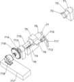
The rotating mechanism 7 comprises a first bearing seat 71, a top shaft 72, a clamping block 73, a first slide rail 74, a first slide block 75, a sleeve 76, a matching block 77, a first elastic member 78, a first bump 79, a first inserting block 710, a bent rod 711, a first clamping block 712, a second bearing seat 713, a transmission shaft 714, a square shaft 715, a first circular gear 716, a cushion 717 and a servo motor 718, wherein the first bearing seat 71 is fixedly connected to the left side of the top of the workbench 3, the top shaft 72 is rotatably arranged on the first bearing seat 71, the clamping block 73 is arranged at the right end of the top shaft 72, the first slide rail 74 is arranged on the right side of the top of the workbench 3, the first slide rail 74 is internally and slidably connected with the first slide block 75, the sleeve 76 is rotatably connected to the first slide block 75, the matching block 77 is arranged on the left side of the sleeve 76, the matching block 77 is matched with the clamping block 73, the first elastic member 78 is connected between the first slide rail 74 and the first slide block 75, the, the rear side of the first sliding block 75 is provided with a first protruding block 79, the left side of the first protruding block 79 is provided with a first inserting block 710, the top of the right side of the workbench 3 is provided with a bent rod 711, the bent rod 711 is positioned at the left rear side of the first sliding rail 74, the right side of the upper part of the bent rod 711 is symmetrically provided with first clamping blocks 712, the first clamping blocks 712 are matched with the first inserting blocks 710, the right side of the top of the workbench 3 is provided with a second bearing seat 713, the second bearing seat 713 is positioned at the right side of the first sliding rail 74, the second bearing seat 713 is rotatably connected with a transmission shaft 714, the left end of the transmission shaft 714 is provided with a square shaft 715, the sleeve 76 is slidably connected with the left end of the square shaft 715, the right end of the transmission shaft 714 is provided with a first circular gear 716, the top.
When people need to polish the rhinestone, the device can be used, firstly, people clamp one end of the rhinestone on the clamping block 73, then push the first slide block 75 to move leftwards, so that the first slide block 75 drives the sleeve 76, the matching block 77 and the first bump 79 to move leftwards, the first elastic piece 78 is stretched, the first bump 79 drives the first inserting block 710 to move leftwards, so that the first inserting block 710 is clamped by the first clamping block 712, so that the rhinestone is fixed, then people pull the polishing mechanism 8 part to move downwards, so that the polishing part of the polishing mechanism 8 moves downwards to be contacted with the rhinestone, then people start the servo motor 718, the output shaft of the servo motor 718 drives the transmission shaft 714 to rotate, the transmission shaft 714 drives the first round gear 716, the square shaft 715, the sleeve 76 and the matching block 77 to drive the rhinestone, the clamping block 73 and the top shaft 72 to rotate, and simultaneously the servo motor 718 drives the polishing part of the polishing mechanism 8 to move leftwards, polishing the rhinestone, when a polishing part of the polishing mechanism 8 moves leftwards to the maximum, polishing of the rhinestone is completed, people use tools to enable the first clamping block 712 to loosen the first inserting block 710, enable the first elastic piece 78 to reset, further drive the matching block 77 to move rightwards to reset, and loosen the rhinestone, at the moment, the polishing part of the polishing mechanism 8 moves upwards to reset, the rhinestone is loosened and rolls forwards along the rail 5 and then is blocked by the baffle 6, so that people can conveniently collect the rhinestone, when people need to polish the next rhinestone, the polishing part moves downwards, then the servo motor 718 is started to rotate reversely, the polishing part of the polishing mechanism 8 moves rightwards to reset, then the servo motor 718 can be closed, and the steps are repeated to quickly polish the next rhinestone.
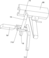
The polishing mechanism 8 comprises a first supporting block 81, a first sliding box 82, a second elastic piece 83, an N-shaped block 831, a second inserting block 84, a second clamping block 85, a step rod 86, a round block 87, a second sliding rail 88, a second supporting block 89, a second sliding box 810, a second sliding block 811, a screw rod 812, a nut block 813, a push rod 814, a second round gear 815, a handle 816 and a polisher 817, the first supporting block 81 is fixedly connected with the top of the rear side of the workbench 3 in a bilateral symmetry manner, the first sliding box 82 is arranged between the tops of the first supporting blocks 81, the second elastic piece 83 is uniformly arranged at the top of the first sliding box 82, a stretching spring of the second elastic piece 83 is connected between the bottom ends of the second elastic piece 83, the N-shaped block 831 slides in the first sliding box 82, the second inserting block 84 is uniformly arranged at the top of the N-shaped block 831, the second clamping block 85 is uniformly arranged at the bottom of the first sliding box 82, and the second clamping block 85 corresponds to the second inserting block 84, the second clamping block 85 is matched with the second inserting block 84, the middle of the N-shaped block 831 is connected with a stepped rod 86 in a sliding mode, the stepped rod 86 is matched with the second clamping block 85, the tail end of the stepped rod 86 is provided with a round block 87, the bottom of the N-shaped block 831 is provided with a second sliding rail 88, the left side and the right side of the top of the workbench 3 are symmetrically provided with second supporting blocks 89, the second supporting blocks 89 are respectively provided with a second sliding box 810, a second sliding block 811 is connected in the second sliding box 810 in a sliding mode, a lead screw 812 is connected between the second sliding blocks 811 in a rotating mode, a nut block 813 is connected in the second sliding rail 88 in a sliding mode, the nut block 813 is matched with the lead screw 812, the rear side of the nut block 813 is provided with a push rod 814, the push rod 814 is matched with the round block 87, the right end of the lead screw 812 is provided with a second round gear 815, the second round gear 815 is meshed with the first round gear 716.
Firstly, one end of a water drill bit is clamped on the clamping block 73, and pushes the first sliding block 75 to move leftwards, so that the water drill bit is fixed, then the handle 816 is pulled to move downwards, so that the second elastic piece 83 is stretched, the handle 816 drives the N-shaped block 831 to move downwards, the N-shaped block 831 drives the second sliding rail 88, the second inserting block 84, the nut block 813 and the stepped rod 86 to move downwards, the second inserting block 84 moves downwards and is clamped by the second clamping block 85, so that the position of the N-shaped block 831 is fixed, the nut block 813 moves downwards to drive the screw 812, the polisher 817 and the second circular gear 815 to move downwards, so that the polisher 817 is in contact with the water drill bit, the second circular gear 815 is in forward rotation and is meshed with the first circular gear 716, then one can start the servo motor 718, the servo motor output shaft 718 enables the first circular gear 716, the first circular gear 716 drives the second circular gear 815 to rotate reversely, and the second circular gear 815 drives the screw 812 to rotate reversely, the nut block 813 is enabled to move leftwards, the nut block 813 drives the ejector rod 814 and the polisher 817 to move leftwards, the polisher 817 moves leftwards to polish the water drill bit, when the ejector rod 814 is in contact with the round block 87, the water drill bit is polished completely, the ejector rod 814 drives the round block 87 and the stepped rod 86 to move leftwards, the stepped rod 86 moves leftwards to push open the second clamping block 85, the second clamping block 85 releases the second inserting block 84, the second elastic piece 83 is reset to drive the N-shaped block 831 to move upwards and reset, the N-shaped block 831 drives the polisher 817 to move upwards and far away from the water drill bit, meanwhile, the lead screw 812 drives the second round gear 815 to move upwards and far away from the first round gear 716, then, a user can use a tool to enable the first clamping block 712 to release the first inserting block 710, further loosen the water drill bit, so that the water drill bit slides to the baffle 6, then the user pulls the handle 816 to move downwards, so that the second round gear 815 is meshed with the first round gear 716, then the servo motor 718 is started to rotate reversely, so that the nut block 813 drives the polisher 817 and the ejector rod 814 to move rightwards to reset, and then the servo motor 718 is closed.
Example 2
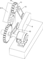
As shown in fig. 5 and 8, based on embodiment 1, a water drill polishing device further includes a speed adjusting box 9, a rotating shaft 10, a third circular gear 11, a first belt transmission device 12 and a second belt transmission device 13, the speed adjusting box 9 is disposed on the rear side of the top of the cushion block 717, the rotating shaft 10 is disposed on the upper portion of the second slide box 810 on the right side in a rotating manner, the third circular gear 11 is fixedly connected to the rotating shaft 10, the third circular gear 11 is engaged with the second circular gear 815, the first belt transmission device 12 is connected between the right end of the rotating shaft 10 and the output shaft of the speed adjusting box 9, and the second belt transmission device 13 is disposed between the output shaft of the servo motor 718 and the input shaft of the speed adjusting box 9.
When the water drill polishing is completed, the second circular gear 815 moves upwards to be meshed with the third circular gear 11, people start the servo motor 718 to rotate reversely, the output shaft of the servo motor 718 drives the second belt transmission device 13 and the input shaft of the speed regulating box 9 to rotate reversely, so that the output shaft of the speed regulating box 9 drives the first belt transmission device 12 to rotate reversely, the first belt transmission device 12 drives the rotating shaft 10 and the third circular gear 11 to rotate reversely, the third circular gear 11 drives the second circular gear 815 to rotate positively, so that the screw 812 rotates positively to drive the nut block 813 to move rightwards to reset, and thus the water drill can be polished more conveniently.
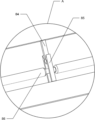
Still include second lug 14, connecting rod 15 and strut piece 16, second slide rail 88 right part rear side fixedly connected with second lug 14, second lug 14 rear side is equipped with connecting rod 15, and connecting rod 15 bottom is equipped with strut piece 16, strut piece 16 and the cooperation of first clamp splice 712.
When the second slide rail 88 moves upwards, the second slide rail 88 drives the second bump 14, the connecting rod 15 and the spreading block 16 to move upwards, so that the spreading block 16 spreads the first clamping block 712, the first inserting block 710 is loosened, and the polished rhinestone falls down, so that people do not need to use additional tools to open the first clamping block 712, and convenience is provided for people.
Finally, it should be noted that: although the present invention has been described in detail with reference to the foregoing embodiments, it will be apparent to those skilled in the art that modifications may be made to the embodiments or portions thereof without departing from the spirit and scope of the invention.
Claims (5)
1. The utility model provides a water drill burnishing device which characterized by includes:
the device comprises a base (1), wherein a plurality of first supporting columns (2) are arranged on the base (1);
the workbench (3) is arranged between the tops of the first supporting columns (2);
the top of the base (1) is symmetrically provided with second supporting columns (4);
the rails (5) are arranged on the second supporting columns (4), and the rails (5) are connected with the base (1);
the baffle (6) is arranged on one side, close to the rail (5), of the top of the base (1);
a rotating mechanism (7), wherein the rotating mechanism (7) is arranged on one side of the top of the workbench (3);
the polishing mechanism (8) is arranged on the other side of the top of the workbench (3).
2. A rhinestone head burnishing apparatus as defined in claim 1, wherein the rotating mechanism (7) comprises:
a first bearing seat (71), wherein one side of the top of the workbench (3) is provided with the first bearing seat (71);
the top shaft (72) is rotatably arranged on the first bearing seat (71);
the tail end of the top shaft (72) is provided with a clamping block (73);
the other side of the top of the workbench (3) is provided with a first sliding rail (74);
the first sliding block (75) is connected with the first sliding rail (74) in an inward sliding manner;
the sleeve (76) is rotatably connected to the first sliding block (75);
the matching block (77) is arranged on one side, close to the clamping block (73), of the sleeve (76), and the matching block (77) is matched with the clamping block (73);
the first elastic piece (78) is connected between the first sliding rail (74) and the first sliding block (75);
a first bump (79), wherein one side of the first sliding block (75) is provided with the first bump (79);
the first inserting block (710) is arranged on the first bump (79);
the top of one side, close to the first sliding rail (74), of the workbench (3) is provided with a bent rod (711);
the first clamping blocks (712) are symmetrically arranged on the bent rod (711), and the first clamping blocks (712) are matched with the first inserting blocks (710);
the top of the other side, close to the first sliding rail (74), of the workbench (3) is provided with a second bearing seat (713);
the transmission shaft (714) is rotatably connected on the second bearing seat (713);
the transmission shaft (714) is provided with a square shaft (715) at one end, and the sleeve (76) is connected with the tail end of the square shaft (715) in a sliding manner;
the other end of the transmission shaft (714) is provided with a first circular gear (716);
the top of the side, close to the first circular gear (716), of the workbench (3) is provided with a cushion block (717);
the servo motor (718) is installed on the servo motor (718) and the cushion block (717), and an output shaft of the servo motor (718) is connected with the transmission shaft (714).
3. A rhinestone head polishing apparatus according to claim 2, wherein the polishing mechanism (8) comprises:
the top of the workbench (3) is symmetrically provided with the first supporting blocks (81);
the first sliding box (82) is arranged between the tops of the first supporting blocks (81);
the second elastic pieces (83) are uniformly arranged at the top in the first sliding box (82);
the N-shaped block (831) is connected between the tail ends of the second elastic pieces (83);
the second inserting blocks (84) are uniformly arranged at the inner tops of the N-shaped blocks (831);
the second clamping blocks (85) are uniformly arranged at the bottom in the first sliding box (82), and the second clamping blocks (85) are matched with the second inserting blocks (84);
the ladder rod (86) is connected with the N-shaped block (831) in a sliding mode, and the ladder rod (86) is matched with the second clamping block (85);
the round block (87) is arranged at the tail end of the step rod (86);
the bottom of the N-shaped block (831) is provided with a second sliding rail (88);
the top of one side, close to the first supporting block (81), of the workbench (3) is symmetrically provided with the second supporting block (89);
the second sliding boxes (810) are arranged on the second supporting blocks (89);
a second slider (811), wherein the second slider (811) is connected with the second sliding box (810) in a sliding way;
the screw rod (812) is rotatably connected between the second sliding blocks (811);
the second sliding rail (88) is internally and slidably connected with a nut block (813), and the nut block (813) is matched with the screw rod (812);
the ejector rod (814) is arranged on the nut block (813), and the ejector rod (814) is matched with the round block (87);
one end of the screw rod (812) close to the cushion block (717) is provided with a second circular gear (815), and the second circular gear (815) is meshed with the first circular gear (716);
the handles (816) are symmetrically arranged on the handle (816) and the N-shaped block (831);
a polisher (817) is arranged on the nut block (813), and the polisher (817) is arranged on the nut block (813).
4. A rhinestone head polishing apparatus according to claim 3, further comprising:
the speed regulating box (9) is arranged on the cushion block (717);
the rotating shaft (10) is rotatably arranged on the second sliding box (810) provided with the second circular gear (815);
the third round gear (11) is arranged on the rotating shaft (10), and the third round gear (11) is meshed with the second round gear (815);
a first belt transmission device (12) is connected between the tail end of the rotating shaft (10) and an output shaft of the speed regulating box (9);
and a second belt transmission device (13) is arranged between the output shaft of the servo motor (718) and the input shaft of the speed regulating box (9).
5. The rhinestone head polishing apparatus according to claim 4, further comprising:
a second bump (14) is arranged on one side, close to the ejector rod (814), of the second slide rail (88);
the connecting rod (15) is arranged on the second bump (14);
the opening block (16) is arranged on the connecting rod (15), and the opening block (16) is matched with the first clamping block (712).
Priority Applications (1)
| Application Number | Priority Date | Filing Date | Title |
|---|---|---|---|
| CN202011014143.XA CN112157491A (en) | 2020-09-24 | 2020-09-24 | Water drill burnishing device |
Applications Claiming Priority (1)
| Application Number | Priority Date | Filing Date | Title |
|---|---|---|---|
| CN202011014143.XA CN112157491A (en) | 2020-09-24 | 2020-09-24 | Water drill burnishing device |
Publications (1)
| Publication Number | Publication Date |
|---|---|
| CN112157491A true CN112157491A (en) | 2021-01-01 |
Family
ID=73863947
Family Applications (1)
| Application Number | Title | Priority Date | Filing Date |
|---|---|---|---|
| CN202011014143.XA Pending CN112157491A (en) | 2020-09-24 | 2020-09-24 | Water drill burnishing device |
Country Status (1)
| Country | Link |
|---|---|
| CN (1) | CN112157491A (en) |
Cited By (1)
| Publication number | Priority date | Publication date | Assignee | Title |
|---|---|---|---|---|
| CN112975600A (en) * | 2021-03-17 | 2021-06-18 | 夏安东 | Quick water drill burnishing device |
Citations (4)
| Publication number | Priority date | Publication date | Assignee | Title |
|---|---|---|---|---|
| KR20110101733A (en) * | 2010-03-09 | 2011-09-16 | 주식회사 관음정밀 | A re-sharpening apparatus of drill bit and re-sharpening method using thereof |
| CN105619213A (en) * | 2016-01-07 | 2016-06-01 | 温州大学 | Automatic polishing system for cylindrical workpiece |
| CN209954432U (en) * | 2019-04-18 | 2020-01-17 | 惠安县盛源五金店 | Burnishing device suitable for cylinder work piece |
| CN111687735A (en) * | 2020-05-11 | 2020-09-22 | 龙红辉 | Water drill burnishing device |
-
2020
- 2020-09-24 CN CN202011014143.XA patent/CN112157491A/en active Pending
Patent Citations (4)
| Publication number | Priority date | Publication date | Assignee | Title |
|---|---|---|---|---|
| KR20110101733A (en) * | 2010-03-09 | 2011-09-16 | 주식회사 관음정밀 | A re-sharpening apparatus of drill bit and re-sharpening method using thereof |
| CN105619213A (en) * | 2016-01-07 | 2016-06-01 | 温州大学 | Automatic polishing system for cylindrical workpiece |
| CN209954432U (en) * | 2019-04-18 | 2020-01-17 | 惠安县盛源五金店 | Burnishing device suitable for cylinder work piece |
| CN111687735A (en) * | 2020-05-11 | 2020-09-22 | 龙红辉 | Water drill burnishing device |
Cited By (1)
| Publication number | Priority date | Publication date | Assignee | Title |
|---|---|---|---|---|
| CN112975600A (en) * | 2021-03-17 | 2021-06-18 | 夏安东 | Quick water drill burnishing device |
Similar Documents
| Publication | Publication Date | Title |
|---|---|---|
| CN114378584B (en) | Cutting device is used in metal pipeline production | |
| CN215036218U (en) | Stainless steel parts machining is with equipment of polishing convenient to adjust | |
| CN112428038A (en) | Sanding and polishing equipment for steel basin | |
| CN219987064U (en) | Gear machining grinding device | |
| CN112091751A (en) | Vertical marble material equipment of polishing | |
| CN112476181A (en) | Automatic polishing device for automobile square parts | |
| CN112157491A (en) | Water drill burnishing device | |
| CN112518457A (en) | Workbench plane polishing equipment for milling machine | |
| CN115609458A (en) | Steel polishing device for building engineering | |
| CN112621535B (en) | Office chair base polishing equipment | |
| CN112171427A (en) | Be used for lens edge machining and forming equipment | |
| CN212762539U (en) | Polishing sheet device capable of assisting in cleaning dust | |
| CN220994026U (en) | Injection mold polishing machine capable of moving polishing | |
| CN112658950A (en) | Wood burnishing device for furniture processing | |
| CN112476087A (en) | Based on quick grinding device of wooden toy gyro wheel | |
| CN215942535U (en) | Polishing device for surface of laser radiator shell | |
| CN114310604B (en) | Commercial pipe inner wall equipment of polishing | |
| CN214024937U (en) | Burr grinding device is used in metal product processing | |
| CN113182956B (en) | Neurosurgery operation box bottom polishing equipment of polishing | |
| CN221696471U (en) | Self-spacing surface polishing equipment | |
| CN112388471A (en) | A burnishing and polishing equipment for circular plank surface | |
| CN221621824U (en) | Surface polishing device for processing die steel fittings | |
| CN112388440B (en) | Equipment for polishing round wood into beads | |
| CN221270770U (en) | Polishing device for screw rod | |
| CN221159832U (en) | Nonferrous metal polishing device |
Legal Events
| Date | Code | Title | Description |
|---|---|---|---|
| PB01 | Publication | ||
| PB01 | Publication | ||
| SE01 | Entry into force of request for substantive examination | ||
| SE01 | Entry into force of request for substantive examination | ||
| WD01 | Invention patent application deemed withdrawn after publication | ||
| WD01 | Invention patent application deemed withdrawn after publication |
Application publication date: 20210101 |