CN112145603A - Vehicle shock absorber, vehicle suspension structure and vehicle - Google Patents
Vehicle shock absorber, vehicle suspension structure and vehicle Download PDFInfo
- Publication number
- CN112145603A CN112145603A CN201910561675.6A CN201910561675A CN112145603A CN 112145603 A CN112145603 A CN 112145603A CN 201910561675 A CN201910561675 A CN 201910561675A CN 112145603 A CN112145603 A CN 112145603A
- Authority
- CN
- China
- Prior art keywords
- vehicle
- valve
- attitude control
- cylinder
- shock absorber
- Prior art date
- Legal status (The legal status is an assumption and is not a legal conclusion. Google has not performed a legal analysis and makes no representation as to the accuracy of the status listed.)
- Pending
Links
Images


Classifications
-
- F—MECHANICAL ENGINEERING; LIGHTING; HEATING; WEAPONS; BLASTING
- F16—ENGINEERING ELEMENTS AND UNITS; GENERAL MEASURES FOR PRODUCING AND MAINTAINING EFFECTIVE FUNCTIONING OF MACHINES OR INSTALLATIONS; THERMAL INSULATION IN GENERAL
- F16F—SPRINGS; SHOCK-ABSORBERS; MEANS FOR DAMPING VIBRATION
- F16F9/00—Springs, vibration-dampers, shock-absorbers, or similarly-constructed movement-dampers using a fluid or the equivalent as damping medium
- F16F9/06—Springs, vibration-dampers, shock-absorbers, or similarly-constructed movement-dampers using a fluid or the equivalent as damping medium using both gas and liquid
-
- B—PERFORMING OPERATIONS; TRANSPORTING
- B60—VEHICLES IN GENERAL
- B60G—VEHICLE SUSPENSION ARRANGEMENTS
- B60G13/00—Resilient suspensions characterised by arrangement, location or type of vibration dampers
- B60G13/02—Resilient suspensions characterised by arrangement, location or type of vibration dampers having dampers dissipating energy, e.g. frictionally
- B60G13/06—Resilient suspensions characterised by arrangement, location or type of vibration dampers having dampers dissipating energy, e.g. frictionally of fluid type
- B60G13/08—Resilient suspensions characterised by arrangement, location or type of vibration dampers having dampers dissipating energy, e.g. frictionally of fluid type hydraulic
-
- B—PERFORMING OPERATIONS; TRANSPORTING
- B60—VEHICLES IN GENERAL
- B60G—VEHICLE SUSPENSION ARRANGEMENTS
- B60G17/00—Resilient suspensions having means for adjusting the spring or vibration-damper characteristics, for regulating the distance between a supporting surface and a sprung part of vehicle or for locking suspension during use to meet varying vehicular or surface conditions, e.g. due to speed or load
- B60G17/06—Characteristics of dampers, e.g. mechanical dampers
- B60G17/08—Characteristics of fluid dampers
-
- B—PERFORMING OPERATIONS; TRANSPORTING
- B60—VEHICLES IN GENERAL
- B60G—VEHICLE SUSPENSION ARRANGEMENTS
- B60G21/00—Interconnection systems for two or more resiliently-suspended wheels, e.g. for stabilising a vehicle body with respect to acceleration, deceleration or centrifugal forces
- B60G21/02—Interconnection systems for two or more resiliently-suspended wheels, e.g. for stabilising a vehicle body with respect to acceleration, deceleration or centrifugal forces permanently interconnected
- B60G21/04—Interconnection systems for two or more resiliently-suspended wheels, e.g. for stabilising a vehicle body with respect to acceleration, deceleration or centrifugal forces permanently interconnected mechanically
- B60G21/05—Interconnection systems for two or more resiliently-suspended wheels, e.g. for stabilising a vehicle body with respect to acceleration, deceleration or centrifugal forces permanently interconnected mechanically between wheels on the same axle but on different sides of the vehicle, i.e. the left and right wheel suspensions being interconnected
- B60G21/055—Stabiliser bars
- B60G21/0551—Mounting means therefor
-
- B—PERFORMING OPERATIONS; TRANSPORTING
- B60—VEHICLES IN GENERAL
- B60G—VEHICLE SUSPENSION ARRANGEMENTS
- B60G7/00—Pivoted suspension arms; Accessories thereof
- B60G7/006—Attaching arms to sprung or unsprung part of vehicle, characterised by comprising attachment means controlled by an external actuator, e.g. a fluid or electrical motor
-
- B—PERFORMING OPERATIONS; TRANSPORTING
- B62—LAND VEHICLES FOR TRAVELLING OTHERWISE THAN ON RAILS
- B62D—MOTOR VEHICLES; TRAILERS
- B62D7/00—Steering linkage; Stub axles or their mountings
- B62D7/18—Steering knuckles; King pins
-
- B—PERFORMING OPERATIONS; TRANSPORTING
- B62—LAND VEHICLES FOR TRAVELLING OTHERWISE THAN ON RAILS
- B62D—MOTOR VEHICLES; TRAILERS
- B62D7/00—Steering linkage; Stub axles or their mountings
- B62D7/20—Links, e.g. track rods
-
- F—MECHANICAL ENGINEERING; LIGHTING; HEATING; WEAPONS; BLASTING
- F16—ENGINEERING ELEMENTS AND UNITS; GENERAL MEASURES FOR PRODUCING AND MAINTAINING EFFECTIVE FUNCTIONING OF MACHINES OR INSTALLATIONS; THERMAL INSULATION IN GENERAL
- F16F—SPRINGS; SHOCK-ABSORBERS; MEANS FOR DAMPING VIBRATION
- F16F9/00—Springs, vibration-dampers, shock-absorbers, or similarly-constructed movement-dampers using a fluid or the equivalent as damping medium
- F16F9/32—Details
- F16F9/34—Special valve constructions; Shape or construction of throttling passages
- F16F9/3405—Throttling passages in or on piston body, e.g. slots
Abstract
The invention is suitable for the technical field of vehicle structures, and discloses a vehicle shock absorber, a vehicle suspension structure and a vehicle. The vehicle shock absorber comprises a cylinder, a damping valve, a piston rod and a vehicle attitude control valve, wherein the vehicle attitude control valve is arranged in the cylinder and is provided with a communicating channel communicated with two sides of the vehicle attitude control valve, a control part which moves when the acceleration of a vehicle in a set direction is greater than a set value and partially or completely blocks the communicating channel is arranged in the vehicle attitude control valve, and a resetting part is also arranged in the vehicle attitude control valve. The vehicle suspension structure and the vehicle are provided with the vehicle shock absorber. The vehicle suspension structure can avoid the occurrence of unexpected pitching and rolling motions of a vehicle, improves the control capability of the vehicle body, has better driving quality, simple and reliable structure, does not need complex hydraulic and electronic control systems, and has low application cost and low failure rate.
Description
Technical Field
The invention belongs to the technical field of vehicle structures, and particularly relates to a vehicle shock absorber, a vehicle suspension structure and a vehicle.
Background
When the vehicle brakes, the load is transferred to the front axle, the front wheels are pressed to the vehicle body, the shock absorbers in the suspension structure at the front wheels are pressed, the rear wheels are pulled away from the vehicle body, the shock absorbers in the suspension structure at the rear wheels are pulled, and the vehicle body generates a nodding angle; when the vehicle accelerates, the load is transferred to the rear axle, the rear wheels are pressed to the vehicle body, the front wheels are pulled away from the vehicle body, and the vehicle body generates a lifting angle; the nodding angle and the uplifting angle are referred to as pitching motion of the vehicle body. When the vehicle turns, the load is transferred to the outer wheels, the outer wheels are pressed toward the vehicle body, the shock absorber is compressed in the suspension structure at the outer wheels, the inner wheels are pulled away from the vehicle body, the shock absorber is pulled in the suspension structure at the inner wheels, and the vehicle body generates a roll angle, which is called roll motion. To ensure comfort, the stiffness of the wheels relative to vertical movement with respect to the body is low, which results in undesirable pitch and roll movements of the body.
In order to eliminate the rolling motion, the vehicle is generally provided with a stabilizer bar, which serves to connect the left and right wheels together, and to reduce the relative motion (outer compression, inner tension) of the left and right wheels during rolling by the stabilizer bar, thereby achieving the function of controlling the rolling of the vehicle body. However, when the suspension with the stabilizer bar passes through the road surface at one side, the rigidity of the vertical movement between the wheel and the vehicle body is obviously increased, which is not favorable for the smoothness.
The pitching motion of the vehicle is difficult to control, and is generally realized by limiting the motion stroke between the wheels and the vehicle body, but the smoothness is not favorable, and a small part of vehicles are added with a complex hydraulic or electronic control system for eliminating the pitching motion, so that the cost is high, and the failure rate is high.
Disclosure of Invention
The present invention is directed to at least one of the above technical problems, and provides a vehicle shock absorber, a vehicle suspension structure, and a vehicle, which can prevent the vehicle from generating undesirable pitching and rolling motions, improve the vehicle body control capability, eliminate the need for complex hydraulic and electronic control systems, and have low application cost and low failure rate.
The technical scheme of the invention is as follows: a vehicle shock absorber comprises a cylinder, a damping valve and a piston rod, wherein the damping valve is arranged in the cylinder, one end of the piston rod is connected to the damping valve, the other end of the piston rod extends out of one end of the cylinder, a shock absorption medium is arranged in the cylinder, and the damping valve is provided with a damping hole through which the shock absorption medium flows;
the vehicle shock absorber further comprises a vehicle attitude control valve, the vehicle attitude control valve is arranged in the cylinder and provided with a communication channel communicated with two sides of the vehicle attitude control valve, a control piece which moves when the acceleration of the vehicle in the set direction is greater than a set value and partially or completely blocks the communication channel is arranged in the vehicle attitude control valve, and a reset piece which is used for resetting the control piece when the acceleration in the set direction is eliminated is also arranged in the vehicle attitude control valve.
Optionally, vehicle attitude control valve is including the valve body that has the valve pocket, the periphery of valve body with the inner wall of barrel pastes mutually, the one side of valve body is provided with first through-hole, the another side of valve body is provided with the second through-hole, first through-hole, second through-hole all communicate in the valve pocket forms the intercommunication passageway, the control set up in the valve pocket, reset the piece set up respectively in the both sides that the control is relative and support the top in the control.
Optionally, there are first locating part and second locating part in valve chamber threaded connection or the fixing clip is equipped with, first locating part and the coaxial interval setting in opposite directions of second locating part, first locating part has first flow passage hole, second locating part has second flow passage hole, the control set up in first locating part with between the second locating part, just the control under the reset state with the valve chamber has the clearance, the piece that resets includes first spring and second spring, first spring support in first locating part with one side of control, the second spring support in the second locating part with the opposite side of control.
Optionally, the control member is spherical, or the control member is cylindrical and two ends of the control member are spherical.
Optionally, the valve body is discoid, the valve chamber is along the radial through setting of valve body, the periphery cover of valve body is equipped with and is used for the shutoff the sealed ring of valve chamber tip, perhaps, the both ends of valve chamber are provided with and are used for the shutoff the end cap of valve chamber tip.
Optionally, one vehicle attitude control valve is provided, and the movement direction of the control member in the vehicle attitude control valve is the same as or perpendicular to the forward direction of the vehicle.
Alternatively, the vehicle attitude control valves are provided in two, two of the vehicle attitude control valves are provided one above the other, and one of the vehicle attitude control valves is a pitch attitude control valve in which a moving direction of the control member is the same as a forward direction of the vehicle, and the other of the vehicle attitude control valves is a roll attitude control valve in which a moving direction of the control member is perpendicular to a forward direction of the vehicle.
Optionally, the upper end of the piston rod penetrates through the upper end of the cylinder body, the cylinder body comprises an outer cylinder and an inner cylinder, the inner cylinder is fixedly arranged in the outer cylinder, the inner cylinder is provided with an inner cavity, an interlayer cavity is arranged between the outer cylinder and the inner cylinder, the damping valve and the vehicle attitude control valve are both arranged in the inner cavity, the damping valve can slide along the axis of the inner cylinder, the vehicle attitude control valve is fixedly connected to the inner cylinder, the interlayer cavity is communicated with the inner cavity through a communication hole, the communication hole is close to or located at the lower end of the inner cylinder, the upper part of the interlayer cavity is provided with compressed gas, the lower part of the interlayer cavity and the inner cavity are provided with the damping medium, the damping valve and one or two vehicle attitude control valves are arranged in the inner cylinder at an upper-lower interval and divide the inner cavity of the inner cylinder into a plurality of sub, the damping hole or the communication channel is arranged between the adjacent sub-cavities.
The invention also provides a vehicle suspension structure which is provided with the vehicle shock absorber.
Optionally, the vehicle suspension structure is a cross-arm suspension structure, a double-wishbone suspension structure, a multi-link suspension structure, a trailing-arm suspension structure, or a macpherson suspension structure.
Optionally, the vehicle suspension structure comprises a knuckle, a steering rod and a swing arm, the knuckle being connected to the cylinder of the vehicle shock absorber, the steering rod and the swing arm, respectively.
Optionally, the vehicle suspension structure further comprises a stabilizer link and a stabilizer bar with two ends connected to the vehicle suspension structure, one end of the stabilizer link is rotatably connected to the cylinder, and the other end of the stabilizer link is rotatably connected to the end of the stabilizer bar.
The invention also provides a vehicle which is provided with the vehicle shock absorber.
The invention provides a vehicle shock absorber, a vehicle suspension structure and a vehicle, wherein a vehicle attitude control valve (comprising a roll attitude control valve or/and a pitch attitude control valve) is arranged in the shock absorber, when the vehicle has longitudinal acceleration (acceleration and braking) or lateral acceleration (steering), the roll attitude control valve and the pitch attitude control valve can block an oil passage to limit the extension and contraction of the shock absorber, and when the vehicle brakes, accelerates or turns, the relative vertical motion between a wheel and a vehicle body is limited, the vehicle attitude does not change, so that the relative vertical motion between the wheel and the vehicle body is limited, the aim of controlling the motion of the vehicle body is fulfilled, the unexpected pitch and roll motion of the vehicle can be avoided, the vehicle body control capability is improved, the driving quality is better, the structure is simple and reliable, a complex hydraulic and electronic control system is not needed, and the application cost is low, The failure rate is low.
Drawings
In order to more clearly illustrate the technical solutions in the embodiments of the present invention, the drawings needed to be used in the embodiments will be briefly described below, and it is obvious that the drawings in the following description are only some embodiments of the present invention, and it is obvious for those skilled in the art that other drawings can be obtained according to these drawings without creative efforts.
FIG. 1 is a partial perspective view of a vehicle suspension arrangement provided by an embodiment of the present invention;
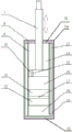
FIG. 2 is a cross-sectional schematic view of a vehicle shock absorber in a vehicle suspension configuration provided in accordance with an embodiment of the present invention;
fig. 3 is a schematic cross-sectional view of a vehicle attitude control valve in a vehicle shock absorber according to an embodiment of the present invention.
Detailed Description
In order to make the objects, technical solutions and advantages of the present invention more apparent, the present invention is described in further detail below with reference to the accompanying drawings and embodiments. It should be understood that the specific embodiments described herein are merely illustrative of the invention and are not intended to limit the invention.
It should be noted that the terms "disposed" and "connected" should be interpreted broadly, and may be, for example, directly disposed or connected, or indirectly disposed or connected through intervening elements or intervening structures.
In addition, in the embodiments of the present invention, if there are terms of orientation or positional relationship indicated by "longitudinal", "lateral", "length", "width", "thickness", "upper", "lower", "front", "rear", "left", "right", "vertical", "horizontal", "top", "bottom", "inner", "outer", etc., it is only for convenience of describing the present invention and simplifying the description, but not for indicating or implying that the structure, feature, device or element referred to must have a specific orientation or positional relationship, nor must be constructed and operated in a specific orientation, and thus should not be construed as limiting the present invention. In the description of the present invention, "a plurality" means two or more unless otherwise specified.
The various features and embodiments described in the embodiments may be combined in any suitable manner, for example, different embodiments may be formed by combining different features/embodiments, and in order to avoid unnecessary repetition, various possible combinations of features/embodiments in the present invention will not be described in detail.
As shown in fig. 1 to 3, a vehicle shock absorber 1 according to an embodiment of the present invention includes a cylinder 30, a damping valve 10 and a piston rod 7, wherein the damping valve 10 is disposed in the cylinder 30, and a damping medium is disposed in the cylinder 30, and the damping medium may be damping oil (hydraulic oil) or the like. The damping valve 10 is provided with a damping orifice 15 for the damping medium to flow through. The periphery of the damping valve 10 is in sliding fit with the inner wall of the cylinder 30, that is, the damping valve 10 can slide along the axial direction of the cylinder 30, the damping valve 10 can be in a piston shape, and the damping medium flows through the damping hole 15 to realize damping. One end of the piston rod 7 is connected to one side of the damping valve 10, and the other end of the piston rod 7 extends out of one end of the cylinder 30.
The vehicle shock absorber 1 further includes a vehicle attitude control valve which can use a pitch attitude control valve 11 and a roll attitude control valve 12 depending on different mounting directions, the pitch attitude control valve 11 and the roll attitude control valve 12 being identical in structure and differing only in mounting direction. The vehicle attitude control valve is arranged in the barrel 30 and is provided with a communicating channel communicated with two sides of the vehicle attitude control valve, a control piece 24 which moves when the acceleration of the vehicle in the set direction is greater than a set value and partially or completely blocks the communicating channel is arranged in the vehicle attitude control valve, and a reset piece which is used for resetting the control piece 24 when the acceleration in the set direction is eliminated is also arranged in the vehicle attitude control valve. When the acceleration of the vehicle in the set direction is greater than the set value, the control part 24 moves under the action of inertia and partially or completely blocks the communication channel, so that the movement of the damping valve 10 is blocked, the vehicle posture is resisted to be greatly changed, the vehicle can be prevented from generating unexpected pitching and rolling movements, the vehicle body control capability is improved, the driving quality is good, the structure is simple and reliable, a complex hydraulic and electronic control system is not needed, the application cost is low, and the failure rate is low.
In this embodiment, the upper end of the piston rod 7 penetrates the upper end of the cylinder 30, the cylinder 30 includes an outer cylinder 8 and an inner cylinder 9, the upper end of the outer cylinder 8 has an upper end cover 31, the lower end of the outer cylinder 8 has a lower end cover 32, and the piston rod 7 penetrates the upper end cover 31 in a sealing manner. The inner cylinder 9 is fixedly disposed in the outer cylinder 8, the inner cylinder 9 has an inner cavity, and an upper end of the inner cylinder 9 can be hermetically connected (e.g., welded) to an inner side of the upper end cover 31. The damping valve 10 and the vehicle attitude control valve are arranged in the inner cavity, the damping valve can slide along the axis of the inner cylinder 9, and the vehicle attitude control valve can be fixedly connected to the inner cylinder 9. Namely, the outer side wall of the damping valve 10 can be matched with the inner side wall of the inner cylinder 9 in a small interference fit mode, the damping valve 10 can slide along the axis of the inner cylinder 9, and the vehicle attitude control valve cannot slide along the axis of the inner cylinder 9. The urceolus 8 with the intermediate coat chamber 13 has between the inner tube 9, the intermediate coat chamber 13 pass through the intercommunicating pore 19 with the inner chamber intercommunication, intercommunicating pore 19 is close to or is located the lower extreme of inner tube 9, the upper portion in intermediate coat chamber 13 sets up to compressed gas, the lower part in intermediate coat chamber 13 reaches be provided with in the inner chamber damping medium, except that the upper portion in intermediate coat chamber 13 sets up to compressed gas (high pressure gas) in barrel 30 promptly, all the other cavities are full of damping medium (damping oil). The vehicle attitude control valve is located between the communication hole 19 and the damping valve 10. In the present embodiment, the damping valve 10 is located at the upper side of the vehicle attitude control valve, and the communication hole 19 is located at the lower side of the vehicle attitude control valve.
Specifically, the vehicle attitude control valve comprises a valve body 21 with a valve cavity 36, sub-cavities are formed on two sides of the valve body 21 and filled with damping media, the shape of the vehicle attitude control valve can be the same as that of the damping valve 10, the vehicle attitude control valve is fixedly connected with the cylinder 30, and the vehicle attitude control valve cannot slide along the axis of the cylinder 30. The outer periphery of the valve body 21 is attached to the inner wall of the cylinder 30, one surface (for example, the upper end surface) of the valve body 21 is provided with a first through hole 27, the other surface (the lower end surface) of the valve body 21 is provided with a second through hole 28, both the first through hole 27 and the second through hole 28 are communicated with the valve cavity 36 to form the communication passage, the damping medium can flow into the valve cavity 36 from the first through hole 27 of the vehicle attitude control valve and flow out of the second through hole 28, and the damping medium can also flow into the valve cavity 36 from the second through hole 28 of the vehicle attitude control valve and flow out of the first through hole 27. The control member 24 is disposed in the valve cavity 36, and the reset member is provided with two parts which are respectively disposed on two opposite sides of the control member 24 and abut against the control member 24, so that the valve cavity 36 is kept smooth. The valve chamber 36 may have a diameter larger than the outer dimension of the control member 24, and the restoring member may be an elastic member. When the vehicle is accelerated in a set direction, the mass of the control member 24 is m, the force applied to the control member 24 is F ═ m × a, and F is greater than the reset force applied to the control member 24 by the reset member, the control member 24 moves in the set direction along the valve cavity 36, so that the valve cavity 36 can be partially blocked or completely blocked, the resistance of the damping oil flowing through the valve cavity 36 is increased sharply, or the damping oil cannot flow through the valve cavity 36, so that the movement of the damping valve 10 is suppressed, and the vehicle posture is controlled.
Specifically, the valve cavity 36 may be threadedly connected or fixedly clamped with a first limiting member 22 and a second limiting member 26, the first limiting member 22 and the second limiting member 26 are coaxially disposed in opposite directions at an interval, the first limiting member 22 has a first flow passage hole 37, the second limiting member 26 has a second flow passage hole 38, and the first flow passage hole 37 and the second flow passage hole 38 are coaxially disposed in opposite directions at an interval. The control member 24 is disposed between the first limiting member 22 and the second limiting member 26, when the control member 24 moves to the first flow passage hole 37, the first flow passage hole 37 may be closed, and at this time, the flow passage is closed, and when the control member 24 moves to the second flow passage hole 38, the second flow passage hole 38 may be closed, and at this time, the flow passage will also be closed. And the control member 24 has a clearance with the valve chamber 36 in a reset state, the reset member comprises a first spring 23 and a second spring 25, and the first spring 23 and the second spring 25 can be conical springs. The first spring 23 abuts against one side of the first limiting member 22 and the control member 24, and the second spring 25 abuts against the other side of the second limiting member 26 and the control member 24.
In a specific application, the control member 24 may be spherical, or the control member 24 may be cylindrical and have two spherical ends. In the present embodiment, the control member 24 is a metal ball, for example, a steel ball is used as a sealing ball.
Specifically, the valve body 21 may have a disk shape (piston shape), the valve chamber 36 may be provided to penetrate in a radial direction of the valve body 21, and the first stopper 22 and the second stopper 26 may be attached to both ends of the valve chamber 36. In this embodiment, at least two ends of the valve cavity 36 are provided with internal threads, and the outer sides of the first limiting member 22 and the second limiting member 26 are provided with external threads matched with the internal threads. The first retaining member 22 and the second retaining member 26 may be in the form of bolts having axial openings. The periphery of the valve body 21 is sleeved with a sealing ring 20 for plugging the end part of the valve cavity 36, or plugs for plugging the end part of the valve cavity 36 are arranged at two ends of the valve cavity 36.
Specifically, there is one vehicle attitude control valve, and the movement direction of the control member 24 in the vehicle attitude control valve is the same as or perpendicular to the forward direction of the vehicle. The installation direction of the vehicle attitude control valve is the moving direction of the control member 24, i.e., the axial direction of the valve chamber 36, and can also be defined as the axial directions of the first and second flow passage holes 37, 38. When the installation direction of the vehicle attitude control valve faces the front and rear direction of the vehicle, and when the vehicle suddenly decelerates or accelerates, the acceleration value is larger than a set value, the control part 24 correspondingly moves forwards and backwards to block the flow passage, so that the movement of the damping valve 10 is limited, the nodding and the rising of the vehicle can be further inhibited, and the influence of the vehicle attitude on the driving comfort caused by overlarge change can be prevented. When the installation direction of the vehicle attitude control valve faces the left and right directions of the vehicle, when the turning speed of the vehicle is too high and the acceleration value is greater than a set value, the control part 24 correspondingly moves left and right to block the flow channel, so that the movement of the damping valve 10 is limited, the side inclination of the vehicle can be restrained, and the influence of the too large change of the vehicle attitude on the driving comfort can be prevented.
Specifically, the vehicle attitude control valve is provided with two vehicle attitude control valves, the two vehicle attitude control valves are arranged up and down, one of the vehicle attitude control valves is the pitch attitude control valve 11, the movement direction of the check member 24 in the pitch attitude control valve 11 is the same as the forward direction of the vehicle, the installation direction of the pitch attitude control valve 11 is toward the vehicle front-rear direction, that is, the axial direction of the valve chamber 36 (the axial direction of the first flow passage hole 37 and the second flow passage hole 38) is the same as the vehicle front-rear direction, and the check member 24 can block the flow passage when moving forward and backward relative to the front vehicle. The other of the vehicle posture control valves is a roll posture control valve 12, and the movement direction of the control member 24 in the roll posture control valve 12 is perpendicular to the forward direction of the vehicle. The roll attitude control valve 12 is mounted in a direction toward the vehicle left-right direction, that is, the axial direction of the valve chamber 36 (the axial direction of the first and second flow passage holes 37, 38) coincides with the vehicle left-right direction, and the control member 24 can block the flow passage when moving left and right relative to the front vehicle.
Specifically, the damping valve 10, one or two vehicle attitude control valves are arranged in the inner cylinder 9 at an interval from top to bottom and divide an inner cavity of the inner cylinder 9 into a plurality of sub-cavities, and the damping hole 15 or the communication channel is arranged between adjacent sub-cavities.
In the present embodiment, taking two vehicle attitude control valves (one roll attitude control valve 12 and one pitch attitude control valve 11) as an example, the damping valve 10, the pitch attitude control valve 11 and the roll attitude control valve 12 are disposed in the inner cylinder 9 of the cylinder 30 at intervals up and down, a first sub-chamber 14 is formed between the upper end of the damping valve 10 and the upper end cap 31 of the cylinder 30, a second sub-chamber 16 is formed between the lower end of the damping valve 10 and the upper end of the pitch attitude control valve 11, a third sub-chamber 17 is formed between the lower end of the pitch attitude control valve 11 and the upper end of the roll attitude control valve 12, a fourth sub-chamber 18 is formed between the lower end of the roll attitude control valve 12 and the lower end cap 32 of the cylinder 30, and the fourth sub-chamber 18 is communicated with the interlayer chamber 13 between the outer cylinder 8 and the.
The first sub-cavity 14, the second sub-cavity 16, the third sub-cavity 17 and the fourth sub-cavity 18 are filled with oil (damping medium), the lower half part of the interlayer cavity 13 is filled with the oil, and the upper half part of the interlayer cavity 13 is filled with high-pressure gas. When the piston rod 7 of the shock absorber 1 extends and contracts, oil between the first sub-chamber 14 and the second sub-chamber 16 flows through the orifice 15 of the damping valve 10 of the shock absorber 1. Meanwhile, when the piston rod 7 of the shock absorber 1 extends and contracts, the volume of the piston rod 7 in the shock absorber 1 is different, taking compression as an example, the volume of the piston rod 7 in the inner cylinder 9 is increased, oil flows into the interlayer cavity 13 from the second sub-cavity 16, the flow channel of the pitch attitude control valve 11, the third sub-cavity 17, the flow channel of the roll attitude control, the fourth sub-cavity 18 and the communication hole 19 in sequence, the interlayer cavity 13 contains the extruded oil and the air pressure is increased, and the piston rod 7 is opposite to the interlayer cavity 13 in extension.
When the vehicle normally runs, oil on two sides of the pitching attitude control valve 11 is communicated through a first through hole 27 and a second through hole 28 through a path shown in fig. 3, oil pressure in the second sub-cavity 16 and the third sub-cavity 17 is consistent all the time, and the same is true for the rolling attitude control valve 12, the oil pressure in the third sub-cavity 17 is consistent all the time with that in the fourth sub-cavity 18, a piston rod 7 of the shock absorber 1 can freely extend and retract, and relative vertical movement between a wheel and a vehicle body is not limited.
The pitch attitude control valve 11 is installed along the direction in which the vehicle travels (the vehicle front-rear direction), and when the vehicle is accelerated or braked: the control member 24 moves forward or backward due to the inertia of the control member 24 (seal ball) in the pitch attitude control valve 11. The vehicle longitudinal acceleration is a, the weight of the dive control member 24 is m, and the longitudinal force applied to the control member 24 is F ═ ma. This force acts on the pitch control spring to deform it and press the control member 24 into contact with the first and second passage holes 37, 38, acting as a seal, thereby shutting off the oil flow path from the first through hole 27 to the second through hole 28 in fig. 3. At this time, the cavity spaces (the second sub-cavity 16 and the third sub-cavity 17) on the two sides of the pitch attitude control valve 11 are separated, the piston rod 7 of the shock absorber 1 cannot stretch, and at this time, the shock absorber 1 limits the relative vertical movement between the wheel and the vehicle body, namely, the head-up and nodding movement of the vehicle body.
The roll attitude control valve 12 is installed in the vehicle left-right direction, and when the vehicle turns: due to the inertia of the control member 24 (seal ball) in the roll attitude control valve 12, the control member 24 moves leftward or rightward, causing the control member 24 to be pressed in contact with the first and second flow passage holes 37, 38, to perform a sealing function, thereby cutting off the oil flow path in the roll attitude control valve 12. At this time, the cavity spaces (the third sub-cavity 17 and the fourth sub-cavity 18) on both sides of the roll attitude control valve 12 are separated, the piston rod 7 of the shock absorber 1 cannot extend and contract, and at this time, the shock absorber 1 limits the relative vertical movement between the wheel and the vehicle body, that is, limits the roll of the vehicle body.
The embodiment also provides a vehicle suspension structure, which is provided with the vehicle shock absorber 1, wherein the vehicle attitude control valve (comprising the roll attitude control valve 12 or/and the pitch attitude control valve 11) is arranged in the shock absorber 1, when the vehicle has longitudinal acceleration (acceleration and braking) or lateral acceleration (steering), the roll attitude control valve 12 or/and the pitch attitude control valve 11 can block an oil channel, the shock absorber 1 is limited to stretch and contract, and the relative vertical movement between the wheel and the vehicle body is limited, so that the pitch movement and the roll movement of the vehicle are limited. To improve vehicle body control capability.
Specifically, the vehicle suspension structure is other suspension structures having the shock absorber 1, such as a cross-arm suspension structure, a double-wishbone suspension structure, a multi-link suspension structure, a trailing-arm suspension structure, or a macpherson suspension structure.
Specifically, the vehicle suspension structure includes a knuckle 2, a tie rod 3, and a swing arm 4, and the knuckle 2 is connected to a cylinder 30 of the vehicle shock absorber 1, the tie rod 3, and the swing arm 4, respectively.
Specifically, the vehicle suspension structure further includes a stabilizer link 5 and a stabilizer bar 6 having both ends connected to the vehicle both-side suspension structure, one end of the stabilizer link 6 5 is rotatably connected to the cylinder 30, and the other end of the stabilizer link 6 5 is rotatably connected to an end of the stabilizer bar 6. The swing arm 4 and the shock absorber 1 which play a role of motion guidance connect the knuckle 2 and the vehicle body, and the knuckle 2 connects the wheel to the swing arm 4 and the shock absorber 1.
The embodiment also provides a vehicle having the vehicle shock absorber 1 described above, or having the vehicle suspension structure described above, which improves the vehicle body controllability.
The embodiment of the invention provides a vehicle shock absorber, a vehicle suspension structure and a vehicle, wherein a vehicle attitude control valve (comprising a roll attitude control valve 12 or/and a pitch attitude control valve 11) is arranged in the shock absorber 1, when the vehicle has longitudinal acceleration (acceleration and braking) or lateral acceleration (steering), the roll attitude control valve 12 and the pitch attitude control valve 11 can block an oil passage to limit the extension and contraction of the shock absorber 1, and when the vehicle brakes, accelerates or turns, the relative vertical motion between a wheel and a vehicle body is limited, the vehicle attitude does not change, so that the relative vertical motion between the wheel and the vehicle body is limited, the aim of controlling the motion of the vehicle body is achieved, the unexpected pitch and roll motion of the vehicle can be avoided, the vehicle body control capability is improved, the driving quality is better, the structure is simple and reliable, and complex hydraulic and electronic control systems are not needed, the application cost is low and the failure rate is low.
The above description is only for the purpose of illustrating the preferred embodiments of the present invention and is not to be construed as limiting the invention, and any modifications, equivalents or improvements made within the spirit and principle of the present invention should be included in the scope of the present invention.
Claims (13)
1. A vehicle shock absorber is characterized by comprising a cylinder, a damping valve and a piston rod, wherein the damping valve is arranged in the cylinder, one end of the piston rod is connected with the damping valve, the other end of the piston rod extends out of one end of the cylinder, a shock absorption medium is arranged in the cylinder, and the damping valve is provided with a damping hole through which the shock absorption medium flows;
the vehicle shock absorber further comprises a vehicle attitude control valve, the vehicle attitude control valve is arranged in the cylinder and provided with a communication channel communicated with two sides of the vehicle attitude control valve, a control piece which moves when the acceleration of the vehicle in the set direction is greater than a set value and partially or completely blocks the communication channel is arranged in the vehicle attitude control valve, and a reset piece which is used for resetting the control piece when the acceleration in the set direction is eliminated is also arranged in the vehicle attitude control valve.
2. The vehicle shock absorber according to claim 1, wherein the vehicle attitude control valve includes a valve body having a valve cavity, an outer periphery of the valve body abuts against an inner wall of the cylinder, one surface of the valve body is provided with a first through hole, the other surface of the valve body is provided with a second through hole, both the first through hole and the second through hole communicate with the valve cavity and form the communication passage, the control member is disposed in the valve cavity, and the reset members are respectively disposed on opposite sides of the control member and abut against the control member.
3. The vehicle shock absorber according to claim 2, wherein the valve chamber is screwed or fixed with a first stopper and a second stopper, the first stopper and the second stopper are coaxially disposed opposite to each other at an interval, the first stopper has a first flow passage hole, the second stopper has a second flow passage hole, the control member is disposed between the first stopper and the second stopper, and the control member has a gap with the valve chamber in a reset state, the reset member includes a first spring and a second spring, the first spring abuts against one side of the first stopper and the control member, and the second spring abuts against the other side of the second stopper and the control member.
4. A vehicle shock absorber according to claim 3, wherein said control member is spherical or cylindrical and provided with spherical ends.
5. The vehicle shock absorber as claimed in claim 3, wherein the valve body is disc-shaped, the valve chamber is disposed through the valve body in a radial direction of the valve body, a sealing ring for sealing an end of the valve chamber is sleeved on an outer circumference of the valve body, or plugs for sealing ends of the valve chamber are disposed at two ends of the valve chamber.
6. A vehicle shock absorber according to any one of claims 1 to 5, wherein there is one of the vehicle attitude control valves, and a direction of movement of the control member in the vehicle attitude control valve is the same as or perpendicular to a forward direction of the vehicle.
7. A vehicle shock absorber according to claim 1, wherein there are two of said vehicle attitude control valves, two of said vehicle attitude control valves being disposed one above the other, and one of said vehicle attitude control valves being a pitch attitude control valve in which a direction of movement of said control member is the same as a forward direction of the vehicle, the other of said vehicle attitude control valves being a roll attitude control valve in which a direction of movement of said control member is perpendicular to the forward direction of the vehicle.
8. A shock absorber for a vehicle according to any one of claims 1 to 7 wherein the upper end of the piston rod protrudes from the upper end of the cylinder, the cylinder comprises an outer cylinder and an inner cylinder, the inner cylinder is fixedly disposed in the outer cylinder, the inner cylinder has an inner cavity, an interlayer cavity is provided between the outer cylinder and the inner cylinder, the damper valve and the vehicle attitude control valve are disposed in the inner cavity, and the damper valve is slidable along the axis of the inner cylinder, the vehicle attitude control valve is fixedly connected to the inner cylinder, the interlayer cavity is communicated with the inner cavity through a communication hole which is close to or located at the lower end of the inner cylinder, the upper portion of the interlayer cavity is provided with compressed gas, the damping medium is disposed in the lower portion of the interlayer cavity and the inner cavity, the damper valve, one or both of the vehicle attitude control valves are disposed in the inner cylinder at an interval up and down and divide the inner cavity of the inner cylinder into a plurality of sub-cavities, the damping hole or the communication channel is arranged between the adjacent sub-cavities.
9. A vehicle suspension structure characterized by having a vehicle shock absorber as claimed in any one of claims 1 to 8.
10. The vehicle suspension structure according to claim 9, wherein the vehicle suspension structure is a cross-arm type suspension structure, a double-wishbone type suspension structure, a multi-link type suspension structure, a trailing arm type suspension structure, or a macpherson type suspension structure.
11. A vehicle suspension arrangement according to claim 9, including a knuckle, a tie rod and a swing arm, said knuckle being connected to a barrel of said vehicle shock absorber, said tie rod and said swing arm respectively.
12. The vehicle suspension structure according to claim 11, further comprising a stabilizer link and a stabilizer bar connected at both ends thereof to the vehicle both-side suspension structure, wherein one end of the stabilizer link is rotatably connected to the cylinder, and the other end of the stabilizer link is rotatably connected to an end of the stabilizer bar.
13. A vehicle having a vehicle shock absorber according to any one of claims 1 to 8.
Priority Applications (1)
| Application Number | Priority Date | Filing Date | Title |
|---|---|---|---|
| CN201910561675.6A CN112145603A (en) | 2019-06-26 | 2019-06-26 | Vehicle shock absorber, vehicle suspension structure and vehicle |
Applications Claiming Priority (1)
| Application Number | Priority Date | Filing Date | Title |
|---|---|---|---|
| CN201910561675.6A CN112145603A (en) | 2019-06-26 | 2019-06-26 | Vehicle shock absorber, vehicle suspension structure and vehicle |
Publications (1)
| Publication Number | Publication Date |
|---|---|
| CN112145603A true CN112145603A (en) | 2020-12-29 |
Family
ID=73869908
Family Applications (1)
| Application Number | Title | Priority Date | Filing Date |
|---|---|---|---|
| CN201910561675.6A Pending CN112145603A (en) | 2019-06-26 | 2019-06-26 | Vehicle shock absorber, vehicle suspension structure and vehicle |
Country Status (1)
| Country | Link |
|---|---|
| CN (1) | CN112145603A (en) |
Cited By (1)
| Publication number | Priority date | Publication date | Assignee | Title |
|---|---|---|---|---|
| CN113291114A (en) * | 2021-05-25 | 2021-08-24 | 东风汽车集团股份有限公司 | Semi-active anti-roll structure and control method |
Citations (7)
| Publication number | Priority date | Publication date | Assignee | Title |
|---|---|---|---|---|
| CN1635968A (en) * | 2002-02-20 | 2005-07-06 | 雅马哈发动机株式会社 | Motorcycle steering damper |
| US20100170760A1 (en) * | 2009-01-07 | 2010-07-08 | John Marking | Remotely Operated Bypass for a Suspension Damper |
| CN102372024A (en) * | 2010-08-05 | 2012-03-14 | 徐州重型机械有限公司 | Engineering machine and steering system thereof |
| CN102476571A (en) * | 2010-11-23 | 2012-05-30 | 高献民 | Automatic variable resistance active suspension frame for automobile |
| CN103079850A (en) * | 2010-11-11 | 2013-05-01 | 爱信精机株式会社 | Suspension control device for vehicle |
| CN203477157U (en) * | 2013-09-22 | 2014-03-12 | 长春孔辉汽车科技有限公司 | Amplitude related shock absorber |
| CN206299729U (en) * | 2016-12-29 | 2017-07-04 | 长城汽车股份有限公司 | Pressure buffer part, piston, pressure buffer device and anti-roll system |
-
2019
- 2019-06-26 CN CN201910561675.6A patent/CN112145603A/en active Pending
Patent Citations (7)
| Publication number | Priority date | Publication date | Assignee | Title |
|---|---|---|---|---|
| CN1635968A (en) * | 2002-02-20 | 2005-07-06 | 雅马哈发动机株式会社 | Motorcycle steering damper |
| US20100170760A1 (en) * | 2009-01-07 | 2010-07-08 | John Marking | Remotely Operated Bypass for a Suspension Damper |
| CN102372024A (en) * | 2010-08-05 | 2012-03-14 | 徐州重型机械有限公司 | Engineering machine and steering system thereof |
| CN103079850A (en) * | 2010-11-11 | 2013-05-01 | 爱信精机株式会社 | Suspension control device for vehicle |
| CN102476571A (en) * | 2010-11-23 | 2012-05-30 | 高献民 | Automatic variable resistance active suspension frame for automobile |
| CN203477157U (en) * | 2013-09-22 | 2014-03-12 | 长春孔辉汽车科技有限公司 | Amplitude related shock absorber |
| CN206299729U (en) * | 2016-12-29 | 2017-07-04 | 长城汽车股份有限公司 | Pressure buffer part, piston, pressure buffer device and anti-roll system |
Cited By (2)
| Publication number | Priority date | Publication date | Assignee | Title |
|---|---|---|---|---|
| CN113291114A (en) * | 2021-05-25 | 2021-08-24 | 东风汽车集团股份有限公司 | Semi-active anti-roll structure and control method |
| CN113291114B (en) * | 2021-05-25 | 2022-03-18 | 东风汽车集团股份有限公司 | Semi-active anti-roll structure and control method |
Similar Documents
| Publication | Publication Date | Title |
|---|---|---|
| JP5106797B2 (en) | Semi-active roll prevention system | |
| US8960697B2 (en) | Suspension device for vehicle | |
| CN107878139B (en) | Vehicle leveling system | |
| US4606551A (en) | Oscillation-damping device for a motor vehicle | |
| US7637516B2 (en) | Vehicular suspension system | |
| CN103587371B (en) | A kind of vehicle suspension unit and interconnected suspension systems | |
| JP2014522342A (en) | Piston type actuator, fixed fluid damper, and vehicle including the same | |
| CN111391602A (en) | Passenger car suspension system | |
| CN117125152A (en) | Suspension system, engineering vehicle and suspension system control method | |
| CN103879260A (en) | Automobile suspension system and motor vehicle | |
| CN112145603A (en) | Vehicle shock absorber, vehicle suspension structure and vehicle | |
| JP5549889B2 (en) | Vehicle suspension system | |
| EP3354498A1 (en) | Suspension device | |
| CN103879254B (en) | A kind of vehicle suspension unit and interconnected suspension systems | |
| EP3622195B1 (en) | Shock absorber with bidirectional selective locking, wheel group and motorcycle thereof | |
| JPH11132277A (en) | Damper | |
| KR20200128921A (en) | Shock absorber for vehicle | |
| CN112141208B (en) | Vehicle steering control structure, vehicle suspension structure and vehicle | |
| GB2547479A (en) | Suspension assembly for a vehicle | |
| CN212124779U (en) | Passenger car suspension system | |
| US11279194B2 (en) | Damper with reservoir | |
| JP4744405B2 (en) | Damper device | |
| EP3061986B1 (en) | Damper device | |
| CN108312798B (en) | Air suspension and vehicle using same | |
| CN110959079A (en) | Shock absorber assembly for a vehicle with selective kinematic locking, vehicle suspension group and related vehicle |
Legal Events
| Date | Code | Title | Description |
|---|---|---|---|
| PB01 | Publication | ||
| PB01 | Publication | ||
| SE01 | Entry into force of request for substantive examination | ||
| SE01 | Entry into force of request for substantive examination | ||
| RJ01 | Rejection of invention patent application after publication | ||
| RJ01 | Rejection of invention patent application after publication |
Application publication date: 20201229 |