CN112139615B - Electrode descaling device - Google Patents
Electrode descaling device Download PDFInfo
- Publication number
- CN112139615B CN112139615B CN202011032196.4A CN202011032196A CN112139615B CN 112139615 B CN112139615 B CN 112139615B CN 202011032196 A CN202011032196 A CN 202011032196A CN 112139615 B CN112139615 B CN 112139615B
- Authority
- CN
- China
- Prior art keywords
- electrode
- box
- rod
- descaling
- close
- Prior art date
- Legal status (The legal status is an assumption and is not a legal conclusion. Google has not performed a legal analysis and makes no representation as to the accuracy of the status listed.)
- Active
Links
Images


Classifications
-
- B—PERFORMING OPERATIONS; TRANSPORTING
- B23—MACHINE TOOLS; METAL-WORKING NOT OTHERWISE PROVIDED FOR
- B23H—WORKING OF METAL BY THE ACTION OF A HIGH CONCENTRATION OF ELECTRIC CURRENT ON A WORKPIECE USING AN ELECTRODE WHICH TAKES THE PLACE OF A TOOL; SUCH WORKING COMBINED WITH OTHER FORMS OF WORKING OF METAL
- B23H3/00—Electrochemical machining, i.e. removing metal by passing current between an electrode and a workpiece in the presence of an electrolyte
-
- B—PERFORMING OPERATIONS; TRANSPORTING
- B23—MACHINE TOOLS; METAL-WORKING NOT OTHERWISE PROVIDED FOR
- B23H—WORKING OF METAL BY THE ACTION OF A HIGH CONCENTRATION OF ELECTRIC CURRENT ON A WORKPIECE USING AN ELECTRODE WHICH TAKES THE PLACE OF A TOOL; SUCH WORKING COMBINED WITH OTHER FORMS OF WORKING OF METAL
- B23H11/00—Auxiliary apparatus or details, not otherwise provided for
Landscapes
- Engineering & Computer Science (AREA)
- Mechanical Engineering (AREA)
- Chemical & Material Sciences (AREA)
- Chemical Kinetics & Catalysis (AREA)
- Electrochemistry (AREA)
- Electrical Discharge Machining, Electrochemical Machining, And Combined Machining (AREA)
Abstract
The invention relates to an electrode descaling device, which comprises a box body and a second piston rod, wherein an electrolyte tank is arranged in the box body. The electrode descaling device is characterized in that a motor drives a descaling box to move towards the right side through a reciprocating lead screw through a sliding block, so that an electrode rod enters the descaling box, when the sliding block moves, a guide rod moves in a guide groove, the guide rod drives a reversing wheel to rotate through the meshing of first transmission teeth and second transmission teeth, the reversing wheel drives a second connecting rod to rotate through the meshing of a third gear and a third gear, the second connecting rod drives a second transmission wheel to rotate, the second transmission wheel drives a first transmission wheel to rotate through a transmission belt, the first transmission wheel drives a second gear to rotate through a first connecting rod, the second gear drives a rotating frame to rotate through the meshing of the first gear, the rotating frame drives a grinding block to rotate, and when the filter box moves, the grinding block is driven to rotate to polish and descale the electrode rod.
Description
Technical Field
The invention relates to the technical field of electrolysis, in particular to an electrode descaling device.
Background
The electrolysis is a process of passing current through an electrolyte solution or a molten electrolyte to cause oxidation-reduction reactions on a cathode and an anode, when the electrolysis device is used, a structure is generated on the electrode, and in order to avoid reduction of the electrolysis efficiency, an electrode descaling device is required to be used for descaling the electrode.
When the existing electrode descaling device is used, electrodes are directly descaled in an electrolytic tank, but the electrode is polished by a plurality of power sources, so that the electrode is inconvenient to descale directly when the descaling device moves, and the electrode descaling device is inconvenient to use.
Disclosure of Invention
The invention aims to provide an electrode descaling device, which aims to solve the problems that when the existing electrode descaling device is used, electrodes are directly descaled in an electrolytic tank, but the electrodes need to be polished by a plurality of power sources, so that the electrode cannot be directly descaled when the electrode descaling device is moved, and the electrode descaling device is inconvenient to use.
In order to achieve the purpose, the invention provides the following technical scheme: an electrode descaling device comprises a box body and a second piston rod, wherein an electrolyte tank is arranged in the box body, the interior of the electrolyte tank close to an opening at the top end is rotatably connected with a reciprocating screw rod, the outer side of the box body close to the end part of the reciprocating screw rod is provided with a motor, wherein,
the descaling device comprises a motor, an electrolytic bath, a reciprocating screw rod, a rotating frame, a first electrode bar groove, a second electrode bar groove, a sealing ring, a filter box and a piston cylinder, wherein the shaft end of the motor is fixedly connected with the reciprocating screw rod, the inner wall of one side of the electrolytic bath is provided with an electrode bar, the reciprocating screw rod is in threaded connection with a sliding block, the bottom of the sliding block is fixedly connected with a descaling box, the inside of the descaling box is rotatably connected with the rotating frame, one side of the descaling box, which is close to the rotating frame, is provided with the first electrode bar groove, the other side of the descaling box, which is close to the rotating frame, is provided with the second electrode bar groove, the inner sides of the first electrode bar groove and the second electrode bar groove are provided with the sealing ring, the outer side of the box body is provided with the filter box, and the upper part of the box body, is provided with the piston cylinder;
the bottom of the descaling box is communicated with a recovery pipe, one end of the recovery pipe, which is far away from the descaling box, is communicated with one side of the filter box, which is close to the upper part, a first one-way valve is arranged in one side of the recovery pipe, which is close to the descaling box, one side of the bottom of the filter box is communicated with the electrolyte tank through a return pipe, a second check valve is arranged in the return pipe, a filter screen is arranged in the middle of the inner side of the filter box, a piston is arranged in the piston cylinder, the end part of the piston cylinder is communicated with the top of the filter box through a connecting pipe, and a first piston rod is fixedly connected to one side, close to the box body, of the piston;
the first piston rod penetrates through the piston cylinder and the box body and extends to the inside of the electrolyte tank, a connecting groove is formed in one end, away from the piston, of the first piston rod, one end of the second piston rod is located inside the connecting groove, one end, away from the first piston rod, of the second piston rod is fixedly connected with a descaling box, a first gear is fixed in the middle of the outer side of the rotating frame, a first connecting rod is rotatably connected above the descaling box, close to the first gear, and a second gear is fixed at one end, close to the first gear, of the first connecting rod;
the second gear is meshed with the first gear, one end of the first connecting rod, which is close to the outer side of the descaling box, is fixedly connected with a first driving wheel, a guide groove penetrates through the lower part of the sliding block, which is close to the reciprocating screw rod, the inner part of the guide groove is penetrated with a guide rod, two ends of the guide rod are fixedly connected with the inner wall of the electrolytic bath, first driving teeth are fixed at the bottom of the guide rod at equal intervals, a reversing wheel is rotatably connected to the inner part of the sliding block, which is close to the lower part of the guide rod, and is meshed with the first driving teeth through second driving teeth, and one side of the sliding block, which is close to the reversing wheel, is rotatably connected with a second connecting rod;
one side of the second connecting rod, which is close to the reversing wheel, is fixed with a third gear, the reversing wheel is meshed with the third gear through a third transmission gear, one end of the second connecting rod, which is far away from the third gear, is fixed with a second transmission wheel, a transmission belt is sleeved on the first transmission wheel and the second transmission wheel, grinding blocks are symmetrically arranged inside the rotating frame, spring guide rod grooves are symmetrically formed in the middle of the rotating frame, which is close to the grinding blocks, a spring guide rod is fixed on one side of the grinding blocks, which is close to the spring guide rod grooves, and springs are sleeved on the spring guide rods from the grinding blocks to the spring guide rod grooves.
Preferably, the electrode bar is exactly aligned with the first electrode bar groove and the second electrode bar groove, and the outer diameter of the electrode bar is equal to the inner diameter of the sealing ring.
Preferably, the outside that the descaling box is close to first electrode bar groove is rotated and is connected with sealed lid, the top of sealed lid is fixed with the turning block, the descaling box is close to the both sides of turning block and is fixed with the support, the turning block passes through the dwang and is connected with the support rotation, the cover has reset spring to the dwang between the support on the turning block.
Preferably, the rotating block is elastically connected with the support through a return spring, one end of the return spring is fixedly connected with the support, and the other end of the return spring is fixedly connected with the rotating block.
Preferably, the first one-way valve is used for one-way flow from the descaling box to the filter box.
Preferably, the second check valve is in one-way flow from the filter tank to the tank body.
Preferably, the piston is made of rubber materials, and the outer diameter of the piston is equal to the inner diameter of the piston cylinder.
Preferably, the transmission belt is meshed with the first transmission wheel and the second transmission wheel, and the first transmission wheel and the second transmission wheel form a transmission structure through the transmission belt.
Preferably, the grinding block is elastically connected with the rotating frame through a spring, one side, away from the spring, of the grinding block is a concave surface, and the radian of the concave surface of the grinding block is equal to that of the surface of the electrode rod.
Compared with the prior art, the invention has the beneficial effects that:
1. this electrode scale removal device, the motor passes through the reciprocating screw rod and drives the descaling box through the sliding block and move to the right side, make the electrode bar get into the inside of descaling box, when the slider removes, the guide bar removes in the guide way, make the guide bar drive the reverse wheel through the meshing of first driving tooth and second driving tooth and rotate, make the reverse wheel drive the second connecting rod through the meshing of third gear and rotate, the second connecting rod drives the second drive wheel and rotates, make the second drive wheel drive first drive wheel through the drive belt and rotate, first drive wheel drives the second gear through first connecting rod and rotates, make the second gear drive the rolling stand through the meshing with first gear and rotate, make the rolling stand drive the piece rotatory, be convenient for make the rose box when removing, it is rotatory to drive the piece of polishing and polish the scale removal to the electrode bar.
2. When the motor drives the descaling box to move towards the direction of the electrode rod through the reciprocating screw rod, the descaling box drives the second piston rod to move in the connecting groove, the electrode rod is descaled through the descaling box, when the descaling box moves to the position, close to the right side, of the electrode rod, the second piston rod moves to the right end of the connecting groove, the second piston rod drives the piston to move towards the right side through the first piston rod, a negative pressure state is formed in the filter box through the connecting pipe, and the first check valve is opened, electrolyte is mixing and is being polished into the inside of particulate dirt piece through first check valve entering recovery tube, later gets into the inside of rose box, filters the back through the filter screen to the dirt piece, and electrolyte flows to the bottom of rose box, and when the descaling box moved to the right side, first check valve was closed, and the second check valve was opened, made electrolyte pass through the inside of back flow entering electrolysis trough, was convenient for remove the scale when removing the scale to the electrode bar about the descaling box, handled the dirt piece.
3. This electrode scale removal device, when the electrode bar runs through first electrode bar groove, the electrode bar will seal the lid and push open, makes sealed lid rotate through the dwang, and reset spring produces deformation, and when the tip entering descaling box's of electrode bar inside was descaled, reset spring can drive sealed lid and seal first electrode bar groove is automatic, avoids the inside of dirt piece through first electrode bar groove outflow descaling box.
4. This electrode scale removal device when the descaling box removes to the right side and polishes the scale to the electrode bar, clears up the dirt piece when making the descaling box remove the electrode bar and being close to the right side through the second piston rod, makes sufficient dirt piece can deposit in the bottom of rose box, is convenient for clear up the dirt piece.
5. This electrode scale removal device, one side that the spring was kept away from to the sanding block is the concave surface, and the concave surface radian of sanding block equals with the surface radian of electrode bar, when polishing the scale removal through the sanding block to the electrode bar, can increase the area of contact with the electrode bar through the concave surface of sanding block, is convenient for carry out the scale removal to the electrode bar.
Drawings
FIG. 1 is a schematic structural view of the present invention;
FIG. 2 is a schematic diagram of a side view of the descaling box of the present invention;
FIG. 3 is a schematic view of a sealing cover mounting structure according to the present invention;
FIG. 4 is an enlarged view of a portion of FIG. 1A;
FIG. 5 is an enlarged view of a portion B of FIG. 1;
FIG. 6 is an enlarged view of a portion of the structure shown at C in FIG. 1.
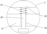
In the figure: 1. a box body; 2. an electrolyte tank; 3. a reciprocating screw rod; 4. a motor; 5. an electrode rod; 6. a slider; 7. a descaling box; 701. a sealing cover; 702. rotating the block; 703. a support; 704. rotating the rod; 705. a return spring; 8. a rotating frame; 9. a first electrode rod groove; 10. a second electrode bar slot; 11. a seal ring; 12. a filter box; 13. a piston cylinder; 14. a recovery pipe; 15. a first check valve; 16. a return pipe; 17. a second one-way valve; 18. a filter screen; 19. a piston; 20. a connecting pipe; 21. a first piston rod; 22. connecting grooves; 23. a second piston rod; 24. a first gear; 25. a first connecting rod; 26. a second gear; 27. a first drive pulley; 28. a guide groove; 29. a guide bar; 30. a first drive tooth; 31. a reversing wheel; 32. a second gear; 33. a second connecting rod; 34. a third gear; 35. a third gear; 36. a second transmission wheel; 37. a transmission belt; 38. grinding blocks; 39. a spring guide rod groove; 40. a spring guide rod; 41. a spring.
Detailed Description
The technical solutions in the embodiments of the present invention will be clearly and completely described below with reference to the drawings in the embodiments of the present invention, and it is obvious that the described embodiments are only a part of the embodiments of the present invention, and not all of the embodiments. All other embodiments, which can be derived by a person skilled in the art from the embodiments given herein without making any creative effort, shall fall within the protection scope of the present invention.
Referring to fig. 1-6, the present invention provides a technical solution: an electrode descaling device comprises a box body 1, an electrolyte tank 2, a reciprocating screw rod 3, a motor 4, an electrode rod 5, a sliding block 6, a descaling box 7, a rotating frame 8, a first electrode rod groove 9, a second electrode rod groove 10, a sealing ring 11, a filter box 12, a piston cylinder 13, a recycling pipe 14, a first check valve 15, a return pipe 16, a second check valve 17, a filter screen 18, a piston 19, a connecting pipe 20, a first piston rod 21, a connecting groove 22, a second piston rod 23, a first gear 24, a first connecting rod 25, a second gear 26, a first driving wheel 27, a guide groove 28, a guide rod 29, a first driving tooth 30, a reversing wheel 31, a second driving tooth 32, a second connecting rod 33, a third gear 34, a third driving tooth 35, a second driving wheel 36, a driving belt 37, a grinding block 38, a spring guide rod groove 39, a spring guide rod 40 and a spring 41, wherein the electrolyte tank 2 is arranged in the box body 1, the interior of the electrolyte tank 2 is rotatably connected with the opening close to the top end, the reciprocating screw rod 3 is arranged at the outer side of the box body 1, and the motor 4 is close to the end of the reciprocating screw rod 3,
the shaft end of the motor 4 is fixedly connected with the reciprocating screw rod 3, the inner wall of one side of the electrolyte tank 2 is provided with an electrode bar 5, the reciprocating screw rod 3 is connected with a sliding block 6 through screw threads, the bottom of the sliding block 6 is fixedly connected with a descaling box 7, a sealing cover 701 is rotatably connected to the outer side of the descaling box 7 close to the first electrode bar groove 9, a rotating block 702 is fixed at the top of the sealing cover 701, the two sides of the descaling box 7 close to the rotating block 702 are fixed with brackets 703, the rotating block 702 is rotatably connected with the brackets 703 through a rotating rod 704, a return spring 705 is sleeved on the rotating rod 704 between the rotating block 702 and the bracket 703, the rotating block 702 is elastically connected with the bracket 703 through a return spring 705, and one end of the return spring 705 is fixedly connected with the bracket 703, the inside of the descaling box 7 is rotatably connected with a rotating frame 8, a first electrode bar groove 9 penetrates through one side of the descaling box 7 close to the rotating frame 8, the other end of the return spring 705 is fixedly connected with the rotating block 702, when the electrode rod 5 penetrates the first electrode rod groove 9, the sealing cover 701 is pushed open by the electrode rod 5, so that the sealing cover 701 is rotated by the rotating rod 704, the return spring 705 is deformed, when the end of the electrode rod 5 enters the inside of the descaling box 7 for descaling, the return spring 705 can drive the sealing cover 701 to automatically seal the first electrode rod groove 9, so as to prevent scale blocks from flowing out of the inside of the descaling box 7 through the first electrode rod groove 9, a second electrode bar groove 10 penetrates through the other side of the descaling box 7 close to the rotating frame 8, sealing rings 11 are arranged on the inner sides of the first electrode bar groove 9 and the second electrode bar groove 10, a filter box 12 is arranged on the outer side of the box body 1, and a piston cylinder 13 is arranged above the box body 1 close to the filter box 12;
the bottom of the descaling box 7 is communicated with a recovery pipe 14, one end, far away from the descaling box 7, of the recovery pipe 14 is communicated with one side, close to the upper part, of the filter box 12, a first one-way valve 15 is installed inside one side, close to the descaling box 7, of the recovery pipe 14, the first one-way valve 15 is in one-way flow in the direction from the descaling box 7 to the filter box 12, one side of the bottom of the filter box 12 is communicated with the electrolyte tank 2 through a return pipe 16, a second one-way valve 17 is installed inside the return pipe 16, the second one-way valve 17 is in one-way flow in the direction from the filter box 12 to the box body 1, a filter screen 18 is installed in the middle of the inner side of the filter box 12, a piston 19 is arranged inside the piston cylinder 13, the end of the piston cylinder 13 is communicated with the top of the filter box 12 through a connecting pipe 20, and one side, close to the box body 1, of the piston 19 is fixedly connected with a first piston rod 21;
the first piston rod 21 extends to the inside of the electrolyte tank 2 through the piston cylinder 13 and the inside of the box body 1, one end of the first piston rod 21, which is far away from the piston 19, is provided with a connecting groove 22, one end of the second piston rod 23 is positioned inside the connecting groove 22, the piston 19 is made of rubber materials, the outer diameter of the piston 19 is equal to the inner diameter of the piston cylinder 13, when the motor 4 drives the descaling box 7 to move towards the electrode bar 5 through the reciprocating screw rod 3, the descaling box 7 drives the second piston rod 23 to move in the connecting groove 22, the electrode bar 5 is descaled through the descaling box 7, when the descaling box 7 moves to the position where the electrode rod 5 is close to the right side, the second piston rod 23 moves to the right end of the connecting groove 22, so that the second piston rod 23 drives the piston 19 to move to the right side through the first piston rod 21, a negative pressure state is formed in the filtering tank 12 through the connection pipe 20, the first check valve 15 is opened, the electrolyte mixed with the scale lump ground into fine particles enters the interior of the recovering pipe 14 through the first check valve 15, and then enters the interior of the filtering tank 12, after the scale blocks are filtered by the filter screen 18, the electrolyte flows to the bottom of the filter box 12, when the descaling box 7 moves towards the right side, the first one-way valve 15 is closed, the second one-way valve 17 is opened, so that the electrolyte enters the inside of the electrolyte tank 2 through the return pipe 16, when the descaling box 7 moves leftwards and rightwards to descale the electrode rod 5, the scale block is processed, one end of the second piston rod 23 far away from the first piston rod 21 is fixedly connected with the descaling box 7, a first gear 24 is fixed at the middle part of the outer side of the rotating frame 8, a first connecting rod 25 is rotatably connected above the descaling box 7 close to the first gear 24, a second gear 26 is fixed at one end of the first connecting rod 25 close to the first gear 24;
the second gear 26 is meshed with the first gear 24, one end of the first connecting rod 25, which is close to the outer side of the descaling box 7, is fixedly connected with a first driving wheel 27, a guide groove 28 penetrates through the lower part of the sliding block 6, which is close to the reciprocating screw rod 3, a guide rod 29 penetrates through the inner part of the guide groove 28, two ends of the guide rod 29 are fixedly connected with the inner wall of the electrolyte tank 2, first driving teeth 30 are fixed at the bottom of the guide rod 29 at equal intervals, a reversing wheel 31 is rotatably connected with the inner part of the sliding block 6, which is close to the lower part of the guide rod 29, the reversing wheel 31 is meshed with the first driving teeth 30 through second driving teeth 32, and one side of the sliding block 6, which is close to the reversing wheel 31, is rotatably connected with a second connecting rod 33;
a third gear 34 is fixed on one side of the second connecting rod 33 close to the reversing wheel 31, the reversing wheel 31 is engaged with the third gear 34 through a third transmission gear 35, a second transmission wheel 36 is fixed on one end of the second connecting rod 33 far away from the third gear 34, a transmission belt 37 is sleeved on the first transmission wheel 27 and the second transmission wheel 36, grinding blocks 38 are symmetrically arranged inside the rotating frame 8, the electrode bar 5 is exactly aligned with the first electrode bar groove 9 and the second electrode bar groove 10, the outer diameter of the electrode bar 5 is equal to the inner diameter of the sealing ring 11, when the electrode bar 5 penetrates through the interiors of the first electrode bar groove 9 and the second electrode bar groove 10, and the surface of the electrode bar 5 is ground and descaled through the grinding blocks 38, the sealing ring 11 is used for sealing the connection between the electrode bar 5 and the first electrode bar groove 9 and the second electrode bar groove 10, the polished scale block is prevented from flowing out of the descaling box 7 through the first electrode bar groove 9 and the second electrode bar groove 10, the transmission belt 37 is meshed with the first transmission wheel 27 and the second transmission wheel 36, the first transmission wheel 27 and the second transmission wheel 36 form a transmission structure through the transmission belt 37, when the reciprocating screw rod 3 drives the sliding block 6 to move, the guide rod 29 moves in the guide groove 28, the guide rod 29 drives the reversing wheel 31 to rotate through the meshing of the first transmission tooth 30 and the second transmission tooth 32, the reversing wheel 31 drives the second connecting rod 33 to rotate through the meshing of the third gear 34 and the third gear 34, the second connecting rod 33 drives the second transmission wheel 36 to rotate, the second transmission wheel 36 drives the first transmission wheel 27 to rotate through the transmission belt 37, the first transmission wheel 27 drives the second gear 26 to rotate through the first connecting rod 25, the second gear 26 drives the rotating frame 8 to rotate through the meshing with the first gear 24, the rotating frame 8 is enabled to drive the grinding block 38 to rotate, when the filter box 12 moves, the grinding block 38 is driven to rotate to grind and remove scale on the electrode rod 5, spring guide rod grooves 39 are symmetrically formed in the middle of the rotating frame 8, which is close to the grinding block 38, a spring guide rod 40 is fixed on one side of the grinding block 38, which is close to the spring guide rod grooves 39, a spring 41 is sleeved on the spring guide rod 40 between the grinding block 38 and the spring guide rod grooves 39, the grinding block 38 is elastically connected with the rotating frame 8 through the spring 41, one side, which is far away from the spring 41, of the grinding block 38 is a concave surface, the radian of the concave surface of the grinding block 38 is equal to the surface radian of the electrode rod 5, when the electrode rod 5 is ground and removed scale through the grinding block 38, the contact area between the concave surface of the grinding block 38 and the electrode rod 5 can be increased, and scale removal of the electrode rod 5 is facilitated.
The working principle is as follows: when the electrode descaling device is used, firstly, the motor 4 drives the sliding block 6 to move towards the right through the reciprocating screw rod 3, so that the sliding block 6 drives the descaling box 7 to move towards the right, so that the electrode rods 5 enter the inside of the descaling box 7, when the sliding block 6 moves, the guide rod 29 moves in the guide groove 28, so that the guide rod 29 drives the reversing wheel 31 to rotate through the meshing of the first transmission teeth 30 and the second transmission teeth 32, the reversing wheel 31 drives the second connecting rod 33 to rotate through the meshing of the third gear 34 and the third gear 34, the second connecting rod 33 drives the second transmission wheel 36 to rotate, the second transmission wheel 36 drives the first transmission wheel 27 to rotate through the transmission belt 37, the first transmission wheel 27 drives the second gear 26 to rotate through the first connecting rod 25, so that the second gear 26 drives the rotating frame 8 to rotate through the meshing of the descaling first gear 24, the rotating frame 8 drives the grinding block 38 to rotate, so that when the filter box 12 moves, the grinding block 38 is driven to rotate to grind the electrode rods 5, and drive the descaling box 7 to move back and forth through the reciprocating screw rod 3 to polish the electrode rods 5;
when the motor 4 drives the descaling box 7 to move towards the direction of the electrode rod 5 through the reciprocating screw rod 3, the descaling box 7 drives the second piston rod 23 to move in the connecting groove 22, the electrode rod 5 is descaled through the descaling box 7, when the descaling box 7 moves to the position, close to the right side, of the electrode rod 5, the second piston rod 23 moves to the right end of the connecting groove 22, the second piston rod 23 drives the piston 19 to move towards the right side through the first piston rod 21, a negative pressure state is formed in the filter box 12 through the connecting pipe 20, the first check valve 15 is opened, electrolyte mixed with the fine particles and grinded scale blocks enter the interior of the recovery pipe 14 through the first check valve 15 and then enter the interior of the filter box 12, after the scale blocks are filtered through the filter screen 18, the electrolyte flows to the bottom of the filter box 12, when the descaling box 7 moves towards the right side, the first check valve 15 is closed, the second check valve 17 is opened, the electrolyte enters the interior of the electrolyte tank 2 through the electrolyte 16, and the descaling box 7 is convenient to treat the scale blocks when the electrode rod 5 moves left and right in the descaling box 7 to move.
Although the present invention has been described in detail with reference to the foregoing embodiments, it will be apparent to those skilled in the art that modifications may be made to the embodiments described in the foregoing embodiments, or equivalents may be substituted for elements thereof.
Claims (9)
1. The utility model provides an electrode scale removal device, includes box (1) and second piston rod (23), its characterized in that: an electrolyte tank (2) is arranged in the box body (1), a reciprocating screw rod (3) is rotatably connected in the electrolyte tank (2) close to the opening at the top end, a motor (4) is arranged on the outer side of the box body (1) close to the end part of the reciprocating screw rod (3), wherein,
the device comprises a motor (4), a reciprocating screw rod (3), an electrode rod (5) is installed on the inner wall of one side of an electrolyte tank (2), a sliding block (6) is connected to the reciprocating screw rod (3) in a threaded manner, a descaling box (7) is fixedly connected to the bottom of the sliding block (6), a rotating frame (8) is rotatably connected to the inside of the descaling box (7), a first electrode rod groove (9) penetrates through one side, close to the rotating frame (8), of the descaling box (7), a second electrode rod groove (10) penetrates through the other side, close to the rotating frame (8), of the descaling box (7), sealing rings (11) are installed on the inner sides of the first electrode rod groove (9) and the second electrode rod groove (10), a filter box (12) is installed on the outer side of the box body (1), and a piston cylinder (13) is installed above the box (1), close to the filter box (12);
the bottom of the descaling box (7) is communicated with a recovery pipe (14), one end, far away from the descaling box (7), of the recovery pipe (14) is communicated with one side, close to the upper part, of the filtering box (12), a first one-way valve (15) is installed inside one side, close to the descaling box (7), of the recovery pipe (14), one side of the bottom of the filtering box (12) is communicated with the electrolytic solution tank (2) through a return pipe (16), a second one-way valve (17) is installed inside the return pipe (16), a filtering net (18) is installed in the middle of the inner side of the filtering box (12), a piston (19) is arranged inside the piston cylinder (13), the end part of the piston cylinder (13) is communicated with the top of the filtering box (12) through a connecting pipe (20), and one side, close to the box body (1), of the piston (19) is fixedly connected with a first piston rod (21);
the first piston rod (21) penetrates through the piston cylinder (13) and the inside of the box body (1) and extends to the inside of the electrolyte tank (2), a connecting groove (22) is formed in one end, far away from the piston (19), of the first piston rod (21), one end of the second piston rod (23) is located inside the connecting groove (22), one end, far away from the first piston rod (21), of the second piston rod (23) is fixedly connected with the descaling box (7), a first gear (24) is fixed in the middle of the outer side of the rotating frame (8), a first connecting rod (25) is rotatably connected above the descaling box (7) close to the first gear (24), and a second gear (26) is fixed at one end, close to the first gear (24), of the first connecting rod (25);
the second gear (26) is meshed with the first gear (24), one end, close to the outer side of the descaling box (7), of the first connecting rod (25) is fixedly connected with a first transmission wheel (27), a guide groove (28) penetrates through the lower portion, close to the reciprocating screw rod (3), of the sliding block (6), a guide rod (29) penetrates through the guide groove (28), two ends of the guide rod (29) are fixedly connected with the inner wall of the electrolytic bath (2), first transmission teeth (30) are fixed to the bottom of the guide rod (29) at equal intervals, a reversing wheel (31) is rotatably connected to the inner portion, close to the lower portion of the guide rod (29), of the sliding block (6), the reversing wheel (31) is meshed with the first transmission teeth (30) through second transmission teeth (32), and a second connecting rod (33) is rotatably connected to one side, close to the reversing wheel (31), of the sliding block (6);
one side that second connecting rod (33) is close to reverse wheel (31) is fixed with third gear (34), reverse wheel (31) meshes with third gear (34) mutually through third driving tooth (35), the one end that third gear (34) were kept away from in second connecting rod (33) is fixed with second drive wheel (36), cover on first drive wheel (27) and second drive wheel (36) has drive belt (37), the inside symmetry of rotating turret (8) is provided with sanding block (38), spring guide bar groove (39) have been seted up to the middle part symmetry that rotating turret (8) are close to sanding block (38), one side that sanding block (38) are close to spring guide bar groove (39) is fixed with spring guide (40), the cover has spring (41) on spring guide bar (40) between sanding block (38) to spring guide bar groove (39).
2. An electrode descaling device according to claim 1, wherein: the electrode bar (5) is exactly aligned with the first electrode bar groove (9) and the second electrode bar groove (10), and the outer diameter of the electrode bar (5) is equal to the inner diameter of the sealing ring (11).
3. An electrode descaling device according to claim 1, wherein: descaling case (7) are including sealed lid (701), turning block (702), support (703), dwang (704) and reset spring (705), the outside that descaling case (7) are close to first electrode stick groove (9) is rotated and is connected with sealed lid (701), the top of sealed lid (701) is fixed with turning block (702), the both sides that descaling case (7) are close to turning block (702) are fixed with support (703), turning block (702) rotate with support (703) through dwang (704) and are connected, the cover has reset spring (705) to dwang (704) between support (703) on turning block (702).
4. An electrode descaling device according to claim 3, wherein: the rotating block (702) is elastically connected with the support (703) through a return spring (705), one end of the return spring (705) is fixedly connected with the support (703), and the other end of the return spring (705) is fixedly connected with the rotating block (702).
5. An electrode descaling device according to claim 1, wherein: the first one-way valve (15) is communicated in one way from the descaling box (7) to the filter box (12).
6. An electrode descaling device according to claim 1, wherein: the second one-way valve (17) is communicated in a one-way mode from the filter box (12) to the box body (1).
7. An electrode descaling device according to claim 1, wherein: the piston (19) is made of rubber materials, and the outer diameter of the piston (19) is equal to the inner diameter of the piston cylinder (13).
8. An electrode descaling device according to claim 1, wherein: the transmission belt (37) is meshed with the first transmission wheel (27) and the second transmission wheel (36), and the first transmission wheel (27) and the second transmission wheel (36) form a transmission structure through the transmission belt (37).
9. An electrode descaling device according to claim 1, wherein: the polishing block (38) is elastically connected with the rotating frame (8) through the spring (41), one side, far away from the spring (41), of the polishing block (38) is a concave surface, and the radian of the concave surface of the polishing block (38) is equal to that of the surface of the electrode rod (5).
Priority Applications (1)
| Application Number | Priority Date | Filing Date | Title |
|---|---|---|---|
| CN202011032196.4A CN112139615B (en) | 2020-09-27 | 2020-09-27 | Electrode descaling device |
Applications Claiming Priority (1)
| Application Number | Priority Date | Filing Date | Title |
|---|---|---|---|
| CN202011032196.4A CN112139615B (en) | 2020-09-27 | 2020-09-27 | Electrode descaling device |
Publications (2)
| Publication Number | Publication Date |
|---|---|
| CN112139615A CN112139615A (en) | 2020-12-29 |
| CN112139615B true CN112139615B (en) | 2022-12-06 |
Family
ID=73894287
Family Applications (1)
| Application Number | Title | Priority Date | Filing Date |
|---|---|---|---|
| CN202011032196.4A Active CN112139615B (en) | 2020-09-27 | 2020-09-27 | Electrode descaling device |
Country Status (1)
| Country | Link |
|---|---|
| CN (1) | CN112139615B (en) |
Families Citing this family (2)
| Publication number | Priority date | Publication date | Assignee | Title |
|---|---|---|---|---|
| CN115594336A (en) * | 2022-09-29 | 2023-01-13 | 陕西延长中煤榆林能源化工有限公司(Cn) | Circulating cooling water descaling device and use method thereof |
| CN116425269B (en) * | 2023-04-18 | 2023-12-19 | 青海九零六工程勘察设计院有限责任公司 | Geothermal water recharging, filtering and purifying treatment equipment |
Citations (5)
| Publication number | Priority date | Publication date | Assignee | Title |
|---|---|---|---|---|
| US5630749A (en) * | 1994-09-01 | 1997-05-20 | Koch; Walter | Apparatus for the mechanical removal of deposits on welding electrodes |
| CN207447512U (en) * | 2017-10-23 | 2018-06-05 | 上海法信机电设备制造有限公司 | Electrode slug collection device and electrode dressing system |
| CN208004934U (en) * | 2018-03-15 | 2018-10-26 | 东莞市远诚数控科技有限公司 | One kind removing device for removing oxide layer |
| CN208391720U (en) * | 2018-05-15 | 2019-01-18 | 褚雯 | A kind of plastic products outer surface polishing burr remover |
| CN211540629U (en) * | 2019-11-26 | 2020-09-22 | 苏州泰航精密冲压有限公司 | Deburring device capable of adjusting polishing degree |
-
2020
- 2020-09-27 CN CN202011032196.4A patent/CN112139615B/en active Active
Patent Citations (5)
| Publication number | Priority date | Publication date | Assignee | Title |
|---|---|---|---|---|
| US5630749A (en) * | 1994-09-01 | 1997-05-20 | Koch; Walter | Apparatus for the mechanical removal of deposits on welding electrodes |
| CN207447512U (en) * | 2017-10-23 | 2018-06-05 | 上海法信机电设备制造有限公司 | Electrode slug collection device and electrode dressing system |
| CN208004934U (en) * | 2018-03-15 | 2018-10-26 | 东莞市远诚数控科技有限公司 | One kind removing device for removing oxide layer |
| CN208391720U (en) * | 2018-05-15 | 2019-01-18 | 褚雯 | A kind of plastic products outer surface polishing burr remover |
| CN211540629U (en) * | 2019-11-26 | 2020-09-22 | 苏州泰航精密冲压有限公司 | Deburring device capable of adjusting polishing degree |
Also Published As
| Publication number | Publication date |
|---|---|
| CN112139615A (en) | 2020-12-29 |
Similar Documents
| Publication | Publication Date | Title |
|---|---|---|
| CN112139615B (en) | Electrode descaling device | |
| CN211659440U (en) | Sewage recovery device with automatic impurity separation function | |
| CN115780056B (en) | Preparation method of superfine cerium dioxide nano material | |
| CN216778137U (en) | A filter equipment for sewage recovery of circulating water | |
| CN215403767U (en) | High-efficient dewatering device is taked care of to mud | |
| CN112811648B (en) | Sewage filtering and recycling device | |
| CN213407981U (en) | Water purification device for rapidly treating factory discharged wastewater | |
| CN211659461U (en) | Grinding machine filters device of grinding oil | |
| CN217773394U (en) | Coating filtration equipment with function of discharging filter residues | |
| CN218516220U (en) | Inlet water deslagging device of sewage treatment plant | |
| CN208809896U (en) | A kind of aqueous polyurethane gloves slurry production mixing arrangement convenient for discharging | |
| CN212864377U (en) | Industrial waste water recovery treatment clarification plant | |
| CN212700896U (en) | Microporous filter | |
| CN212610009U (en) | Water pollution collection device | |
| CN214268407U (en) | Stainless steel water tank with heavy metal separation structure for water treatment | |
| CN214031811U (en) | Industrial sewage advanced treatment device | |
| CN217265106U (en) | Full-automatic water purifier for sewage treatment | |
| CN110589912A (en) | Sewage debris collection processing apparatus | |
| CN218778823U (en) | Grinding fluid regeneration recovery unit | |
| CN218501427U (en) | Textile machine waste liquid treatment device | |
| CN218801238U (en) | Metal product polishing device convenient for chip removal | |
| CN217312151U (en) | Anodic oxidation line waste water recovery device | |
| CN217909386U (en) | Sewage treatment equipment convenient to clean | |
| CN215654205U (en) | Flocculate salvaging device for extraction process | |
| CN213103544U (en) | Artificial diamond micro powder cleaning and collecting device |
Legal Events
| Date | Code | Title | Description |
|---|---|---|---|
| PB01 | Publication | ||
| PB01 | Publication | ||
| SE01 | Entry into force of request for substantive examination | ||
| SE01 | Entry into force of request for substantive examination | ||
| TA01 | Transfer of patent application right |
Effective date of registration: 20221111 Address after: No.15, Changhong Road, Xiangyang City, Hubei Province 441000 Applicant after: XIANGYANG POWER SUPPLY COMPANY OF STATE GRID HUBEI ELECTRIC POWER Co.,Ltd. Applicant after: State Grid Hubei Comprehensive Energy Service Co.,Ltd. Xiangyang Branch Address before: 056002 Huasheng Industrial Park, No.9 Xinxing Road, Handan Economic Development Zone, Congtai District, Handan City, Hebei Province Applicant before: Jia Zhangmin |
|
| TA01 | Transfer of patent application right | ||
| GR01 | Patent grant | ||
| GR01 | Patent grant |