CN112139606A - Deburring machine for manufacturing hardware fittings - Google Patents
Deburring machine for manufacturing hardware fittings Download PDFInfo
- Publication number
- CN112139606A CN112139606A CN201910580831.3A CN201910580831A CN112139606A CN 112139606 A CN112139606 A CN 112139606A CN 201910580831 A CN201910580831 A CN 201910580831A CN 112139606 A CN112139606 A CN 112139606A
- Authority
- CN
- China
- Prior art keywords
- support frame
- motor
- adjusting nut
- lead screw
- working platform
- Prior art date
- Legal status (The legal status is an assumption and is not a legal conclusion. Google has not performed a legal analysis and makes no representation as to the accuracy of the status listed.)
- Withdrawn
Links
Images


Classifications
-
- B—PERFORMING OPERATIONS; TRANSPORTING
- B23—MACHINE TOOLS; METAL-WORKING NOT OTHERWISE PROVIDED FOR
- B23D—PLANING; SLOTTING; SHEARING; BROACHING; SAWING; FILING; SCRAPING; LIKE OPERATIONS FOR WORKING METAL BY REMOVING MATERIAL, NOT OTHERWISE PROVIDED FOR
- B23D79/00—Methods, machines, or devices not covered elsewhere, for working metal by removal of material
- B23D79/02—Machines or devices for scraping
- B23D79/04—Machines or devices for scraping with rotating cutting-tool, e.g. for smoothing linings of bearings
-
- B—PERFORMING OPERATIONS; TRANSPORTING
- B23—MACHINE TOOLS; METAL-WORKING NOT OTHERWISE PROVIDED FOR
- B23Q—DETAILS, COMPONENTS, OR ACCESSORIES FOR MACHINE TOOLS, e.g. ARRANGEMENTS FOR COPYING OR CONTROLLING; MACHINE TOOLS IN GENERAL CHARACTERISED BY THE CONSTRUCTION OF PARTICULAR DETAILS OR COMPONENTS; COMBINATIONS OR ASSOCIATIONS OF METAL-WORKING MACHINES, NOT DIRECTED TO A PARTICULAR RESULT
- B23Q1/00—Members which are comprised in the general build-up of a form of machine, particularly relatively large fixed members
- B23Q1/25—Movable or adjustable work or tool supports
- B23Q1/26—Movable or adjustable work or tool supports characterised by constructional features relating to the co-operation of relatively movable members; Means for preventing relative movement of such members
-
- B—PERFORMING OPERATIONS; TRANSPORTING
- B23—MACHINE TOOLS; METAL-WORKING NOT OTHERWISE PROVIDED FOR
- B23Q—DETAILS, COMPONENTS, OR ACCESSORIES FOR MACHINE TOOLS, e.g. ARRANGEMENTS FOR COPYING OR CONTROLLING; MACHINE TOOLS IN GENERAL CHARACTERISED BY THE CONSTRUCTION OF PARTICULAR DETAILS OR COMPONENTS; COMBINATIONS OR ASSOCIATIONS OF METAL-WORKING MACHINES, NOT DIRECTED TO A PARTICULAR RESULT
- B23Q11/00—Accessories fitted to machine tools for keeping tools or parts of the machine in good working condition or for cooling work; Safety devices specially combined with or arranged in, or specially adapted for use in connection with, machine tools
- B23Q11/0042—Devices for removing chips
- B23Q11/0046—Devices for removing chips by sucking
-
- B—PERFORMING OPERATIONS; TRANSPORTING
- B23—MACHINE TOOLS; METAL-WORKING NOT OTHERWISE PROVIDED FOR
- B23Q—DETAILS, COMPONENTS, OR ACCESSORIES FOR MACHINE TOOLS, e.g. ARRANGEMENTS FOR COPYING OR CONTROLLING; MACHINE TOOLS IN GENERAL CHARACTERISED BY THE CONSTRUCTION OF PARTICULAR DETAILS OR COMPONENTS; COMBINATIONS OR ASSOCIATIONS OF METAL-WORKING MACHINES, NOT DIRECTED TO A PARTICULAR RESULT
- B23Q3/00—Devices holding, supporting, or positioning work or tools, of a kind normally removable from the machine
- B23Q3/02—Devices holding, supporting, or positioning work or tools, of a kind normally removable from the machine for mounting on a work-table, tool-slide, or analogous part
- B23Q3/06—Work-clamping means
Landscapes
- Engineering & Computer Science (AREA)
- Mechanical Engineering (AREA)
- Physics & Mathematics (AREA)
- Optics & Photonics (AREA)
- Grinding And Polishing Of Tertiary Curved Surfaces And Surfaces With Complex Shapes (AREA)
Abstract
The invention discloses a deburring machine for manufacturing hardware accessories, which comprises a working platform, a transmission mechanism and a controller, wherein grooves are formed in two sides of the top end of the working platform, a clamping mechanism is arranged inside each groove, a scrap collecting groove is movably arranged inside the working platform, strip-shaped through holes are uniformly formed in the working platform at the top end of the scrap collecting groove, a U-shaped support frame is arranged at the top end of the working platform, the transmission mechanism is arranged at the top end of the U-shaped support frame, the transmission mechanism comprises a first screw rod, a sliding block, a first adjusting nut, an adjusting groove, an air cylinder, a first motor and an electric telescopic rod, a second motor and a deburring scraper are installed at the bottom end of the air cylinder, a dust removal mechanism is arranged on one side of the U-shaped support frame, and the controller is installed on one side of the. The invention can extract metal dust generated in the deburring process, is convenient for adjusting the position of the deburring scraper and fixing hardware fittings.
Description
Technical Field
The invention relates to the technical field of hardware fitting manufacturing equipment, in particular to a deburring machine for hardware fitting manufacturing.
Background
Machine parts or components manufactured by hardware and small hardware products are called hardware fittings, the machine parts or the components can be used independently or can be used as auxiliary tools, after the hardware fittings are processed, burrs are generated on the surfaces or local parts, if the burrs are not removed, a plurality of unnecessary troubles are caused, the use effect of the hardware fittings is easily influenced, mechanical equipment is easily damaged, and therefore a deburring machine is needed to remove the burrs on the surfaces of the hardware fittings;
the existing deburring machine generally has the following problems:
(1) at present, when a traditional deburring machine for hardware accessories works, metal dust is easily generated, and the metal dust is easy to cause environmental pollution due to dispersion and is inhaled by a human body, so that respiratory diseases can be caused, and a plurality of inconvenient places are brought to people;
(2) because the types of hardware fittings are rich and the shapes of the hardware fittings are different, the position of a deburring scraper cannot be adjusted according to the shapes of the hardware fittings by the conventional deburring machine, and the applicability is not strong;
(3) before the burring, need fix hardware fitting earlier, the hardware fitting of the degree of being inconvenient different grade type is fixed to current burr-grinding machine.
Disclosure of Invention
The invention aims to provide a deburring machine for manufacturing hardware fittings, which aims to solve the problems that metal dust is generated to pollute the environment, the position of a deburring scraper is inconvenient to adjust and different types of hardware fittings are inconvenient to fix in the background technology.
In order to achieve the purpose, the invention provides the following technical scheme: a deburring machine for manufacturing hardware accessories comprises a working platform, a transmission mechanism and a controller, wherein supporting legs are mounted at four corners of the bottom end of the working platform, grooves are formed in two sides of the top end of the working platform, a clamping mechanism is arranged inside each groove and comprises a second lead screw, a clamping plate, a roller, a second adjusting nut, a belt and a hand wheel, a scrap collecting groove is movably arranged inside the working platform through a sliding rail, strip-shaped through holes are uniformly formed in the working platform at the top end of the scrap collecting groove, a U-shaped support frame is arranged at the top end of the working platform, the transmission mechanism is arranged at the top end of the U-shaped support frame and comprises a first lead screw, a sliding block, a first adjusting nut, an adjusting groove, an air cylinder, a first motor and an electric telescopic rod, a second motor is mounted at the bottom end of the air cylinder, and a deburring scraper is mounted at the output end of, one side of U type support frame is provided with dust removal mechanism, and dust removal mechanism includes water tank and air pump, the controller is installed to one side of U type support frame, and the output of controller passes through the wire electricity with the input of air pump, cylinder, first motor, electric telescopic handle and second motor and is connected.
Preferably, the air pump is fixed on one side of the inside of the U-shaped support frame through a bolt, and the other side of the U-shaped support frame is provided with a water tank through a support plate.
Preferably, the input of air pump is provided with the dust screen, the output of air pump is provided with the pipe, and the pipe extends to below the inside liquid level of water tank, the top at water tank both ends evenly is provided with the ventilation hole.
Preferably, first motor is fixed in one side of U type support frame, and the inboard that the output of first motor extends to U type support frame is provided with first lead screw, the screw thread is provided with first adjusting nut on the first lead screw, and first adjusting nut's bottom installs the adjustment tank, the inside one end of adjustment tank is provided with electric telescopic handle, and electric telescopic handle's output is provided with the slider, the cylinder is installed to the bottom of slider.
Preferably, the two sides of the top end of the first adjusting nut are connected with the bottom end of the U-shaped supporting frame in a sliding mode through sliding rails, and the two sides of the sliding block are connected with the inner side wall of the adjusting groove in a sliding mode through sliding rails.
Preferably, the second lead screw is installed in the groove through a bearing, one end of the second lead screw extends to one side of the working platform and is provided with a roller, the roller is connected through a belt, a hand wheel is arranged on the second lead screw on one side of the working platform, second adjusting nuts are arranged on two sides of the second lead screw, and clamping plates are arranged on the top ends of the second adjusting nuts.
Preferably, the second screw rod is provided with external threads, the threads on two sides of the second screw rod are opposite, and the second screw rod is in threaded connection with the second adjusting nut.
Compared with the prior art, the invention has the beneficial effects that: the hardware fitting manufacture deburring machine
(1) An air pump and a water tank are respectively arranged on the inner side and the outer side of the U-shaped support frame, a guide pipe is arranged at the output end of the air pump and extends to a position below the liquid level in the water tank, and metal dust generated in the deburring process is pumped into the water tank through the air pump, so that the environmental pollution is reduced;
(2) according to the deburring machine for manufacturing the hardware accessories, the first lead screw and the first motor are arranged at the top end inside the U-shaped support frame, the first adjusting nut is arranged on the first lead screw through threads, the first lead screw is driven to rotate through the first motor, the position of the first adjusting nut on the first lead screw can be adjusted, the bottom end of the first adjusting nut is provided with an adjusting groove, a sliding block is arranged inside the adjusting groove through an electric telescopic rod, the position of the sliding block inside the adjusting groove is adjusted through the expansion and contraction of the electric telescopic rod, the air cylinder is arranged at the bottom end of the sliding block, the position of a deburring scraper can be adjusted from three directions, burrs on the surfaces of the hardware accessories of different types can be conveniently removed, and the deburring;
(3) this deburring machine is used in hardware fitting manufacturing all is provided with the recess through the both sides on work platform top, and the inside of recess all installs the second lead screw, the one end of second lead screw is provided with gyro wheel and hand wheel, the gyro wheel passes through the belt and connects, the both sides of second lead screw all are provided with second adjusting nut through the screw thread, rotatory hand wheel, the second lead screw that drives both sides rotates simultaneously, and the external screw thread of second lead screw both sides is opposite, thereby can drive second adjusting nut and splint and draw close to the centre, be convenient for fix the hardware fitting of different shapes.
Drawings
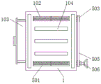
FIG. 1 is a schematic cross-sectional front view of the present invention;
FIG. 2 is a schematic top view of the working platform of the present invention;
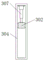
FIG. 3 is a schematic bottom view of the adjusting groove of the present invention;
FIG. 4 is a schematic side view of the working platform of the present invention;
FIG. 5 is an enlarged view of the structure at A in FIG. 1 according to the present invention;
FIG. 6 is a block diagram of the system of the present invention.
In the figure: 1. a working platform; 101. a U-shaped support frame; 102. a groove; 103. a debris collecting groove; 104. a strip-shaped through hole; 2. a dust removal mechanism; 201. a water tank; 202. an air pump; 3. a transmission mechanism; 301. a first lead screw; 302. a slider; 303. a first adjusting nut; 304. an adjustment groove; 305. a cylinder; 306. a first motor; 307. an electric telescopic rod; 4. a controller; 5. a clamping mechanism; 501. a second lead screw; 502. a splint; 503. a roller; 504. a second adjusting nut; 505. a belt; 506. a hand wheel; 6. supporting legs; 7. a second motor; 8. and a deburring scraper.
Detailed Description
The technical solutions in the embodiments of the present invention will be clearly and completely described below with reference to the drawings in the embodiments of the present invention, and it is obvious that the described embodiments are only a part of the embodiments of the present invention, and not all of the embodiments. All other embodiments, which can be derived by a person skilled in the art from the embodiments given herein without making any creative effort, shall fall within the protection scope of the present invention.
Referring to fig. 1-6, an embodiment of the present invention is shown: a deburring machine for manufacturing hardware accessories comprises a working platform 1, a transmission mechanism 3 and a controller 4, supporting legs 6 are mounted at four corners of the bottom end of the working platform 1, grooves 102 are formed in two sides of the top end of the working platform 1, a clamping mechanism 5 is arranged inside each groove 102, each clamping mechanism 5 comprises a second lead screw 501, a clamping plate 502, a roller 503, a second adjusting nut 504, a belt 505 and a hand wheel 506, each second lead screw 501 is mounted inside each groove 102 through a bearing, one end of each second lead screw 501 extends to one side of the working platform 1 and is provided with the roller 503, the rollers 503 are connected through the belts 505, the hand wheel 506 is arranged on the second lead screw 501 on one side of the working platform 1, the second adjusting nuts 504 are arranged on two sides of the second lead screws 501, the clamping plates 502 are arranged at the top ends of the second adjusting nuts 504, and different types of hardware accessories can be fixed conveniently, the applicability is strong;
the second screw rod 501 is provided with external threads, the threads on two sides of the second screw rod 501 are opposite, the second screw rod 501 is in threaded connection with the second adjusting nut 504, and the second adjusting nut 504 on two sides of the second screw rod 501 can be driven to move relatively through the rotation of the second screw rod 501, so that the hardware fitting can be clamped conveniently;
the chip collecting groove 103 is movably arranged in the working platform 1 through a sliding rail, the working platform 1 at the top end of the chip collecting groove 103 is uniformly provided with strip-shaped through holes 104, the top end of the working platform 1 is provided with a U-shaped support frame 101, the top end of the U-shaped support frame 101 is provided with a transmission mechanism 3, the transmission mechanism 3 comprises a first screw rod 301, a sliding block 302, a first adjusting nut 303, an adjusting groove 304, a cylinder 305, a first motor 306 and an electric telescopic rod 307, the model of the cylinder 305 can be SC63, the model of the first motor 306 can be RJ090-E03520, the model of the electric telescopic rod 307 can be XC758, the bottom end of the cylinder 305 is provided with a second motor 7, the model of the second motor 7 can be Y160M1-2, the output end of the second motor 7 is provided with a deburring scraper 8, the first motor 306 is fixed on one side of the U-shaped support frame 101, and the output end of the first motor 306 extends to the, a first adjusting nut 303 is arranged on the first screw 301 in a threaded manner, an adjusting groove 304 is formed in the bottom end of the first adjusting nut 303, an electric telescopic rod 307 is arranged at one end inside the adjusting groove 304, a sliding block 302 is arranged at the output end of the electric telescopic rod 307, and an air cylinder 305 is arranged at the bottom end of the sliding block 302, so that the position of the deburring scraper 8 can be adjusted from three directions, and burrs on the surfaces of hardware fittings of different types can be removed;
the two sides of the top end of the first adjusting nut 303 are slidably connected with the bottom end of the U-shaped supporting frame 101 through sliding rails, the first adjusting nut 303 can stably slide at the bottom end of the U-shaped supporting frame 101, the two sides of the sliding block 302 are slidably connected with the inner side wall of the adjusting groove 304 through sliding rails, and the sliding block 302 can stably slide in the adjusting groove 304;
the dust removal mechanism 2 is arranged on one side of the U-shaped support frame 101, the dust removal mechanism 2 comprises a water tank 201 and an air pump 202, the model of the air pump 202 can be JY-024, the air pump 202 is fixed on one side of the inside of the U-shaped support frame 101 through bolts, the water tank 201 is arranged on the other side of the U-shaped support frame 101 through a support plate, metal dust generated in the deburring process can be pumped into the water tank 201, and environmental pollution is reduced;
the input end of the air pump 202 is provided with a dust screen, the output end of the air pump 202 is provided with a guide pipe, the guide pipe extends to a position below the liquid level in the water tank 201, the tops of the two ends of the water tank 201 are uniformly provided with vent holes, dust is dissolved in water, and gas is discharged to the outside through the vent holes;
the controller 4 is installed on one side of the U-shaped support frame 101, the type of the controller 4 can be FHR-211, and the output end of the controller 4 is electrically connected with the input ends of the air pump 202, the air cylinder 305, the first motor 306, the electric telescopic rod 307 and the second motor 7 through conducting wires.
The working principle is as follows: when the device is used, a power supply is switched on, a hardware fitting to be processed is placed in the middle of the working platform 1, the hand wheel 506 is rotated, the second screw rods 501 on two sides are driven to rotate simultaneously through the rollers 503 and the belt 505, threads on two sides of the second screw rods 501 are opposite, so that the clamping plates 502 and the second adjusting nuts 504 on two ends of the second screw rods 501 are driven to approach to the middle, the hardware fitting is fixed, then the switch of the first motor 306 is turned on through the controller 4, the first motor 306 drives the first screw rods 301 to rotate, the position of the first adjusting nuts 303 on the first screw rods 301 can be adjusted, then the switch of the electric telescopic rod 307 is turned on through the controller 4, the sliding block 302 is driven to slide in the adjusting groove 304 through the extension and retraction of the electric telescopic rod 307, the switch of the air cylinder 305 is turned on through the controller 4, and the heights of the second motor 7 and the deburring scraper 8 are adjusted, open the switch of second motor 7 and air pump 202 through controller 4, second motor 7 drives burring scraper 8 rotatory, thereby can carry out the burring to the hardware fitting of difference, perhaps burring to the different positions of hardware fitting, the suitability is strong, extract the inside to water tank 201 with the dust that the burring in-process produced through air pump 202, reduce environmental pollution, the piece that falls on work platform 1 in the burring in-process, get into the inside in collection piece groove 103 through bar-shaped through-hole 104, it can clear up it to take out collection piece groove 103.
It will be evident to those skilled in the art that the invention is not limited to the details of the foregoing illustrative embodiments, and that the present invention may be embodied in other specific forms without departing from the spirit or essential attributes thereof. The present embodiments are therefore to be considered in all respects as illustrative and not restrictive, the scope of the invention being indicated by the appended claims rather than by the foregoing description, and all changes which come within the meaning and range of equivalency of the claims are therefore intended to be embraced therein. Any reference sign in a claim should not be construed as limiting the claim concerned.
Claims (7)
1. The utility model provides a deburring machine is used in hardware fitting manufacturing, includes work platform (1), drive mechanism (3) and controller (4), its characterized in that: supporting legs (6) are all installed to four corners of work platform (1) bottom, the both sides on work platform (1) top all are provided with recess (102), and the inside of recess (102) is provided with fixture (5), fixture (5) include second lead screw (501), splint (502), gyro wheel (503), second adjusting nut (504), belt (505) and hand wheel (506), the inside of work platform (1) is provided with album bits groove (103) through the slide rail activity, evenly be provided with bar through-hole (104) on work platform (1) on collection bits groove (103) top, the top of work platform (1) is provided with U type support frame (101), and the top of U type support frame (101) is provided with drive mechanism (3), drive mechanism (3) include first lead screw (301), slider (302), First adjusting nut (303), adjustment tank (304), cylinder (305), first motor (306) and electric telescopic handle (307), second motor (7) are installed to the bottom of cylinder (305), and deburring scraper (8) are installed to the output of second motor (7), one side of U type support frame (101) is provided with dust removal mechanism (2), and dust removal mechanism (2) include water tank (201) and air pump (202), controller (4) are installed to one side of U type support frame (101), and the output of controller (4) passes through the wire electricity with air pump (202), cylinder (305), first motor (306), electric telescopic handle (307) and the input of second motor (7) and is connected.
2. The deburring machine for hardware fitting manufacture according to claim 1, characterized in that: the air pump (202) is fixed on one side of the interior of the U-shaped support frame (101) through bolts, and the other side of the U-shaped support frame (101) is provided with a water tank (201) through a support plate.
3. The deburring machine for hardware fitting manufacture according to claim 2, characterized in that: the input of air pump (202) is provided with the dust screen, the output of air pump (202) is provided with the pipe, and the pipe extends to under water tank (201) inside liquid level, the top at water tank (201) both ends evenly is provided with the ventilation hole.
4. The deburring machine for hardware fitting manufacture according to claim 1, characterized in that: first motor (306) are fixed in one side of U type support frame (101), and the inboard that the output of first motor (306) extended to U type support frame (101) is provided with first lead screw (301), screw thread is provided with first adjusting nut (303) on first lead screw (301), and the bottom of first adjusting nut (303) installs adjustment tank (304), the inside one end of adjustment tank (304) is provided with electric telescopic handle (307), and the output of electric telescopic handle (307) is provided with slider (302), cylinder (305) are installed to the bottom of slider (302).
5. The deburring machine for hardware fitting manufacture according to claim 4, characterized in that: the two sides of the top end of the first adjusting nut (303) are connected with the bottom end of the U-shaped supporting frame (101) in a sliding mode through sliding rails, and the two sides of the sliding block (302) are connected with the inner side wall of the adjusting groove (304) in a sliding mode through sliding rails.
6. The deburring machine for hardware fitting manufacture according to claim 1, characterized in that: the utility model discloses a working platform, including recess (102), second lead screw (501) all install the inside at recess (102) through the bearing, and one side that the one end of second lead screw (501) all extended to working platform (1) is provided with gyro wheel (503), gyro wheel (503) are connected through belt (505), be provided with hand wheel (506) on second lead screw (501) of working platform (1) one side, the both sides of second lead screw (501) all are provided with second adjusting nut (504), and the top of second adjusting nut (504) is provided with splint (502).
7. The deburring machine for hardware fitting manufacture according to claim 6, characterized in that: the second screw rod (501) is provided with external threads, the threads on two sides of the second screw rod (501) are opposite, and the second screw rod (501) is in threaded connection with the second adjusting nut (504).
Priority Applications (1)
| Application Number | Priority Date | Filing Date | Title |
|---|---|---|---|
| CN201910580831.3A CN112139606A (en) | 2019-06-29 | 2019-06-29 | Deburring machine for manufacturing hardware fittings |
Applications Claiming Priority (1)
| Application Number | Priority Date | Filing Date | Title |
|---|---|---|---|
| CN201910580831.3A CN112139606A (en) | 2019-06-29 | 2019-06-29 | Deburring machine for manufacturing hardware fittings |
Publications (1)
| Publication Number | Publication Date |
|---|---|
| CN112139606A true CN112139606A (en) | 2020-12-29 |
Family
ID=73892050
Family Applications (1)
| Application Number | Title | Priority Date | Filing Date |
|---|---|---|---|
| CN201910580831.3A Withdrawn CN112139606A (en) | 2019-06-29 | 2019-06-29 | Deburring machine for manufacturing hardware fittings |
Country Status (1)
| Country | Link |
|---|---|
| CN (1) | CN112139606A (en) |
Cited By (3)
| Publication number | Priority date | Publication date | Assignee | Title |
|---|---|---|---|---|
| CN112809778A (en) * | 2021-01-15 | 2021-05-18 | 大余县鑫发电子有限公司 | In-ear earphone rubber sleeve burr scraping equipment |
| CN113331245A (en) * | 2021-05-31 | 2021-09-03 | 湖南文理学院 | Fish scale removing device with automatic fish scale processing function |
| CN114619102A (en) * | 2022-04-21 | 2022-06-14 | 遂川万力电子科技有限公司 | Shell processing burring device |
-
2019
- 2019-06-29 CN CN201910580831.3A patent/CN112139606A/en not_active Withdrawn
Cited By (4)
| Publication number | Priority date | Publication date | Assignee | Title |
|---|---|---|---|---|
| CN112809778A (en) * | 2021-01-15 | 2021-05-18 | 大余县鑫发电子有限公司 | In-ear earphone rubber sleeve burr scraping equipment |
| CN113331245A (en) * | 2021-05-31 | 2021-09-03 | 湖南文理学院 | Fish scale removing device with automatic fish scale processing function |
| CN114619102A (en) * | 2022-04-21 | 2022-06-14 | 遂川万力电子科技有限公司 | Shell processing burring device |
| CN114619102B (en) * | 2022-04-21 | 2024-06-04 | 遂川万力电子科技有限公司 | Shell processing burring device |
Similar Documents
| Publication | Publication Date | Title |
|---|---|---|
| CN112139606A (en) | Deburring machine for manufacturing hardware fittings | |
| CN210442477U (en) | Auxiliary device for PCBA circuit board detection | |
| CN210390601U (en) | Three-head engraving and milling machine with chip collecting structure | |
| CN214980109U (en) | Glass aluminum curtain wall polishing device | |
| CN211841250U (en) | High strength aluminium alloy end grinding device | |
| CN211840553U (en) | Novel blade shaping cutting is used in fan processing device | |
| CN211966988U (en) | Workpiece polishing device for machining | |
| CN105563265A (en) | Automatic edge grinding machine for frame body | |
| CN212968631U (en) | High-low voltage cabinet with quickly adjustable inner space | |
| CN210616440U (en) | Clamp device for wood processing | |
| CN211046147U (en) | Low-voltage distribution cabinet convenient to installation | |
| CN210890732U (en) | Security protection control support with adjustable | |
| CN220566719U (en) | Pipeline installation auxiliary device | |
| CN214003660U (en) | A rolling machine equipment for nylon heat insulating strip production line | |
| CN212071159U (en) | Rotor converter mounting equipment | |
| CN216463851U (en) | A polishing equipment for high-speed railway accessory production | |
| CN208168700U (en) | A kind of photovoltaic inversion cabinet maintenance door | |
| CN221088012U (en) | Production clamping tool applicable to workpieces of different sizes | |
| CN113618384B (en) | Automatic replacing device and replacing method for power capacitor | |
| CN213918185U (en) | Workstation is used in electromechanical device maintenance | |
| CN208638212U (en) | A kind of auxiliary tool for high capacity motor plant maintenance | |
| CN220279262U (en) | Polishing machine for spectacle frame material | |
| CN215919780U (en) | Clamping structure for precision machining | |
| CN210206916U (en) | Instrument placing frame convenient to clean for laboratory | |
| CN209867421U (en) | Thick processingequipment in anchor slab hole |
Legal Events
| Date | Code | Title | Description |
|---|---|---|---|
| PB01 | Publication | ||
| PB01 | Publication | ||
| WW01 | Invention patent application withdrawn after publication |
Application publication date: 20201229 |
|
| WW01 | Invention patent application withdrawn after publication |