CN112128421B - Tap assembly - Google Patents
Tap assembly Download PDFInfo
- Publication number
- CN112128421B CN112128421B CN202010577926.2A CN202010577926A CN112128421B CN 112128421 B CN112128421 B CN 112128421B CN 202010577926 A CN202010577926 A CN 202010577926A CN 112128421 B CN112128421 B CN 112128421B
- Authority
- CN
- China
- Prior art keywords
- base
- assembly
- housing body
- valve assembly
- cartridge valve
- Prior art date
- Legal status (The legal status is an assumption and is not a legal conclusion. Google has not performed a legal analysis and makes no representation as to the accuracy of the status listed.)
- Active
Links
Images


Classifications
-
- F—MECHANICAL ENGINEERING; LIGHTING; HEATING; WEAPONS; BLASTING
- F16—ENGINEERING ELEMENTS AND UNITS; GENERAL MEASURES FOR PRODUCING AND MAINTAINING EFFECTIVE FUNCTIONING OF MACHINES OR INSTALLATIONS; THERMAL INSULATION IN GENERAL
- F16K—VALVES; TAPS; COCKS; ACTUATING-FLOATS; DEVICES FOR VENTING OR AERATING
- F16K11/00—Multiple-way valves, e.g. mixing valves; Pipe fittings incorporating such valves
- F16K11/02—Multiple-way valves, e.g. mixing valves; Pipe fittings incorporating such valves with all movable sealing faces moving as one unit
- F16K11/06—Multiple-way valves, e.g. mixing valves; Pipe fittings incorporating such valves with all movable sealing faces moving as one unit comprising only sliding valves, i.e. sliding closure elements
- F16K11/078—Multiple-way valves, e.g. mixing valves; Pipe fittings incorporating such valves with all movable sealing faces moving as one unit comprising only sliding valves, i.e. sliding closure elements with pivoted and linearly movable closure members
- F16K11/0782—Single-lever operated mixing valves with closure members having flat sealing faces
- F16K11/0787—Single-lever operated mixing valves with closure members having flat sealing faces with both the supply and the discharge passages being on the same side of the closure members
-
- F—MECHANICAL ENGINEERING; LIGHTING; HEATING; WEAPONS; BLASTING
- F16—ENGINEERING ELEMENTS AND UNITS; GENERAL MEASURES FOR PRODUCING AND MAINTAINING EFFECTIVE FUNCTIONING OF MACHINES OR INSTALLATIONS; THERMAL INSULATION IN GENERAL
- F16K—VALVES; TAPS; COCKS; ACTUATING-FLOATS; DEVICES FOR VENTING OR AERATING
- F16K11/00—Multiple-way valves, e.g. mixing valves; Pipe fittings incorporating such valves
- F16K11/02—Multiple-way valves, e.g. mixing valves; Pipe fittings incorporating such valves with all movable sealing faces moving as one unit
- F16K11/06—Multiple-way valves, e.g. mixing valves; Pipe fittings incorporating such valves with all movable sealing faces moving as one unit comprising only sliding valves, i.e. sliding closure elements
- F16K11/072—Multiple-way valves, e.g. mixing valves; Pipe fittings incorporating such valves with all movable sealing faces moving as one unit comprising only sliding valves, i.e. sliding closure elements with pivoted closure members
- F16K11/074—Multiple-way valves, e.g. mixing valves; Pipe fittings incorporating such valves with all movable sealing faces moving as one unit comprising only sliding valves, i.e. sliding closure elements with pivoted closure members with flat sealing faces
-
- E—FIXED CONSTRUCTIONS
- E03—WATER SUPPLY; SEWERAGE
- E03C—DOMESTIC PLUMBING INSTALLATIONS FOR FRESH WATER OR WASTE WATER; SINKS
- E03C1/00—Domestic plumbing installations for fresh water or waste water; Sinks
- E03C1/02—Plumbing installations for fresh water
- E03C1/04—Water-basin installations specially adapted to wash-basins or baths
- E03C1/0412—Constructional or functional features of the faucet handle
-
- F—MECHANICAL ENGINEERING; LIGHTING; HEATING; WEAPONS; BLASTING
- F16—ENGINEERING ELEMENTS AND UNITS; GENERAL MEASURES FOR PRODUCING AND MAINTAINING EFFECTIVE FUNCTIONING OF MACHINES OR INSTALLATIONS; THERMAL INSULATION IN GENERAL
- F16K—VALVES; TAPS; COCKS; ACTUATING-FLOATS; DEVICES FOR VENTING OR AERATING
- F16K11/00—Multiple-way valves, e.g. mixing valves; Pipe fittings incorporating such valves
- F16K11/02—Multiple-way valves, e.g. mixing valves; Pipe fittings incorporating such valves with all movable sealing faces moving as one unit
- F16K11/06—Multiple-way valves, e.g. mixing valves; Pipe fittings incorporating such valves with all movable sealing faces moving as one unit comprising only sliding valves, i.e. sliding closure elements
- F16K11/078—Multiple-way valves, e.g. mixing valves; Pipe fittings incorporating such valves with all movable sealing faces moving as one unit comprising only sliding valves, i.e. sliding closure elements with pivoted and linearly movable closure members
- F16K11/0782—Single-lever operated mixing valves with closure members having flat sealing faces
-
- F—MECHANICAL ENGINEERING; LIGHTING; HEATING; WEAPONS; BLASTING
- F16—ENGINEERING ELEMENTS AND UNITS; GENERAL MEASURES FOR PRODUCING AND MAINTAINING EFFECTIVE FUNCTIONING OF MACHINES OR INSTALLATIONS; THERMAL INSULATION IN GENERAL
- F16K—VALVES; TAPS; COCKS; ACTUATING-FLOATS; DEVICES FOR VENTING OR AERATING
- F16K19/00—Arrangements of valves and flow lines specially adapted for mixing fluids
- F16K19/006—Specially adapted for faucets
-
- F—MECHANICAL ENGINEERING; LIGHTING; HEATING; WEAPONS; BLASTING
- F16—ENGINEERING ELEMENTS AND UNITS; GENERAL MEASURES FOR PRODUCING AND MAINTAINING EFFECTIVE FUNCTIONING OF MACHINES OR INSTALLATIONS; THERMAL INSULATION IN GENERAL
- F16K—VALVES; TAPS; COCKS; ACTUATING-FLOATS; DEVICES FOR VENTING OR AERATING
- F16K27/00—Construction of housing; Use of materials therefor
- F16K27/04—Construction of housing; Use of materials therefor of sliding valves
- F16K27/044—Construction of housing; Use of materials therefor of sliding valves slide valves with flat obturating members
- F16K27/045—Construction of housing; Use of materials therefor of sliding valves slide valves with flat obturating members with pivotal obturating members
-
- F—MECHANICAL ENGINEERING; LIGHTING; HEATING; WEAPONS; BLASTING
- F16—ENGINEERING ELEMENTS AND UNITS; GENERAL MEASURES FOR PRODUCING AND MAINTAINING EFFECTIVE FUNCTIONING OF MACHINES OR INSTALLATIONS; THERMAL INSULATION IN GENERAL
- F16K—VALVES; TAPS; COCKS; ACTUATING-FLOATS; DEVICES FOR VENTING OR AERATING
- F16K31/00—Actuating devices; Operating means; Releasing devices
- F16K31/44—Mechanical actuating means
- F16K31/60—Handles
- F16K31/605—Handles for single handle mixing valves
-
- Y—GENERAL TAGGING OF NEW TECHNOLOGICAL DEVELOPMENTS; GENERAL TAGGING OF CROSS-SECTIONAL TECHNOLOGIES SPANNING OVER SEVERAL SECTIONS OF THE IPC; TECHNICAL SUBJECTS COVERED BY FORMER USPC CROSS-REFERENCE ART COLLECTIONS [XRACs] AND DIGESTS
- Y10—TECHNICAL SUBJECTS COVERED BY FORMER USPC
- Y10T—TECHNICAL SUBJECTS COVERED BY FORMER US CLASSIFICATION
- Y10T137/00—Fluid handling
- Y10T137/8593—Systems
- Y10T137/87571—Multiple inlet with single outlet
- Y10T137/87579—Faucet attachment
-
- Y—GENERAL TAGGING OF NEW TECHNOLOGICAL DEVELOPMENTS; GENERAL TAGGING OF CROSS-SECTIONAL TECHNOLOGIES SPANNING OVER SEVERAL SECTIONS OF THE IPC; TECHNICAL SUBJECTS COVERED BY FORMER USPC CROSS-REFERENCE ART COLLECTIONS [XRACs] AND DIGESTS
- Y10—TECHNICAL SUBJECTS COVERED BY FORMER USPC
- Y10T—TECHNICAL SUBJECTS COVERED BY FORMER US CLASSIFICATION
- Y10T137/00—Fluid handling
- Y10T137/9464—Faucets and spouts
Landscapes
- Engineering & Computer Science (AREA)
- General Engineering & Computer Science (AREA)
- Mechanical Engineering (AREA)
- Health & Medical Sciences (AREA)
- Life Sciences & Earth Sciences (AREA)
- Hydrology & Water Resources (AREA)
- Public Health (AREA)
- Water Supply & Treatment (AREA)
- Valve Housings (AREA)
- Multiple-Way Valves (AREA)
- Containers And Packaging Bodies Having A Special Means To Remove Contents (AREA)
Abstract
A faucet assembly includes a housing body, a valve assembly received within the housing body, and a waterway assembly having a base supporting the valve assembly. A face seal is positioned between the valve assembly and the base of the waterway assembly. An upper radial seal is positioned between the valve assembly and the inner surface of the housing body, and a lower radial seal is positioned between the base and the inner surface of the housing body.
Description
Technical Field
The present invention relates generally to a valve assembly, and more particularly to a cartridge housing assembly, and more particularly to an improved cartridge housing assembly with additional protection against leakage.
Background
Single handle faucets typically include a mixing valve that controls the flow of both hot and cold water to the delivery flow path. These faucets have found wide acceptance and are typically constructed so that the handle can be moved in different directions to adjust the temperature (i.e., the mix of hot and cold water) and flow rate of the water. Such conventional mixing valves typically include a machined brass body and associated brass fittings. The brass body typically includes a hot water inlet, a cold water inlet, and a mixed water outlet. An adjustable valve element (typically a mixing ball or slidable plate) is manipulated by the handle to control the aforementioned temperature and flow rate of the water.
Furthermore, faucets are known that use a cartridge assembly to control the flow rate and/or temperature of water in both single-handle and dual-handle faucets. Known valve cartridge assemblies may rely on compressing the valve cartridge against a bottom seal to form a fluid-tight engagement in an attempt to prevent leakage. Compressing the poppet to the bottom face seal is typically the result of a bonnet nut being tightened onto the poppet. However, it is not always easy to apply sufficient torque to the bonnet nut to reliably form a fluid tight seal. Loose bonnet nuts can lead to leaks under the platen that are difficult to detect and cause damage that is expensive and difficult to repair. Improved designs that better prevent these leaks are desired.
Disclosure of Invention
According to an illustrative embodiment of the present invention, a faucet assembly includes: a housing body having a sidewall defining an opening; and a faucet valve assembly received within the opening of the housing body. An upper annular seal is supported by the faucet valve assembly and is configured to sealingly engage an inner surface of the housing body. A base supports the faucet valve assembly at a valve interface, and a face seal is positioned at the valve interface between the faucet valve assembly and the base. A lower annular seal is supported by the base and is configured to sealingly engage an inner surface of the housing body. A plurality of tubular members having first and second ends are supported by the base and are configured to be in fluid communication with the faucet valve assembly. A mounting nut is configured to be removably coupled to the housing body within an opening defined by the sidewall.
According to another illustrative embodiment of the present invention, a faucet assembly comprises: a housing body including a sidewall defining an opening; and a valve assembly received within the opening of the housing body. The valve assembly includes a lower housing having a bottom surface with a plurality of openings. The lower housing of the valve assembly further includes a groove around the perimeter of the lower housing. A first O-ring is received within a groove of a lower housing of the valve assembly and is configured to sealingly engage an inner surface of the housing body. A base is disposed within the housing body and includes a first face, a second face, and a plurality of openings extending between the first face and the second face, wherein the plurality of openings of the base are configured to align with the plurality of openings into which the valve assembly is inserted. A plurality of tubular members are provided having first ends and second ends, the first ends being received by the openings of the base. A mounting nut is configured to be removably coupled to the housing body within an opening defined by the sidewall. A face seal is positioned intermediate the faucet valve assembly and the base, wherein the mounting nut, when tightened, is configured to compress the face seal between the faucet valve assembly and the base to form a substantially fluid-tight seal.
According to still another illustrative embodiment of the present invention, a faucet assembly comprises: a housing body including a sidewall defining an opening; and a valve assembly received within the opening of the housing body. A waterway assembly including a base supports the valve assembly. A face seal is positioned between the valve assembly and the base of the waterway assembly. An upper radial seal is positioned between the valve assembly and the inner surface of the housing body and above the face seal. A lower radial seal is positioned between the base and the inner surface of the housing body and below the face seal.
Additional features and advantages of the present invention will become apparent to those skilled in the art upon consideration of the following detailed description of illustrative embodiments exemplifying the best mode of carrying out the invention as presently perceived.
Drawings
The detailed description of the drawings is particularly directed to the appended drawings, in which:
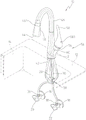
FIG. 1A is a perspective view of an illustrative embodiment faucet of the present invention including a molded waterway assembly mounted to a sink deck and fluidly coupled to hot and cold water supply lines;
FIG. 1B is a perspective view similar to FIG. 1A, showing another illustrative fluid coupling to hot and cold water supply lines;
FIG. 1C is a perspective view similar to FIG. 1A, showing additional illustrative couplings to the hot and cold water supply lines;
FIG. 2 is a perspective view showing an illustrative overmolded coupling assembly for coupling the faucet of FIG. 1A to hot and cold water supply lines;
FIG. 3A is a partially exploded top perspective view of a valve housing assembly of the illustrative embodiment faucet of FIG. 1A;
FIG. 3B is a partially exploded bottom perspective view of the valve housing assembly of FIG. 3A;
FIG. 4 is a cross-sectional view of the valve housing assembly of FIG. 3A;
FIG. 5 is a cross-sectional view of the waterway assembly and cartridge valve assembly of FIG. 4;
FIG. 6 is a partially exploded perspective view of the inner components of the valve housing assembly of FIG. 3A;
FIG. 7 is a top plan view of the base of the molded waterway assembly;
FIG. 8 is a bottom plan view of the base of the molded waterway assembly;
FIG. 9 is a cross-sectional schematic view showing another illustrative fluid coupling arrangement for a waterway assembly;
FIG. 10 is a cross-sectional schematic view similar to FIG. 9, showing a further illustrative fluid coupling for the waterway assembly;
FIG. 11 is a partially exploded perspective view of the faucet of FIG. 1, illustrating the interface between the molded waterway assembly and the cartridge valve assembly; and
FIG. 12 is an exploded perspective view of the cartridge valve assembly.
Detailed Description
The embodiments of the present invention described herein are not intended to be exhaustive or to limit the invention to the precise forms disclosed. Rather, the embodiments selected for description have been chosen to enable one skilled in the art to practice the invention. Although the invention is described in connection with water, it should be understood that other types of fluids may be used.
Referring initially to FIG. 1A, an illustrative embodiment faucet 10 is shown mounted to a mounting deck 12 above a sink or basin 14. Faucet 10 is fluidly coupled to hot and cold water supplies or sources 16 and 18 through conventional stops 20 and 22, respectively. A hot water riser 24 and a cold water riser 26 may fluidly couple the stop 20 and the stop 22 to a hot water inlet fluid delivery component or pipe 28 and a cold water inlet fluid delivery component or pipe 30, respectively. Although fig. 1 illustrates hot and cold water risers 24 and 26 coupled to inlet pipes 28 and 30 by fluid couplings 32 and 34, it should be understood that inlet pipes 28 and 30 may extend uninterrupted from faucet 10 to stops 20 and 22 by fluid couplings 36 and 38, as shown in fig. 1B. Additionally, fig. 1C shows an illustrative embodiment of a piping system in which inlet pipe 28 and inlet pipe 30 are coupled to a building or house behind wall 40. Referring briefly to fig. 2, the fluid couplers 32 and 34 may each illustratively include an overmolded coupler 52 and a mating internally threaded nut 54.
Referring again to fig. 1A-1C, the illustrative faucet 10 further receives an outlet tube 42 to carry tempered water through the illustrative faucet 10 to an outlet 44 of the faucet 10. In the illustrative embodiment shown, the illustrative faucet 10 comprises a pull-down kitchen faucet, wherein an outlet (e.g., spray head) 44 may be configured to move from a body (e.g., delivery flow passage) 46 of the faucet 10 to another location desired by a user. Additionally, the outlet 44 may include a button or other type of trigger 48 that allows water flow to switch between streamlike flow and spray-like flow. In such an embodiment, the outlet tube 42 may comprise a flexible tube that may extend from the distal end 461 of the faucet body 46 to facilitate positioning of the outlet 44 as desired. The outlet tube 42 may include a weight 50 to facilitate replacement of the outlet 44 to a docked position at the distal end 461 of the faucet body 46, as illustrated in fig. 1A-1C. In other embodiments, the faucet 10 may comprise a single-handle bathroom faucet, a single-handle non-drop down kitchen faucet, or various other faucets. In one illustrative embodiment, tubes 28, 30, and 42 may include certain additional features, such as corrugated walls, for improved flexibility.
Referring to fig. 1-4, the illustrative faucet 10 includes a valve housing assembly 56 that includes a handle 58 coupled to the faucet body 46 via a branch or bushing 60, and a valve assembly 3 (fig. 3). As further described herein, in the illustrative embodiment, the handle 58 of the illustrative faucet 10 may be rotated about an axis substantially parallel to the longitudinal axis 62 (fig. 3) of the valve housing assembly 56 or about the longitudinal axis 62 (fig. 3) of the valve housing assembly 56. In further illustrative embodiments, the handle 58 of the faucet 10 may be lifted in a direction substantially away from the faucet body 46, causing pivotal movement about an axis 64 (FIG. 3) that is orthogonal or perpendicular to the longitudinal axis 62 (FIG. 3). In yet another illustrative embodiment, the handle 58 of the faucet 10 may not only be rotatable about an axis substantially parallel to the longitudinal axis 62 (FIG. 3) of the valve housing assembly 56, but may also be elevated in a direction substantially away from the faucet body 46 for pivotal movement about an axis 64 (FIG. 3). For example, in the illustrative embodiment of the faucet 10 shown, with a single cartridge-valve handle, the handle 58 may be lifted to pivot about an axis 64 (fig. 3) to control the water flow rate or rate of the faucet 10, with different angles of the handle 58 corresponding to different water flow rates. Additionally, the handle 58 may be rotated about an axis 62 (fig. 3) to control the temperature of the water flow. In other embodiments, the handle 58 may be rotated about an axis 62 (FIG. 3) to control the water flow rate instead of or in addition to the temperature of the water flow.
Referring now specifically to fig. 3-5, the internal components of the valve housing assembly 56 are shown, including the components of the valve assembly 3. Illustratively, the valve housing body or bonnet 66 is disposed within the bushing 60 of the valve housing assembly 56 via seals 68 (illustratively, labyrinth seals, although other forms of seals are envisioned) and secured to the bushing 60 via screw holes 665 located on a bottom surface 661 of the bonnet 66, screws 601, and screw holes 602 within the bushing 60. In another embodiment, the bonnet housing 66 may be coupled to the liner 60 in other manners (including other fasteners or simply a friction fit formed between the bonnet housing 66 and the seal 68). In embodiments where a seal 68 is used, the seal 68 comprises rubber or another resilient polymer, which facilitates a fluid-tight seal between the seal 68 and the bonnet 66. The bonnet cap 66 may also be attached to the liner 60 by an overmolding process or other manufacturing technique. The bonnet cap 66 includes a sidewall 664 with an inner surface 662. Illustratively, the bonnet cap is cylindrical in shape with an opening 668 opposite the bottom surface 661 that is sized to receive the valve interface member or base 70, and the cartridge valve assembly 72. In other embodiments, the bonnet 66 may comprise other shapes. Illustratively, the bonnet cap 66 is constructed of brass, although other metals or polymers may be used.
The bottom surface 661 of the bonnet cap 66 illustratively includes a cutout 667 configured to receive the boss 701 extending from the valve interface member or the lower surface 702 of the base 70 in a form-fit manner such that the lower surface 702 of the base 70 rests on the top surface 6611 of the bottom surface 661 of the bonnet cap 66. Illustratively, the base 70 is in the form of a disk or disc and includes a hot water inlet opening 703, a cold water inlet opening 704 and a temperature regulated outlet 705 all extending between a lower surface 702 and an upper surface 706, respectively. The outer periphery 707 of the base 70 includes a groove 708 configured to receive a lower annular or radial seal 709. Illustratively, the annular seal 709 includes an O-ring made of rubber or another resilient polymer that facilitates a fluid-tight connection between the base 70 and an inner surface (e.g., inner wall) 662 of the bonnet housing 66 to prevent leakage.
The base 70 further includes a first positioning element (illustratively, a recess 710a and a recess 710b) formed within the upper surface 706 of the base 70. The recesses 710a and 710b are configured to receive second positioning elements (illustratively, pegs 721a and 721b) that are positioned on the bottom of the cartridge valve assembly 72 and extend downwardly from a lower surface 722 of the cartridge valve assembly 72. When assembled, the engagement of the pegs 721 with the recesses 710 causes the cartridge valve assembly to be at least partially disposed within the bonnet 66. In another embodiment, the first positioning element included on the base 70 may include a peg, and the second positioning element on the cartridge valve assembly 72 may include a recess. On an outer periphery 726 of the cartridge valve assembly 72 near the lower surface 722, the cartridge valve assembly 72 includes a groove 727 configured to receive an upper annular or radial seal 728. Illustratively, the annular seal 728 includes an O-ring made of rubber or another resilient polymer that facilitates a fluid-tight connection between the cartridge valve assembly 72 and the inner surface or wall 662 of the bonnet cover 66 to prevent leakage.
In the illustrative embodiment, an upper portion 6621 of the inner wall 662 of the bonnet 66 includes internal threads 6622. When assembled, the lip 729 of the cartridge valve assembly 72 rests just below the threads 6622 so that the remaining upper portion of the cartridge valve assembly 72 can extend above the upper edge 663 of the bonnet 66 while leaving the threads 6622 exposed. The mounting nut 74 is sized to fit snugly over the upper portion of the cartridge valve assembly 72 that remains exposed above the bonnet housing 66. The mounting nut 74 includes external threads 741 that mate with the internal threads 6622 of the bonnet housing 66 to hold the cartridge valve assembly 72 in place within the bonnet housing 66 and compress the cartridge valve assembly 72 and the base 70 together. The mounting nut 74 further includes a groove 742 located above the external threads 741 around an outer periphery of the mounting nut 74, the groove configured to receive the retainer 743. Illustratively, the retainer 743 includes an O-ring composed of rubber or another resilient polymer, which facilitates coupling of the mounting nut 74 with the decorative valve cap 76 for smoother operation of the valve housing assembly 56. The valve cap 76 further covers the valve housing assembly 56 and the internal components of the valve assembly 3 for obtaining an aesthetically pleasing faucet 10.
Referring still to fig. 3-5, the illustrative cartridge valve assembly 72 includes a rod 730 that is received within the handle 58 such that the rod 730 moves with movement of the handle 58 to operate the faucet 10, as further described below. The handle 58 further includes a handle nut 581 that is received within the handle 58 at a substantially orthogonal angle to the rod 730 when received within the handle 58 to hold the rod 730 in place relative to the handle 58. Handle nut 581 is held in place within handle 58 via threads 582 and may be tightened within handle 58 by the use of a tool such as, but not limited to, a screwdriver or drill bit. Nut cover 583 may be received in handle 58 over handle nut 581 to provide an aesthetically pleasing handle 58 and to help retain handle nut 581.
As shown in fig. 4-6, waterway assembly 2 is illustratively positioned within a sleeve 60 of valve housing assembly 56 of faucet 10. Waterway assembly 2 illustratively includes a hot water inlet tube 28, a cold water inlet tube 30, and an outlet tube 42. Further, illustrative waterway assembly 2 includes a base 70 that includes a hot water inlet 703, a cold water inlet 704, and a tempered outlet 705 as mentioned above. The hot water inlet tube 28, the cold water inlet tube 30, and the outlet tube 42 are fluidly coupled to an inlet 703, an inlet 704, and an outlet 705, respectively, in the base 70. As detailed herein, tubes 28, 30, and 42 are illustratively formed of a flexible non-metallic material (such as a polymer).
In the illustrative embodiment, tube 28, tube 30, tube 42, and base 70 are formed from compatible materials (such as polymers), and illustratively are formed from cross-linkable materials, and are thus illustratively non-conductive. As used in the present invention, the cross-linkable material illustratively includes thermoplastics, and mixtures of thermoplastics and thermosets. In one illustrative embodiment, tube 28, tube 30, tube 42, and base 70 are formed from polyethylene that is subsequently cross-linked to form cross-linked Polyethylene (PEX). However, it should be understood that other polymers may be substituted therefor. For example, any Polyethylene (PE) such as polyethylene (PE-RT) resistant to elevated temperatures, polypropylene (PP) such as atactic polypropylene (PPR), or Polybutylene (PB) may be used.
Referring to fig. 4-8, the upper ends 78 of the hot water inlet tube 28, the cold water inlet tube 30, and the outlet tube 42 are positioned in alignment with the inlet 703, the inlet 704, and the outlet 705, respectively, of the base 70. Each of the inlet 703, inlet 704, and outlet 705 includes a counterbore 711 (fig. 8) extending downwardly from the lower surface 702 and defining a stop surface 7111 that mates with the upper ends 78 of the tubes 28, 30, and 42. In the illustrative embodiment, base 70 is overmolded around upper ends 78 of tubes 28, 30, and 42. More specifically, base 70 is formed from a polymer that is molded over previously formed tubes 28, 30, and 42 in the manner detailed herein. The overmolded base 70 partially melts the upper ends 78 of the tubes 28, 30, and 42, thereby forming a bond between the material of the base 70 and the material of the tubes 28, 30, and 42. To facilitate the molding process, inlet 703, inlet 704, and outlet 705, and thus tube 28, tube 30, and tube 42, respectively, are illustratively aligned along a common central axis 712 (fig. 7). Further, as shown in FIG. 8, a support or boss 701 illustratively extends downwardly from a lower surface 702 of the susceptor 70 and surrounds an inlet 703, an inlet 704, and an outlet 705. Boss 701 provides additional support for tubes 28, 30, and 42 coupled to base 70. In the illustrative embodiment, boss 701 includes a ridge 7011 that helps to facilitate proper orientation of waterway assembly 2 with respect to bonnet 66. Although illustrative orientations are depicted in the figures, other ways for orienting waterway assembly 2 with respect to bonnet cap 66 may be appreciated.
In the illustrative embodiment described in detail herein, the base 70 is formed from polyethylene that has been overmolded around the tubes 28, 30, and 42 and subsequently cross-linked. It should be noted that the reinforcing members (e.g., fiberglass) may be disposed within the polyethylene of the base 70. While polymers (such as cross-linkable polyethylene) are illustrative materials for the base 70, in certain embodiments, other materials, such as brass or copper, may be substituted therefor. Additionally, tubes 28, 30, and 42 may be fluidly coupled to base 70 in a variety of ways other than by overmolding, such as ultrasonic welding or heat staking.
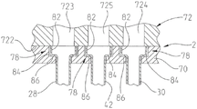
Referring now to fig. 9 and 10, an illustrative alternative means for coupling the tube 28, the tube 30 and the tube 42 is shown. For example, in fig. 9, the upper ends 78 of the tubes 28, 30, and 42 include enlarged portions 82 configured to be received within mating counterbores 84 formed in the base 70. As can be appreciated, each enlarged portion 82 is retained intermediate a lip 86 formed within the counterbore 84 of the base 70 and a lower surface 722 of the cartridge valve assembly 72 (fig. 3-6). Each enlarged portion 82 may illustratively be integrally formed with each tube 28, 30, and 42, respectively, or formed as a separate component, such as an overmold. As shown in the additional illustrative embodiment of fig. 10, the upper end 78 may include external threads 781 that threadably engage internal threads 716 formed within the base 70.
As described in detail herein, base 70 of waterway assembly 2 is illustratively secured to the tube by overmolding. The basic principle of over-molding a pipe connection on a pipe is well known. In the present method, the tubes 28, 30, and 42 are illustratively positioned within a mold (not shown) with a pin or mandrel slid into each respective tube 28, 30, and 42 to prevent them from collapsing during the injection molding process. The mold receives the parallel aligned ends of tubes 28, 30 and 42 and then receives a flowable polymer (illustratively polyethylene) that forms a suitable base 70. As described in further detail herein, the upper ends 78 of the tubes 28, 30, and 42 are aligned along a common axis 715 to facilitate opening and closing of the portions of the mold. After the polymer has hardened sufficiently, the mold is opened to release base 70 and tube 28, tube 30 and tube 42. By overmolding, each end 78 of each tube 28, 30, and 42 partially melts and bonds with the overmolded material of base 70 to form a substantially unitary assembly, such as waterway assembly 2.
As is well known, polyethylene is flexible or semi-rigid and can be crosslinked to form PEX. Crosslinked polyethylene links individual molecular chains together and prevents cleavage. The curing or crosslinking process may be formed using any of several different techniques, such as PEX-A, PEX-B or PEX-C. PEX-a is formed by crosslinking polyethylene using a peroxide. More particularly, PEX-a is formed from polyethylene having peroxide incorporated therein. When peroxide polyethylene is heated above the decomposition temperature of the peroxide, "free" radicals are generated to initiate the crosslinking process. PEX-B is formed by crosslinking polyethylene using silane. PEX-B is formed by using silane grafted polyethylene (which is then "moisture cured," also known as sauna cured, by exposure to heat and water). PEX-C is formed from polyethylene, which is crosslinked by bombarding it with electromagnetic (γ) or high-energy electron (β) radiation.
By overmolding, a material-to-material bond may be achieved, providing a substantially leak-proof coupling between the tubes 28, 30, and 42 and the base 70. The resulting overmolded assembly is then crosslinked by means known in the art, for example, peroxide crosslinking, silane crosslinking, radiation crosslinking, and the like. More specifically and as described in detail above, the crosslinking may be performed by a silane process or a peroxide process or a combination thereof, wherein the crosslinking is done in a hot bath. Each process has a crosslinking catalyst that crosslinks the polymer when certain temperatures, pressures, and/or humidities are used. In an illustrative embodiment, the assembly is passed under an irradiation unit, and exposure results in crosslinking. While the final product is illustratively cross-linked, in some cases it may be suitable to cross-link the individual components 28, 30, 42 and 70. In further illustrative embodiments, the material for the base 70 may be partially cross-linked prior to overmolding, and then further cross-linked after coupling to the tubes 28, 30, and 42.
Referring to fig. 11 and as mentioned above, cartridge valve assembly 72 is supported by base 70 of waterway assembly 2. As discussed above, the pegs 721a and 721b are illustratively positioned on the lower surface 722 of the cartridge valve assembly 72 and extend downwardly from the lower surface 722 of the cartridge valve assembly 72; corresponding recesses 710a and 710b are formed in the upper surface 706 of the pedestal 70. The location of the pegs 721 within the recesses 710 facilitates proper orientation of the cartridge valve assembly 72 relative to the molded waterway assembly 2, and thus alignment of the tubes 28, 30, and 42, and the corresponding inlet 703, inlet 704, and outlet 705 with the hot water port 723, cold water port 724, and tempered water port 725 of the cartridge valve assembly 72, respectively. Additionally, hot flow guide 713, cold flow guide 714 and tempered water flow guide 715 are formed in the upper surface 706 of the base 70 to facilitate fluid flow between the inlet 703, inlet 704, outlet 705 and the corresponding ports 723, 724 and 725, respectively.
As a result of the above-described structure, the hot water inlet tube 28 places the hot water supply 16 (FIG. 1) in fluid communication with the cartridge valve assembly 72 via the hot water inlet 703 of the base 70 and the hot water port 723 of the cartridge valve assembly 72. Likewise, the cold water inlet tube 30 places the cold water supply 18 (FIG. 1) in fluid communication with the cartridge valve assembly 72 via the cold water inlet 704 and the cold water port 724 of the cartridge valve assembly 72. The outlet tube 42 places the cartridge valve assembly 72 in fluid communication with the outlet 44 of the faucet 10 via the tempered water port 725. The engagement between the pegs 721 and the recesses 710 may also improve resistance to torque generated between the cartridge valve assembly 72 and the base 70 during operation of the faucet 10.
Still referring to the illustrative embodiment of FIG. 11, the lower surface 722 of the cartridge valve assembly 72 sealingly engages a face seal or axial seal (illustratively a silicone gasket 731 received intermediate the base 70 and the cartridge valve assembly 72). Referring to fig. 4, a gasket (face seal) 731 is positioned intermediate the lower annular seal 709 and the upper annular seal 728. The gasket 731 is received in a channel 732 formed in the lower surface 722 of the cartridge valve assembly 72 and seals against a seat 717 formed by the upper surface 706 of the seat 70. Gaskets 731 extend around hot water flow guide 713, cold water flow guide 714, and tempered water flow guide 715 to help prevent undesirable mixing of water within each of channels 713, 714, and 715.
As shown in fig. 12, the illustrative cartridge valve assembly 72 illustratively includes an upper housing 733, a rod assembly 734, a coupling member 735, a carrier 736, a movable disk or member 738, a fixed disk or member 737, a seal 739, and a lower housing 751. The rod assembly 734 illustratively includes a ball 7341 molded from a thermoplastic material over a portion of the rod 730. A longitudinal extension or knuckle 7342 extends downward from the ball 7341. The ball 7341 is configured to transfer the motion of the rod 730 to the movable member 738 through the extension 7342 and the carrier 736.
Referring now to fig. 4, 5 and 12, a securing member 737 is illustratively disposed within the lower housing 751 of the cartridge valve assembly 72 and seated over port 723, port 724 and port 725, with a seal 739 sandwiched between the securing member 737 and an inner face 7511 of the lower housing 751. A seal 739 is illustratively constructed of rubber or another resilient polymer to facilitate a fluid-tight connection between the fixing member 737 and the lower housing 751. The lower fixing member 737 includes a hot water hole 7371, a cold water hole 7372, and a temperature-adjusting or mixing water hole 7373, which correspond to (i.e., are in fluid communication with) the hot water port 723, the cold water port 724, and the outlet port 725, respectively. A movable member 738 is also provided within the cartridge valve assembly 72 and sits on top of the fixed valve member 737. The movable member 738 includes a bottom surface 7381 and a top surface 7382. Bottom surface 7381 contacts top surface 7374 of fixed member 737 and is configured to slide (translate) thereon. Additionally, the bottom surface 7381 of the movable member 738 includes a concave portion 7384 that can selectively communicate with any one or all of the hot water hole 7371, the cold water hole 7372, and the temperature adjusting water hole 7373 of the fixing member 737. The top surface 7382 of the translating member has an opening 7383 sized to fit over the extension 7342 of the lever assembly 734.
Still referring to fig. 4, 5 and 12, the illustrative upper housing 733 includes a projection 7331 that fits within a groove 7352 on the perimeter of the coupling member 735, such that the upper housing 733 may fit over the coupling member 735 and the lever assembly 734 to allow the lever 730 to exit through a hole 7332 at the top of the upper housing 733, allowing the lever 730 to interact with the handle 58. The projection 7331 includes a hole 73311 formed such that the projection 7331 and the hole 73311 can fit within a groove 7512 formed by an outer sidewall 7513 and a projection 7514 of the lower case 751. When assembled, the projection 7514 is inserted into the hole 73311 to facilitate the coupling of the upper case 733 and the lower case 751.
The illustrative cartridge valve assembly 72 may also include a temperature limiting member 752 received intermediate the coupling member 735 and the upper housing 733. The temperature limiting member 752 is configured to limit lateral pivotal movement of the rod 730 and the extension 7342, thus also limiting the maximum allowable temperature of the water flowing through the cartridge valve assembly 72.
As discussed above, the handle 58 is illustratively configured to move in a direction generally away from the faucet body 46. In the rest position as shown in fig. 4, the recess 7384 is in fluid communication with the temperature regulating water hole 7373 of the fixing member 737 and with the temperature regulating water port 725 of the cartridge valve assembly 72. In this position, hot water port 7371 and cold water port 7372 of securing member 737 are blocked by bottom surface 7381 such that they are not in fluid communication with recess 7384. As a result, there is no fluid path between the hot water supply 16 (fig. 1) and/or the cold water supply 18 (fig. 1) and the tempered water port 725. In other embodiments, recess 7384 may not be in fluid communication with any of water hole 7371, water hole 7372, or water hole 7373 of fixing member 737.
As the handle 58 moves, the rod 730 moves with the handle 58, causing the assembly formed by the rod 730 and the handle 58 to pivot about the orthogonal axis 64 (fig. 3), causing the extension 7342 to move. As the extension 7342 moves with the handle 58, the movable member 738 translates across the top surface 7374 of the fixed member 737 such that the recessed portion 7384 of the movable member 738 is in fluid communication with the hot water tube 28 and/or the cold water tube 30 while remaining in fluid communication with the outlet tube 42. In this position, hot water pipe 28 and/or cold water pipe 30 are in fluid communication with outlet pipe 42 via recess 7384 of movable member 738.
For example, referring to fig. 1-5 and 11-12, when in operation, hot water may be supplied from the hot water supply 16 to the hot water pipe 28, enter the hot water flow passage 713 through the hot water inlet 703 of the base 70, pass through the hot water port 723 of the cartridge valve assembly 72, and enter the recess 7384 of the movable member 738 through the hot water hole 7371, and then be released from the recess 7384 of the movable member 738 into the outlet pipe 42 via the attemperation water hole 7373 of the fixed member 737, the attemperation water port 725 of the cartridge valve assembly 72, and the attemperation water flow passage 715 and the attemperation outlet 705 of the base 70. Similarly, when in operation, cold water may be supplied from the cold water supply 18 to the cold water pipe 30, enter the cold water flow passage 714 through the cold water inlet 704 of the base 70, pass through the cold water port 724 of the cartridge valve assembly 72 and enter the recessed portion 7384 of the movable member 738 through the cold water hole 7372, and then be released from the recessed portion 7384 of the movable member 738 into the outlet pipe 42 via the attemperation water hole 7373 of the fixed member 737, the attemperation water port 725 of the cartridge valve assembly 72, and the attemperation water flow passage 715 and the attemperation outlet 705 of the base 70.
As the rod 730 rotates with the handle 58, the movable member 738 rotates. When the faucet 10 is operable and the recess 7384 of the movable member 738 is in fluid communication with the water supplies 16 and 18, rotation of the handle 58 about the longitudinal axis 62 determines the temperature of the water disposed into the outlet tube 42. For example, if rotation of the handle 58 causes the recess 7384 to communicate more with the hot water supply 16 than with the cold water supply 18, the water disposed into the outlet tube 42 will be warmer than if the recess 7384 communicated more or equally with the cold water supply 18 than with the hot water supply 16.
As can be appreciated, the illustrative faucet 10 described in detail above is configured to prevent leakage both below and above the mount or sink deck. More specifically, a gasket or face seal 731 provides a primary seal that prevents water leakage between cartridge valve assembly 72 and base 70 of waterway assembly 2. The lower annular seal 709 and the upper annular seal 728 prevent leakage from the exterior of the bonnet cover 66 if leakage occurs at the interface between the cartridge valve assembly 72 and the base 70. Alternatively, the pressurized water from the inlet tubes 28 and 30 is directed to the environment through the outlet tube 42 extending within the delivery flow passage 46.
While the invention has been described in detail with reference to certain preferred embodiments, variations and modifications exist within the spirit and scope of the invention as described and defined in the claims. Likewise, although the invention has been described in detail with reference to water flow, other fluids consistent with the described invention may also be used.
Claims (25)
1. A faucet assembly, comprising:
a housing body including a sidewall defining an opening;
a cartridge valve assembly received within an opening of the housing body;
An upper annular seal supported by the cartridge valve assembly and configured to engage an inner surface of the housing body;
a base supporting the cartridge valve assembly at a valve interface;
a face seal at the valve interface between the cartridge valve assembly and the base;
a lower annular seal supported by the base and configured to engage an inner surface of the housing body;
a plurality of tubular members having first and second ends, the plurality of tubular members supported by the base and configured to be in fluid communication with the cartridge valve assembly; and
a mounting nut configured to be removably coupled to the housing body within the opening defined by the sidewall, wherein the mounting nut, when tightened, is configured to compress the face seal between the cartridge valve assembly and the base to form a substantially fluid-tight seal.
2. The faucet assembly of claim 1, further comprising a handle coupled to the cartridge valve assembly.
3. The faucet assembly of claim 1, wherein the housing body further comprises an end wall opposite the opening formed by the side wall, the end wall being smaller than an area formed by a perimeter of the side wall.
4. The faucet assembly of claim 1, wherein the cartridge valve assembly includes a lower housing having a recess configured to receive the upper annular seal.
5. The faucet assembly of claim 4, wherein the upper annular seal of the cartridge valve assembly contacts an inner surface of the sidewall of the housing body to form a substantially fluid-tight seal.
6. The faucet assembly of claim 1, wherein the base includes a first face, a second face, and a plurality of openings extending between the first face and the second face, the plurality of openings sized to receive the first end of each of the plurality of tubular members.
7. The faucet assembly of claim 6, wherein the second face of the base includes a boss formed around at least the opening and extending away from a surface of the first face, the boss being shaped to fit in an opening formed by an end wall of the housing body to couple to the housing body.
8. The faucet assembly of claim 7, wherein at least a portion of a surface of the second face of the base contacts an inner surface of an end wall of the housing body when the base and the housing body are coupled.
9. The faucet assembly of claim 1, said base including a groove around a periphery of said base, said groove configured to receive said lower annular seal.
10. The faucet assembly of claim 9, wherein the lower annular seal of the base contacts an inner surface of the sidewall of the housing body to form a substantially fluid-tight seal.
11. The faucet assembly of claim 1, further comprising a valve cap supported by the mounting nut, and an O-ring removably coupling the valve cap to the mounting nut.
12. A faucet assembly, comprising:
a housing body including a sidewall defining an opening;
a cartridge valve assembly received within the opening of the housing body, the cartridge valve assembly having a lower housing with a bottom surface including a plurality of openings, the lower housing including a recess around a perimeter of the lower housing;
a first O-ring received within a groove of a lower housing of the cartridge valve assembly, the first O-ring configured to sealingly engage an inner surface of the housing body;
a base disposed within the housing body, the base comprising a first face, a second face, and a plurality of openings extending between the first face and the second face, wherein the plurality of openings of the base are configured to align with the plurality of openings of a cartridge valve assembly;
A plurality of tubular members having first and second ends, the first ends being received by the openings of the base; and
a mounting nut configured to be detachably coupled to the housing body within the opening defined by the sidewall; and
a face seal intermediate the cartridge valve assembly and the base, wherein the mounting nut, when tightened, is configured to compress the face seal between the cartridge valve assembly and the base to form a substantially fluid-tight seal.
13. The faucet assembly of claim 12, further comprising a valve cap supported by the mounting nut, and an O-ring removably coupling the valve cap to the mounting nut.
14. The faucet assembly of claim 12, further comprising a handle coupled to the cartridge valve assembly.
15. The faucet assembly of claim 12, wherein the base is overmolded around the first ends of the plurality of tubular members.
16. The faucet assembly of claim 15, wherein the base and the plurality of tubular members are formed of cross-linked polyethylene.
17. The faucet assembly of claim 12, further comprising a second O-ring supported by the base and configured to sealingly engage an inner surface of the housing body, the face seal being positioned intermediate the first and second O-rings.
18. A faucet assembly, comprising:
a housing body including a sidewall defining an opening;
a cartridge valve assembly received within an opening of the housing body;
a waterway assembly including a base supporting the cartridge valve assembly;
a face seal between the cartridge valve assembly and the base of the waterway assembly;
an upper radial seal between the cartridge valve assembly and an inner surface of the housing body, the upper radial seal positioned above the face seal; and
a lower radial seal between the base and an inner surface of the housing body, the lower radial seal positioned below the face seal.
19. The faucet assembly of claim 18 wherein the waterway assembly further comprises a plurality of tubular members having first and second ends, the first ends being received by the openings of the base.
20. The faucet assembly of claim 18, further comprising a handle coupled to the cartridge valve assembly.
21. The faucet assembly of claim 18, wherein the housing body further comprises an end wall opposite the opening formed by the side wall, the end wall being smaller than an area formed by a perimeter of the side wall.
22. The faucet assembly of claim 18, wherein the cartridge valve assembly includes a lower housing having a recess configured to receive the upper radial seal.
23. The faucet assembly of claim 18, wherein the base includes a groove around a periphery of the base, the groove configured to receive the lower radial seal.
24. The faucet assembly of claim 18, further comprising a mounting nut configured to be removably coupled to the housing body within the opening defined by the sidewall.
25. The faucet assembly of claim 24, further comprising a valve cap supported by the mounting nut, and an O-ring removably coupling the valve cap to the mounting nut.
Applications Claiming Priority (2)
| Application Number | Priority Date | Filing Date | Title |
|---|---|---|---|
| US16/451,846 | 2019-06-25 | ||
| US16/451,846 US11092250B2 (en) | 2019-06-25 | 2019-06-25 | Valve cartridge housing assembly |
Publications (2)
| Publication Number | Publication Date |
|---|---|
| CN112128421A CN112128421A (en) | 2020-12-25 |
| CN112128421B true CN112128421B (en) | 2022-07-29 |
Family
ID=73850618
Family Applications (1)
| Application Number | Title | Priority Date | Filing Date |
|---|---|---|---|
| CN202010577926.2A Active CN112128421B (en) | 2019-06-25 | 2020-06-23 | Tap assembly |
Country Status (3)
| Country | Link |
|---|---|
| US (2) | US11092250B2 (en) |
| CN (1) | CN112128421B (en) |
| CA (2) | CA3211658A1 (en) |
Families Citing this family (3)
| Publication number | Priority date | Publication date | Assignee | Title |
|---|---|---|---|---|
| US11365817B2 (en) * | 2020-09-10 | 2022-06-21 | Kuching International Ltd. | High flow valve seat for water control valve |
| CN113669081B (en) * | 2021-09-07 | 2022-02-11 | 河北东风世景轨道有限公司 | Valve and pouring system are pour to concrete pressurize cloth |
| US11953105B2 (en) | 2022-08-31 | 2024-04-09 | Delta Faucet Company | Valve cartridge assembly |
Citations (6)
| Publication number | Priority date | Publication date | Assignee | Title |
|---|---|---|---|---|
| CN101067307A (en) * | 2006-05-03 | 2007-11-07 | Kwc股份公司 | Internal housing for a sanitary fitting and sanitary fitting |
| CN103291954A (en) * | 2006-05-26 | 2013-09-11 | 印第安纳马斯科公司 | Faucet including a molded waterway assembly |
| CN103322234A (en) * | 2012-03-22 | 2013-09-25 | As知识产权控股有限公司 | Hybrid faucet assembly and water way for same |
| CN103912693A (en) * | 2014-02-28 | 2014-07-09 | 珠海市舒丽玛温控卫浴设备有限公司 | Single-handle double-control thermostatic valve with micro adjustment function |
| CN106286931A (en) * | 2015-06-23 | 2017-01-04 | 科勒公司 | Faucet valve housing unit |
| CN109630719A (en) * | 2019-01-10 | 2019-04-16 | 温州耐洁阀芯有限公司 | Hand divides water temperature adjustment ceramic cartridge |
Family Cites Families (19)
| Publication number | Priority date | Publication date | Assignee | Title |
|---|---|---|---|---|
| US4651770A (en) | 1986-03-28 | 1987-03-24 | Speakman Company | Ceramic disc faucet valve |
| US5316039A (en) | 1993-01-06 | 1994-05-31 | The Chicago Faucet Company | Cartridge-type faucet valve with improved seal |
| US5388805A (en) | 1994-01-03 | 1995-02-14 | C.E.B. Enterprises, Inc. | Dual seal for shut-off valve |
| DE19956401A1 (en) * | 1999-11-24 | 2001-05-31 | Grohe Armaturen Friedrich | Water tap |
| US6123106A (en) * | 1999-12-03 | 2000-09-26 | Emhart Inc. | Thrust washer |
| WO2004015209A1 (en) * | 2002-08-09 | 2004-02-19 | The Meyer Company | Modulator air gap device and faucet including same |
| US7066204B2 (en) | 2003-07-29 | 2006-06-27 | Masco Corporation Of Indiana | Multi-port diverter valve assembly with integral detent |
| WO2005085688A1 (en) | 2004-03-10 | 2005-09-15 | Tatic Pty Ltd | A dual flow valve cartridge |
| US7331359B2 (en) | 2005-04-19 | 2008-02-19 | Kohler Co. | Valve with bi-loading seal |
| US7306005B2 (en) | 2005-12-14 | 2007-12-11 | T&S Brass And Bronze Works, Inc. | Valve and valve cartridge |
| US8991425B2 (en) | 2006-05-26 | 2015-03-31 | Delta Faucet Company | Waterway assembly including an overmolded support plate |
| US20070277889A1 (en) * | 2006-05-31 | 2007-12-06 | Michael Scot Rosko | Mixing valve |
| US7753074B2 (en) | 2006-07-28 | 2010-07-13 | Masco Corporation Of Indiana | Mixing valve |
| US7896025B2 (en) | 2007-06-29 | 2011-03-01 | Masco Corporation Of Indiana | Valve body |
| US8297305B2 (en) | 2008-01-28 | 2012-10-30 | Kohler Co. | Valve assembly having an improved flow path |
| US8156963B2 (en) * | 2008-12-24 | 2012-04-17 | Moen Incorporated | Faucet |
| US8567430B2 (en) * | 2009-10-30 | 2013-10-29 | Masco Corporation Of Indiana | Magnetic coupling for faucet handle |
| CA2882762C (en) * | 2012-09-06 | 2018-01-16 | Masco Corporation Of Indianna | Faucet waterway |
| CN204704428U (en) * | 2015-04-18 | 2015-10-14 | 厦门建霖工业有限公司 | A kind of two depotition cock |
-
2019
- 2019-06-25 US US16/451,846 patent/US11092250B2/en active Active
-
2020
- 2020-05-29 CA CA3211658A patent/CA3211658A1/en active Pending
- 2020-05-29 CA CA3081699A patent/CA3081699C/en active Active
- 2020-06-23 CN CN202010577926.2A patent/CN112128421B/en active Active
-
2021
- 2021-07-30 US US17/389,788 patent/US20210356048A1/en active Pending
Patent Citations (6)
| Publication number | Priority date | Publication date | Assignee | Title |
|---|---|---|---|---|
| CN101067307A (en) * | 2006-05-03 | 2007-11-07 | Kwc股份公司 | Internal housing for a sanitary fitting and sanitary fitting |
| CN103291954A (en) * | 2006-05-26 | 2013-09-11 | 印第安纳马斯科公司 | Faucet including a molded waterway assembly |
| CN103322234A (en) * | 2012-03-22 | 2013-09-25 | As知识产权控股有限公司 | Hybrid faucet assembly and water way for same |
| CN103912693A (en) * | 2014-02-28 | 2014-07-09 | 珠海市舒丽玛温控卫浴设备有限公司 | Single-handle double-control thermostatic valve with micro adjustment function |
| CN106286931A (en) * | 2015-06-23 | 2017-01-04 | 科勒公司 | Faucet valve housing unit |
| CN109630719A (en) * | 2019-01-10 | 2019-04-16 | 温州耐洁阀芯有限公司 | Hand divides water temperature adjustment ceramic cartridge |
Also Published As
| Publication number | Publication date |
|---|---|
| CA3081699C (en) | 2023-10-24 |
| CN112128421A (en) | 2020-12-25 |
| US20210356048A1 (en) | 2021-11-18 |
| CA3211658A1 (en) | 2020-12-25 |
| US11092250B2 (en) | 2021-08-17 |
| CA3081699A1 (en) | 2020-12-25 |
| US20200408313A1 (en) | 2020-12-31 |
Similar Documents
| Publication | Publication Date | Title |
|---|---|---|
| US7819137B2 (en) | Valve mounting assembly | |
| CN112128421B (en) | Tap assembly | |
| US8464748B2 (en) | Waterway connection | |
| US8991425B2 (en) | Waterway assembly including an overmolded support plate | |
| CA2727475C (en) | Widespread faucet | |
| CN102333965B (en) | faucet manifold | |
| US20110079307A1 (en) | Centerset Faucet With Mountable Spout | |
| US20130248005A1 (en) | Hybrid faucet assembly and water way for same | |
| CA2845213C (en) | Faucet including a molded waterway assembly | |
| CA2681259C (en) | Valve mounting assembly | |
| US20040074543A1 (en) | Valving and mixing unit | |
| WO2023060249A1 (en) | Faucet assembly with plastic waterway | |
| NZ527799A (en) | A valving and mixing unit | |
| NZ507962A (en) | Wall mounted mixer assembly, typically for shower, with temperature controller and outlet on front of wall, and hot and cold inlets in or behind wall |
Legal Events
| Date | Code | Title | Description |
|---|---|---|---|
| PB01 | Publication | ||
| PB01 | Publication | ||
| SE01 | Entry into force of request for substantive examination | ||
| SE01 | Entry into force of request for substantive examination | ||
| GR01 | Patent grant | ||
| GR01 | Patent grant |