CN112119552B - electrical users - Google Patents
electrical users Download PDFInfo
- Publication number
- CN112119552B CN112119552B CN201980032685.9A CN201980032685A CN112119552B CN 112119552 B CN112119552 B CN 112119552B CN 201980032685 A CN201980032685 A CN 201980032685A CN 112119552 B CN112119552 B CN 112119552B
- Authority
- CN
- China
- Prior art keywords
- frame
- cover
- electrical
- configuration
- user
- Prior art date
- Legal status (The legal status is an assumption and is not a legal conclusion. Google has not performed a legal analysis and makes no representation as to the accuracy of the status listed.)
- Active
Links
Images


Classifications
-
- H—ELECTRICITY
- H02—GENERATION; CONVERSION OR DISTRIBUTION OF ELECTRIC POWER
- H02G—INSTALLATION OF ELECTRIC CABLES OR LINES, OR OF COMBINED OPTICAL AND ELECTRIC CABLES OR LINES
- H02G3/00—Installations of electric cables or lines or protective tubing therefor in or on buildings, equivalent structures or vehicles
- H02G3/02—Details
- H02G3/08—Distribution boxes; Connection or junction boxes
- H02G3/14—Fastening of cover or lid to box
-
- H—ELECTRICITY
- H02—GENERATION; CONVERSION OR DISTRIBUTION OF ELECTRIC POWER
- H02G—INSTALLATION OF ELECTRIC CABLES OR LINES, OR OF COMBINED OPTICAL AND ELECTRIC CABLES OR LINES
- H02G3/00—Installations of electric cables or lines or protective tubing therefor in or on buildings, equivalent structures or vehicles
- H02G3/02—Details
- H02G3/08—Distribution boxes; Connection or junction boxes
- H02G3/081—Bases, casings or covers
-
- H—ELECTRICITY
- H02—GENERATION; CONVERSION OR DISTRIBUTION OF ELECTRIC POWER
- H02G—INSTALLATION OF ELECTRIC CABLES OR LINES, OR OF COMBINED OPTICAL AND ELECTRIC CABLES OR LINES
- H02G3/00—Installations of electric cables or lines or protective tubing therefor in or on buildings, equivalent structures or vehicles
- H02G3/02—Details
- H02G3/08—Distribution boxes; Connection or junction boxes
- H02G3/12—Distribution boxes; Connection or junction boxes for flush mounting
Landscapes
- Engineering & Computer Science (AREA)
- Architecture (AREA)
- Civil Engineering (AREA)
- Structural Engineering (AREA)
- Casings For Electric Apparatus (AREA)
- Battery Mounting, Suspending (AREA)
- Steroid Compounds (AREA)
- Saccharide Compounds (AREA)
- Connector Housings Or Holding Contact Members (AREA)
- Connection Or Junction Boxes (AREA)
- Telephone Set Structure (AREA)
Abstract
一种电气用户,包括:‑嵌入式箱(7);‑施加于该箱(7)的框架(2);‑用于覆盖框架(2)的盖子(3),盖子3可从框架(2)移除并包括:i)可充电电池(32);ii)电气设备(31)。

An electrical user comprising: - a built-in box (7); - a frame (2) applied to the box (7); - a cover (3) for covering the frame (2), the cover 3 being accessible from the frame (2) ) removes and includes: i) rechargeable battery (32); ii) electrical equipment (31).
Description
技术领域technical field
本发明涉及电气用户。The present invention relates to electrical users.
背景技术Background technique
允许家庭智能化控制的电子设备是已知的。它们包括嵌入式墙显示器,其定义了用户通过其能与家用应用程序交互的用户界面。Electronic devices that allow intelligent control of the home are known. They include embedded wall displays that define the user interface through which users can interact with home applications.
发明内容SUMMARY OF THE INVENTION
本发明的目的是提出一种允许使用的最大灵活性的电气用户。本发明的另一目的是优化建筑物中部分存在的基础设施,以便于家庭智能化控件的安装。The aim of the present invention is to propose an electrical user that allows maximum flexibility of use. Another object of the present invention is to optimize the infrastructure partially existing in the building to facilitate the installation of home intelligent controls.
所述技术任务和指定目标基本上由包括在所附权利要求中的一个或多个中阐述的技术特征的电气用户实现。Said technical tasks and specified objectives are substantially achieved by the electrical user comprising the technical features set forth in one or more of the appended claims.
附图说明Description of drawings
本发明的进一步特性和优点将从如附图中所解说的对电气用户的以下指示性的因而非限定性描述中变得更加明显,其中:Further features and advantages of the present invention will become apparent from the following indicative and therefore non-limiting description to electrical users as illustrated in the accompanying drawings, wherein:
-图1和图2以两种不同配置示出了根据本发明的电气用户的细节图;- Figures 1 and 2 show detailed views of an electrical user according to the invention in two different configurations;
-图3-5示出了根据本发明的电气用户的细节图;- Figures 3-5 show detailed views of an electrical user according to the invention;
-图6和10示出了作为图1和2的替换的电气用户的进一步建设性解决方案;- Figures 6 and 10 show further constructive solutions for electrical users as an alternative to Figures 1 and 2;
-图7-9示出了图6和10的电气用户处于其中电插头被插入的配置中;- Figures 7-9 show the electrical user of Figures 6 and 10 in a configuration in which the electrical plug is inserted;
-图11示出了根据本发明的电气用户的细节图。- Figure 11 shows a detailed view of an electrical user according to the invention.
具体实施方式Detailed ways
本发明涉及嵌入式电气用户。The present invention relates to embedded electrical users.
此种电气用户包括:Such electrical users include:
-框架2;-
-用于覆盖框架2的盖子。- Cover to cover
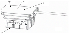
适当地,电气用户包括嵌入式电箱7(通常它可被嵌入到墙中或墙的一部分中)。框架2适用于(或更好地接合在)电箱7中。框架2遮挡电箱7的开口。框架2可包括封闭板,如图2中所例示的。盒子7被连接至电力干线。盖子3至少在打开配置和闭合配置之间可移动。在打开配置中,盖子3允许进入到后面的框架2。与在打开配置中不同,在闭合配置中,盖子3将框架2隐藏在它后面。Suitably, the electrical user includes a built-in electrical box 7 (usually it may be built into the wall or part of the wall).
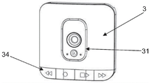
盖子3包括电气设备31。电气设备31意指用作将电用于其自身操作的设备。因此,任何电子设备也是有意的。The
适当地,电气用户包括变压器6。该变压器6操作性地放置在电气设备31的上游。该变压器6被组装到框架2或箱体7上。Suitably, the electrical user includes a transformer 6 . The transformer 6 is operatively placed upstream of the
盖子3包括旨在与其他电子装备交互的无线数据传输和/或接收装置。因此,即使在距框架2一距离处,其操作也不被损害。无线装置是必须的以便与其他设备交互和用于家庭智能化控制。The
有利的是,盖子3可从框架2完全移除。盖子3是便携式的。因此,用户可以从框架2移除盖子3并使用电气设备3,即使在距框架2一距离处。就此而言,盖子3包括用于为所述电气设备31供电的电池。Advantageously, the
在其中盖子3被施加于框架2的配置中,盖子3由电网来供电。在其中盖子3被完全从框架2移除的配置中,电池向电气设备31供电。In the configuration in which the
电池起到缓冲电池的作用。即使当盖子3完全从框架2移除,并且因此不被电力干线供电时,电池也能确保正常工作。这种电池恰适地是可充电类型的。通过利用为箱体7供电的电力干线来为电池充电。这发生在其中盖子3被连接到框架2的至少一个预定配置中。优选地,这发生在其中盖子3被连接到框架2的任何配置中。The battery acts as a buffer battery. The battery ensures proper operation even when the
放置在盖子3中的至少在其受到框架2约束的配置中的电气设备31实际上是电力供电的。适当地,这是通过在框架2中提供的至少一个电触点21来进行的(可能通过电池的插入)。The
框架2还包括用于引导盖子3的引导装置22。引导装置22允许盖子3滑动。优选地,滑动可以是横向的或者在顶部和底部之间。通常这种滑动是平移的。在优选解决方案中,盖子3在横向滑动行程结束时从框架2完全移除。The
盖子3可以包括导电材料条带310;该条带310与所述触点21以对应于不同程度的所述盖子3的开口的多种配置进行电通信。The
条带310与框架2中提供的至少电触点21相组合,限定用于盖子3的横向滑动的至少一部分的滑动电触点。该部分影响盖子3从闭合配置到完全打开的行程的至少60%。这个完整的开口配置是由行程末端定义的。进一步拔出盖子3会导致将盖子从框架2上移除。这可能发生,例如使末端行程(例如,可能是由塑料材料制成的桥台)变形(至少部分以弹性方式)。The
盖子3不一定是可滑动的。例如,在替换解决方案中,盖子3可以是门。在这种情况下,盖子3可具有用于与框架耦合和解耦的装置。The
适当地,盖子3包括所述电气设备31的用户接口34。适当地,用户接口34被设置在盖子3的前表面33上。该用户接口34可以包括显示器,例如具有触摸屏控件。Suitably, the
在图1、2、6-10中,前表面33完全被显示器占据(或在任何情况下至少为70%)。In Figures 1, 2, 6-10, the front surface 33 is completely occupied by the display (or at least 70% in any case).
电气设备31可以是各种类型。例如,它可以包括家庭智能化控制设备。The
设备31可以是扬声器。这适配成在无线模式中与输入信号对接。
如图5中所例示的,设备31可以是用于电话/平板电脑的充电设备(无线或其他)。在这方面,设备31可以定义用于无线充电的电话/平板电脑的至少部分插入的口袋8。As illustrated in Figure 5, the
仍如图5中所例示的,设备31可以是恒温器。在这方面,前表面具有可见的按钮和显示器。Still as illustrated in Figure 5,
在这种情况下,设备31可以包括温度传感器,通过该温度传感器,上述家庭智能化控制设备能够操作温度调节装置(例如,锅炉、热泵、冷却系统等)。In this case, the
如图3中所例示的,设备31可包括用于除臭环境的香味扩散器。例如,在预定或可调整的时间间隔内,设备31释放芳香喷流。在替换解决方案中,它可以释放杀虫剂,而不是芳香剂(例如,用来对抗环境中蚊子的存在)。As illustrated in Figure 3, the
如图4中所例示的,设备31也可以是监视系统。这种监视系统可以是各种类型的。例如,它可以有防盗目的。然而,这种监视系统可以具有监视功能,以监视婴儿、老年人、感觉不好的人等。在这方面,监视系统可以包括摄像机和/或麦克风。监视系统可以在无线模式中传送数据,诸如传送到移动电话。另外,或者作为替代,它可以将这些数据记录在存储器中。As illustrated in Figure 4, the
在进一步的解决方案中,设备31可以包括电流消耗检测装置(也称为流量计)或其它用户的电流消耗检测装置。因此,这将使得检测与电源插座4或与一组电源插座或整个建筑物相关联的电流消耗成为可能。In a further solution, the
设备31可以是允许电话通信的装置。它可以是无绳的,也可以是在其显示屏上复制手机或平板电脑的一个或多个功能。
适当地,用户可包括施加于框架2的至少一个电力/数据传输插座4,该插座4被隐藏。插座4是电插座。它也可以是USB插座、HDMI插座、经由同轴电缆的插座等。插座4被连接至电力干线。有利的是,插座4可被组装到框架2上;在一种替换配置中,插座4可被至少部分地集成到框架2中的单个主体中。Suitably, the user may include at least one power/
插座4至少部分嵌入到电箱7中。在图9中,电箱7被示为与插座4组合,但在替换方案中,盒子7的存在不一定与隐藏的插座4的存在相结合。The
适当地,处于打开配置的盖子3打开插座4,使其从外部可见。在闭合配置中,盖子3通常将插座4隐藏在后面。在闭合配置中,外壳30被标识在框架2和盖子3之间;在闭合配置中,外壳30适配成容纳连接至插座4的电插头。插头如图3和图4中所解说,被插入到插座4中(在这些图中,盖子3是打开的以允许看到后面的插头)。有利地,框架2可以包括檐口23。檐口23适当地围绕到所述壳体30的入口开口。檐口23包括凹槽24,其适于允许/促成电缆的通过(该电缆对于电气用户来说是外来的,但恰恰是被连接到插座4的电器)。凹槽24很重要,因为它允许电缆在盖子3的闭合配置中也通过。Suitably, the
有利地,框架2包括倾斜装置5,其使得定位插座4成为可能。特别地,倾斜装置5可以假设一种配置,其中适于插入插头的插座4的孔组合在同一平面上,该平面基本上平行于闭合配置中的盖子3(参见图3;这种布置允许德国式插头的外壳)。此外,倾斜装置5假设其中它们朝向凹槽24以便于被插入到插座4中的插头的电缆退出的配置(参见图4;这有助于意大利型插头的外壳,或者在任何情况下,插头的触点和插入到插头中的电缆的端子部分沿同一方向延伸)。Advantageously, the
本发明的目的也是一种系统,包括:The object of the present invention is also a system comprising:
-具有上述一个或多个特性的电气用户;- electrical users with one or more of the above characteristics;
-至少一个附加电箱和施加于该附加电箱的附加框架。这个附加的电箱可以是最初目的地是电源插座或电流开关。- at least one additional electrical box and an additional frame applied to the additional electrical box. This additional electrical box may be initially destined for a power outlet or a current switch.
该电气用户的盖子3适用于附加框架,并且在其中它被施加于该附加框架的配置中由附加电箱供电。The electrical user's
本发明达成重要优点。The present invention achieves important advantages.
首先,它使得扩展传统电源箱的操作范围,使其具有新特征并优化组件的布置成为可能。特别是,盖子3构成了可被用于新功能的对象。考虑到它位于电箱处,因此对于收容需要电源的设备来说没有问题。First, it makes it possible to extend the operating range of conventional power boxes with new features and optimize the arrangement of components. In particular, the
另外,盖子3可被移除。因此,当用户在建筑物内移动时,他可以随身携带它,将其用作家庭智能化控制设备(以打开灯、打开百叶窗、打开加热器、启动洗碗机等)。Additionally, the
此外,在建筑物内,有大量的插座分布在各个区域中。因此,可以将盖子3从一个房间移动到另一个房间,并将其插入到各种环境中预先安排好的框架中(以便避免耗尽缓冲电池)。In addition, within a building, there are a large number of sockets distributed in various areas. Thus, the
如被构思的本发明容易受到许多修改和变化的影响,所有这些都落在表征本发明的发明概念的范围内。此外,所有细节都可用其他技术上等效的元素来替换。在实践中,所有使用的材料以及尺寸,可以是根据要求的任何材料以及尺寸。The invention as conceived is susceptible to many modifications and variations, all of which fall within the scope of the inventive concepts that characterize the invention. Furthermore, all details may be replaced by other technically equivalent elements. In practice, all materials and dimensions used may be any material and dimensions as required.
Claims (10)
Applications Claiming Priority (3)
| Application Number | Priority Date | Filing Date | Title |
|---|---|---|---|
| IT102018000005401 | 2018-05-15 | ||
| IT102018000005401A IT201800005401A1 (en) | 2018-05-15 | 2018-05-15 | Electricity |
| PCT/IB2019/053365 WO2019220240A1 (en) | 2018-05-15 | 2019-04-24 | Electrical user |
Publications (2)
| Publication Number | Publication Date |
|---|---|
| CN112119552A CN112119552A (en) | 2020-12-22 |
| CN112119552B true CN112119552B (en) | 2022-10-11 |
Family
ID=63080351
Family Applications (1)
| Application Number | Title | Priority Date | Filing Date |
|---|---|---|---|
| CN201980032685.9A Active CN112119552B (en) | 2018-05-15 | 2019-04-24 | electrical users |
Country Status (7)
| Country | Link |
|---|---|
| US (1) | US11476650B2 (en) |
| EP (1) | EP3794696A1 (en) |
| JP (1) | JP2021524994A (en) |
| CN (1) | CN112119552B (en) |
| CA (1) | CA3099257A1 (en) |
| IT (1) | IT201800005401A1 (en) |
| WO (1) | WO2019220240A1 (en) |
Families Citing this family (1)
| Publication number | Priority date | Publication date | Assignee | Title |
|---|---|---|---|---|
| IT201800005397A1 (en) * | 2018-05-15 | 2019-11-15 | Built-in electric utility |
Family Cites Families (31)
| Publication number | Priority date | Publication date | Assignee | Title |
|---|---|---|---|---|
| US5495402A (en) * | 1992-12-30 | 1996-02-27 | Houssian; Vazgen | Safety night light |
| US5963595A (en) | 1997-09-08 | 1999-10-05 | Tut Systems, Inc. | Method and apparatus for encoding and decoding a bit sequence for transmission over POTS wiring |
| KR20000017735A (en) * | 1998-10-20 | 2000-04-06 | 김동연 | A power supply unit and a portable electronic instrument to be operated by this power supply unit |
| AUPR212700A0 (en) * | 2000-12-18 | 2001-01-25 | Southcorp Australia Pty Ltd | Thermostat to provide a water heater with adaptive adjustment to controlled water temperature |
| US6457843B1 (en) * | 2001-03-09 | 2002-10-01 | Billie-Jo M. Kester | Outlet covering system |
| CN2489497Y (en) * | 2001-05-16 | 2002-05-01 | 蔡建社 | Multipurpose power supply socket |
| JP4467063B2 (en) * | 2005-01-27 | 2010-05-26 | 本田技研工業株式会社 | Slide sheet feeder |
| CN101517851A (en) * | 2005-02-18 | 2009-08-26 | 芯片Pc以色列公司 | Wall mounted housing for insertable computing apparatus |
| US8994276B2 (en) * | 2006-03-28 | 2015-03-31 | Wireless Environment, Llc | Grid shifting system for a lighting circuit |
| CA2676852A1 (en) | 2007-02-02 | 2008-08-07 | Aztech Associates Inc. | Utility monitoring device, system and method |
| JP2009043096A (en) | 2007-08-09 | 2009-02-26 | Fujitsu Ltd | Electronics |
| CN201422025Y (en) * | 2009-06-02 | 2010-03-10 | 郑少民 | Charger capable of being adapted to different plate-type batteries |
| CH701228A1 (en) * | 2009-06-08 | 2010-12-15 | Feller Ag | Electrical apparatus for household installations for arrangement at wall, has wall-fixed socket and supply voltage switch, where apparatus is formed for in-wall mounting or for on-wall mounting |
| US8518569B2 (en) | 2010-03-01 | 2013-08-27 | Apple Inc. | Integrated frame battery cell |
| CN202260515U (en) * | 2011-09-14 | 2012-05-30 | 韩武闯 | Hung-on-door type mine lamp charging device |
| JP2014534405A (en) | 2011-10-21 | 2014-12-18 | ネスト・ラブズ・インコーポレイテッド | User-friendly, networked learning thermostat and related systems and methods |
| CN202495792U (en) * | 2012-03-20 | 2012-10-17 | 深圳市慧通天下科技股份有限公司 | Mobile power pack with rotating plug |
| CN102946028B (en) * | 2012-11-19 | 2015-06-03 | 苏州智绿环保科技有限公司 | Battery box connector |
| US9673598B2 (en) | 2012-11-28 | 2017-06-06 | Hubbell Incorporated | Cover assembly for an electrical box |
| CN203151149U (en) * | 2013-02-23 | 2013-08-21 | 深圳市巨星科技有限公司 | Portable multifunctional mobile power supply |
| ITMI20130909A1 (en) * | 2013-06-03 | 2014-12-04 | 4 Box Srl | BUILT-IN FRAME FOR RETRACTABLE SOCKETS |
| US9557043B2 (en) * | 2013-09-16 | 2017-01-31 | Echostar Technologies L.L.C. | Easy-install home automation light switch |
| ITMI20130355U1 (en) * | 2013-10-15 | 2015-04-16 | A Plastici Azienda Stampaggio Articoli Plasti As | RETRACTABLE MODULE FOR INCASSABILE ELECTRIC FRUITS IN A PLAN. |
| CN104242406B (en) * | 2014-09-29 | 2016-08-24 | 南京视威电子科技股份有限公司 | There is battery and the power conversion output inserter of embedded power conversion interface |
| ES2536573B2 (en) | 2015-02-13 | 2015-11-05 | Raúl BARBOSA SIRGADO | Home automation control system for homes |
| US20170115649A1 (en) * | 2015-08-31 | 2017-04-27 | Deako, Inc. | Occupancy-Based Communication Network |
| ITUB20159599A1 (en) * | 2015-12-28 | 2017-06-28 | Beghelli Spa | CONTROL DEVICE FOR ELECTRIC CONTROL UNITS |
| CN109416991B (en) | 2016-06-03 | 2020-04-21 | 路创技术有限责任公司 | Battery powered retrofit remote control |
| CN207010848U (en) * | 2017-06-01 | 2018-02-13 | 宁波卓翔电子有限公司 | A kind of video doorbell installing mechanism |
| WO2019071192A1 (en) * | 2017-10-06 | 2019-04-11 | Lutron Electronics Co., Inc. | Temperature control device mounted to a sealed electrical wall box |
| KR102626922B1 (en) | 2018-09-21 | 2024-01-18 | 삼성전자주식회사 | See-through type display apparatus including the same |
-
2018
- 2018-05-15 IT IT102018000005401A patent/IT201800005401A1/en unknown
-
2019
- 2019-04-24 CN CN201980032685.9A patent/CN112119552B/en active Active
- 2019-04-24 EP EP19727504.3A patent/EP3794696A1/en active Pending
- 2019-04-24 WO PCT/IB2019/053365 patent/WO2019220240A1/en not_active Ceased
- 2019-04-24 CA CA3099257A patent/CA3099257A1/en active Pending
- 2019-04-24 JP JP2021514498A patent/JP2021524994A/en active Pending
- 2019-04-24 US US17/053,695 patent/US11476650B2/en active Active
Also Published As
| Publication number | Publication date |
|---|---|
| US11476650B2 (en) | 2022-10-18 |
| JP2021524994A (en) | 2021-09-16 |
| WO2019220240A1 (en) | 2019-11-21 |
| CA3099257A1 (en) | 2019-11-21 |
| US20210083462A1 (en) | 2021-03-18 |
| EP3794696A1 (en) | 2021-03-24 |
| IT201800005401A1 (en) | 2019-11-15 |
| CN112119552A (en) | 2020-12-22 |
Similar Documents
| Publication | Publication Date | Title |
|---|---|---|
| US20220200191A1 (en) | Modular consumer-configurable electrical fixture system | |
| US9577389B2 (en) | Systems and methods for modular shock proof electrical outlets | |
| KR101835085B1 (en) | Smart home network system | |
| US9501134B2 (en) | Remotely controllable electrical sockets with plugged appliance detection and identification | |
| US20160191268A1 (en) | Interchangeable Modular Home Automation System | |
| CN112119552B (en) | electrical users | |
| KR20130137976A (en) | Living action detecting system for senior citizen who lives alone | |
| CN112119553B (en) | Embedded electrical users | |
| CN108919666B (en) | Building automation control system | |
| CN105812744A (en) | Active communication monitoring panel | |
| CN109546477A (en) | Intelligent socket for house system | |
| CN106571984B (en) | Electric appliance communication control method and control terminal | |
| CN212542869U (en) | USB extensible intelligent voice socket | |
| CN204858182U (en) | Interior wall -mounted face formula wisdom socket | |
| CN202710099U (en) | Embedded detector | |
| CN217690148U (en) | Intelligent central control device | |
| KR101950963B1 (en) | Internet of things system combined with book desk | |
| CN110247244A (en) | Embedded module electricity box | |
| CN223207341U (en) | A smart central control screen, central control screen host and power box module | |
| CN212725695U (en) | Intelligent switch socket | |
| CN210746875U (en) | Household and outdoor electric liquid mosquito repellent | |
| CN119012591A (en) | Intelligent central control screen | |
| CN204887767U (en) | Control by temperature change panel with mutual mounting structure of strong and weak electricity | |
| CN205900962U (en) | Intelligent multi -jack socket | |
| JP2001283988A (en) | Outlet adapter |
Legal Events
| Date | Code | Title | Description |
|---|---|---|---|
| PB01 | Publication | ||
| PB01 | Publication | ||
| SE01 | Entry into force of request for substantive examination | ||
| SE01 | Entry into force of request for substantive examination | ||
| GR01 | Patent grant | ||
| GR01 | Patent grant |