CN112112298B - Building heat preservation curtain wall construction - Google Patents
Building heat preservation curtain wall construction Download PDFInfo
- Publication number
- CN112112298B CN112112298B CN202011027257.8A CN202011027257A CN112112298B CN 112112298 B CN112112298 B CN 112112298B CN 202011027257 A CN202011027257 A CN 202011027257A CN 112112298 B CN112112298 B CN 112112298B
- Authority
- CN
- China
- Prior art keywords
- matching
- cavity
- plate
- box body
- clamping
- Prior art date
- Legal status (The legal status is an assumption and is not a legal conclusion. Google has not performed a legal analysis and makes no representation as to the accuracy of the status listed.)
- Active
Links
- 238000004321 preservation Methods 0.000 title claims description 21
- 238000010276 construction Methods 0.000 title description 4
- 238000009413 insulation Methods 0.000 claims abstract description 12
- 230000005540 biological transmission Effects 0.000 claims description 16
- 238000009434 installation Methods 0.000 description 7
- 238000012423 maintenance Methods 0.000 description 6
- 230000003139 buffering effect Effects 0.000 description 2
- 238000000034 method Methods 0.000 description 2
- 230000009286 beneficial effect Effects 0.000 description 1
- 230000000694 effects Effects 0.000 description 1
- 238000006467 substitution reaction Methods 0.000 description 1
Images


Classifications
-
- E—FIXED CONSTRUCTIONS
- E04—BUILDING
- E04B—GENERAL BUILDING CONSTRUCTIONS; WALLS, e.g. PARTITIONS; ROOFS; FLOORS; CEILINGS; INSULATION OR OTHER PROTECTION OF BUILDINGS
- E04B1/00—Constructions in general; Structures which are not restricted either to walls, e.g. partitions, or floors or ceilings or roofs
- E04B1/62—Insulation or other protection; Elements or use of specified material therefor
- E04B1/74—Heat, sound or noise insulation, absorption, or reflection; Other building methods affording favourable thermal or acoustical conditions, e.g. accumulating of heat within walls
- E04B1/76—Heat, sound or noise insulation, absorption, or reflection; Other building methods affording favourable thermal or acoustical conditions, e.g. accumulating of heat within walls specifically with respect to heat only
- E04B1/78—Heat insulating elements
- E04B1/80—Heat insulating elements slab-shaped
- E04B1/806—Heat insulating elements slab-shaped with air or gas pockets included in the slab
-
- E—FIXED CONSTRUCTIONS
- E04—BUILDING
- E04B—GENERAL BUILDING CONSTRUCTIONS; WALLS, e.g. PARTITIONS; ROOFS; FLOORS; CEILINGS; INSULATION OR OTHER PROTECTION OF BUILDINGS
- E04B2/00—Walls, e.g. partitions, for buildings; Wall construction with regard to insulation; Connections specially adapted to walls
- E04B2/88—Curtain walls
- E04B2/90—Curtain walls comprising panels directly attached to the structure
- E04B2/92—Sandwich-type panels
Abstract
The invention discloses a building heat-insulation curtain wall structure which comprises a box body, wherein a side swing plate and a swing plate are arranged on the rear side of the box body and are hinged with the box body, a containing cavity is arranged in the box body, locking devices which are locked with each other are arranged between the side swing plate and the swing plate, a heat-insulation device which forms a heat-insulation structure is pulled out of the containing cavity, symmetrical matching plates are arranged in the containing cavity, symmetrical curtain wall plates are arranged in the containing cavity, and clamping devices which are used for clamping the curtain wall plates are arranged on two sides of the box body and one side of the matching plate.
Description
Technical Field
The invention relates to the technical field of building heat-insulating equipment, in particular to a building heat-insulating curtain wall structure.
Background
Among the present building insulation construction, because most curtain possesses heat retaining function, and this curtain adopts the mode of installing from the exterior space mostly, because hang Weiya from the exterior space installation, this has just caused the reliable degree reduction of personnel when actually installing building exterior curtain, and very big messenger personnel's life safety obtains the threat, just because the existence of above-mentioned shortcoming, it is inconvenient to make personnel install the curtain, and because the heat preservation characteristic of single curtain is also lower, also make the curtain lack the setting and carry out whole heat retaining function to the curtain in the in-service use process, this has just caused the equipment to carry out the heat preservation effect reduction in the in-service use, and can not be effectual personnel install the use equipment more convenient, and in the follow-up use difficult maintenance.
Disclosure of Invention
The invention aims to provide a building heat-insulating curtain wall structure, which can solve the problems in the prior art.
The invention is realized by the following technical scheme: the building heat-insulation curtain wall structure comprises a box body, wherein a side swinging plate and a swinging plate are arranged on the rear side of the box body and are hinged with the box body, a containing cavity is formed in the box body, locking devices which are locked with each other are arranged between the side swinging plate and the swinging plate, a heat-insulation device which is pulled out to form a heat-insulation structure is arranged in the containing cavity, symmetrical matching plates are arranged in the containing cavity, symmetrical curtain wall plates are arranged in the containing cavity, and clamping devices which are used for clamping the curtain wall plates are arranged on two sides of the box body and one side of the matching plates.
According to a further technical scheme, the locking device comprises an inner sliding groove arranged in the swing plate, a buffer spring is arranged in the inner sliding groove, a clamping block is arranged in the inner sliding groove in a sliding mode, a side protruding block is arranged on one side of the clamping block, the buffer spring enables the clamping block to be elastically arranged on the end wall of the inner sliding groove, and the clamping block extends into the side swing plate and is fully clamped with the side swing plate.
According to the technical scheme, the heat preservation device comprises a matched rotary drum arranged in the right end wall of the containing cavity, an internal motor is arranged in the box body and drives the matched rotary drum to rotate, symmetrical pull ropes are wound on the outer surface of the matched rotary drum, one end of each pull rope is fixed to the matched rotary drum, and an inflatable heat preservation assembly used for inflating to form a heat preservation structure is arranged on one side of the containing cavity.
According to a further technical scheme, the inflatable heat-insulation assembly comprises an air bag arranged on one side of the accommodating cavity, an air cavity is arranged on one side of the air bag, air holes are formed in the air cavity and communicated with an inflator pump in an external space, symmetrical side convex blocks are arranged on one side of the air bag, the pull rope extends into the side convex blocks, and locking rods in the side convex blocks fix the pull rope in the side convex blocks.
Further technical scheme, dress card device including set up in cooperation draw-in groove in the curtain board, cooperation draw-in groove opening sets up, is provided with middle transmission inner chamber in the rotating cooperation box, middle transmission inner chamber both sides intercommunication is provided with the groove of sliding out, the inslot gliding of sliding out is provided with stretches out the dress fixture block, stretch out the dress fixture block with cooperation draw-in groove dress card setting, the intracavity is provided with the drive of middle transmission stretches out the dress fixture block and is in the drive assembly that slides out the inslot.
A further technical proposal is that the sliding driving component comprises a power rotating motor arranged in the end wall of the intermediate transmission inner cavity, one side of the power rotating motor is provided with a matching rotating rod in a power connection way, two sides of the matching rotating rod are provided with symmetrical guide rods, the guide rods are fixed with the end wall of the intermediate transmission inner cavity, the outer surface of the power rotating motor is provided with a lifting shell in a screw-fit connection way, an internal sliding cavity is arranged in the lifting shell, a push plate is arranged in the internal sliding cavity in a sliding way, one side of the push plate is provided with a side fixing block, the side fixing block penetrates through the lifting shell in a sliding way, a buffer connecting spring is elastically arranged between the push plate and the end wall of the internal sliding cavity, the side fixing block is respectively hinged with the extending clamping blocks at two sides, and the rotating matching box body positioned at one side of the matching plate is connected with the matching plate in a rotating fit way, and the rotating matching box body is driven by a motor in the matching plate to rotate, and a telescopic structure which drives the matching plate to move in a telescopic mode is arranged in the accommodating cavity.
According to a further technical scheme, the telescopic structure comprises pushing cylinders which are arranged in the containing cavity and are symmetrical, pushing telescopic rods are arranged in the pushing cylinders in a power connection mode, and the pushing telescopic rods are fixedly connected with the matching plates in a matching mode.
The invention has the beneficial effects that:
the equipment provided by the invention is simple in structure, the equipment can be unfolded to form an inflatable heat insulation structure to insulate the equipment, and the function of automatically installing the curtain wall plate can be realized, so that the danger coefficient of personnel is reduced, and the personnel can conveniently maintain the curtain wall plate.
When right when the curtain board adorns the card, power rotating motor work back drive the cooperation dwang rotates, makes the lift casing is in cooperation dwang and guide arm outside slide, at this moment because the lift casing slips the back, and the push pedal is in the intracavity that slides inside, just buffering connecting spring plays the function of elastic buffer, makes the side fixed block drives after flexible stretch out and draw back stretch out the dress fixture block and be in the roll-off inslot slides, makes stretch out the dress fixture block with cooperation draw-in groove dress card or break away from the dress card.
When the air bag is unfolded to form a heat-preservation inflation structure, the air pump in the external space is input into the air cavity and the air bag through the air hole to inflate the air bag after working, then the internal motor drives the matching rotary drum to rotate after working, so that the matching rotary drum drives the pull rope to slide and pull after rotating, at the moment, the pull rope drives the air bag to unfold, and the air bag is fully distributed in the containing cavity after being inflated.
When needs are right when the curtain board is maintained and is installed, the difference of maintaining and installing lies in, when maintaining the curtain board and is blocked by dress in the box, during the installation the curtain board, need will the curtain board install in push cylinder one side cooperation board one side, no matter installation or maintenance, can promote after pushing cylinder work the cooperation board carries out the slope and moves, makes the cooperation board drives the curtain board removes, because rotating cooperation box and cooperation board rotate by motor drive, make rotating cooperation box drives the curtain board for the cooperation board rotates, makes the curtain board is convenient for remove, and right the curtain board utilizes stretch out the dress card of dress fixture block and cooperation draw-in groove and control and can realize above-mentioned process the curtain board with the dress card of box.
Drawings
For ease of illustration, the invention is described in detail by the following specific examples and figures.
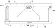
FIG. 1 is a schematic view of the internal overall structure of a building heat-insulating curtain wall structure according to the present invention;
FIG. 2 is a schematic view at A in FIG. 1;
FIG. 3 is a schematic view at B of FIG. 1;
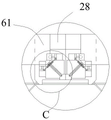
FIG. 4 is a schematic view at C of FIG. 3;
FIG. 5 is a schematic view at D of FIG. 1;
in the figure, a swing plate 11, a pushing cylinder 12, a buffer spring 13, an internal sliding chute 14, a side convex block 15, a clamping block 16, a side swing plate 17, a box body 18, a containing cavity 19, an air hole 21, an air cavity 22, an air bag 23, a locking rod 24, a side convex block 25, a pulling rope 26, a pushing telescopic rod 31, a sliding-out groove 32, an internal sliding cavity 33, a protruding clamping block 34, a matching clamping groove 35, a pushing plate 37, a buffer connecting spring 38, a side fixed block 39, a lifting shell 41, a guide rod 42, a matching rotating rod 43, a power rotating motor 44, an intermediate transmission inner cavity 45, a rotating matching box body 46, an internal motor 51, a matching rotating cylinder 52 and a curtain wall plate 61.
Detailed Description
As shown in fig. 1 to 5, the present invention is explained in detail, and for convenience of description, the following orientations are defined as follows: the building heat-preservation curtain wall structure comprises a box body 18, wherein a side swinging plate 17 and a swinging plate 11 are arranged on the rear side of the box body 18, the side swinging plate 17 and the swinging plate 11 are hinged with the box body 18, a containing cavity 19 is arranged in the box body 18, locking devices which are locked with each other are arranged between the side swinging plate 17 and the swinging plate 11, a heat-preservation device which is pulled out to form a heat-preservation structure is arranged in the containing cavity 19, symmetrical matching plates 28 are arranged in the containing cavity 19, symmetrical curtain wall plates 61 are arranged in the containing cavity 19, and clamping devices for clamping the curtain wall plates 61 are arranged on two sides of the box body 18 and one side of the matching plate 28.
Advantageously, the locking device includes an internal sliding slot 14 disposed in the swing plate 11, a buffer spring 13 is disposed in the internal sliding slot 14, a mounting block 16 is slidably disposed in the internal sliding slot 14, a side protrusion 15 is disposed on one side of the mounting block 16, the buffer spring 13 elastically disposes the mounting block 16 and an end wall of the internal sliding slot 14, and the mounting block 16 extends into the side swing plate 17 to be fully mounted and clamped with the side swing plate 17.
Advantageously, the heat preservation device comprises a matching drum 52 arranged in the right end wall of the cavity 19, an internal motor 51 is arranged in the box 18, the internal motor 51 drives the matching drum 52 to rotate, symmetrical pull ropes 26 are wound on the outer surface of the matching drum 52, one end of each pull rope 26 is fixed with the matching drum 52, and an inflation heat preservation assembly for inflating to form a heat preservation structure is arranged on one side of the cavity 19.
Advantageously, the inflatable insulation assembly comprises an air bag 23 arranged on one side of the cavity 19, an air cavity 22 is arranged on one side of the air bag 23, an air hole 21 is arranged in the air cavity 22, the air hole 21 is communicated with an inflator pump in the external space, symmetrical side protrusions 25 are arranged on one side of the air bag 23, the pull rope 26 extends into the side protrusions 25, and locking rods 24 in the side protrusions 25 fix the pull rope 26 in the side protrusions 25.
Beneficially, wherein, the clamping device includes a matching clamping groove 35 arranged in the curtain wall board 61, the opening of the matching clamping groove 35 is arranged, a middle transmission inner cavity 45 is arranged in the rotating matching box body 46, two sides of the middle transmission inner cavity 45 are communicated with and provided with a sliding groove 32, a protruding clamping block 34 is arranged in the sliding groove 32 in a sliding manner, the protruding clamping block 34 is arranged in the matching clamping groove 35 in a clamping manner, and a sliding driving component for driving the protruding clamping block 34 to slide in the sliding groove 32 is arranged in the middle transmission inner cavity 45.
Beneficially, wherein the sliding driving assembly comprises a power rotating motor 44 arranged in the end wall of the intermediate transmission inner cavity 45, a matching rotating rod 43 is arranged on one side of the power rotating motor 44 in a power connection manner, symmetrical guide rods 42 are arranged on two sides of the matching rotating rod 43, the guide rods 42 are fixed with the end wall of the intermediate transmission inner cavity 45, a lifting shell 41 is arranged on the outer surface of the power rotating motor 44 in a threaded matching manner, an internal sliding cavity 33 is arranged in the lifting shell 41, a push plate 37 is arranged in the internal sliding cavity 33 in a sliding manner, a side fixing block 39 is arranged on one side of the push plate 37, the lifting shell 41 is penetrated by the side fixing block 39 in a sliding manner, a buffer connecting spring 38 is elastically arranged between the push plate 37 and the end wall of the internal sliding cavity 33, and the side fixing block 39 is hinged with the extending clamping blocks 34 on two sides respectively, the rotating matching box body 46 positioned on one side of the matching plate 28 is connected with the matching plate 28 in a rotating matching mode, the rotating matching box body 46 is driven by a motor in the matching plate 28 to rotate, and a telescopic structure which drives the matching plate 28 to move in a telescopic mode is arranged in the accommodating cavity 19.
Advantageously, the telescopic structure comprises pushing cylinders 12 which are symmetrically arranged in the accommodating cavity 19, pushing telescopic rods 31 are arranged in the pushing cylinders 12 in a power connection mode, and the pushing telescopic rods 31 are fixedly connected with the matching plate 28 in a matching mode.
During initial state, above-mentioned device, subassembly and structure are in the out-of-service condition, and this equipment can expand and form gas filled insulation construction and keep warm to equipment to can realize comparatively automatic installation curtain board 61's function makes personnel's danger coefficient reduce and be convenient for personnel maintain curtain board 61.
When right when curtain board 61 adorns the card, power rotating motor 44 drives after the work cooperation dwang 43 rotates, makes lifting housing 41 is in the cooperation dwang 43 slides with the guide arm 42 outside, because at this moment lifting housing 41 slips the back, and push pedal 37 is in inside slides in the chamber 33, just buffering connecting spring 38 plays elastic buffer's function, makes side fixed block 39 drives after the flexibility stretch out dress fixture block 34 and slide in the groove 32 of slipping out, make stretch out dress fixture block 34 with cooperation draw-in groove 35 dress card or break away from the dress card.
When the air bag 23 is expanded to form a heat-preservation inflation structure, the air pump in the external space is input into the air chamber 22 and the air bag 23 through the air hole 21 after working to inflate the air bag 23, and then the internal motor 51 drives the matching rotating drum 52 to rotate after working to drive the pulling rope 26 to slide and pull after the matching rotating drum 52 rotates, so that the pulling rope 26 drives the air bag 23 to expand at the moment, and the air bag 23 is fully distributed in the accommodating cavity 19 after being inflated.
When maintenance and installation of the curtain wall plate 61 are required, the maintenance and installation are distinguished in that the curtain wall plate 61 is already installed and clamped in the housing 18 at the time of maintenance, and when the curtain wall plate 61 is installed, the curtain wall plate 61 is required to be installed on the side of the fitting plate 28 on the side of the pushing cylinder 12, regardless of installation or maintenance, after the pushing cylinder 12 works, the matching plate 28 is pushed to perform an inclined movement, so that the matching plate 28 drives the curtain wall plate 61 to move, because the rotating matching box body 46 and the matching plate 28 are driven by the motor to rotate, the rotating matching box body 46 drives the curtain wall plate 61 to rotate relative to the matching plate 28, so that the curtain wall plate 61 is convenient to move, and the curtain wall plate 61 is controlled by the protruding clamping block 34 and the clamping block matched with the clamping groove 35, so that the clamping of the curtain wall plate 61 and the box body 18 can be realized.
The above description is only an embodiment of the present invention, but the scope of the present invention is not limited thereto, and any changes or substitutions that are not thought of through the inventive work should be included in the scope of the present invention. Therefore, the protection scope of the present invention shall be subject to the protection scope defined by the claims.
Claims (4)
1. A building heat preservation curtain wall structure comprises a box body, wherein a side swing plate and a swing plate are arranged on the rear side of the box body and are hinged to the box body, a containing cavity is formed in the box body, locking devices which are locked with each other are arranged between the side swing plate and the swing plate, a heat preservation device which is pulled out to form a heat preservation structure is arranged in the containing cavity, symmetrical matching plates are arranged in the containing cavity, symmetrical curtain wall plates are arranged in the containing cavity, and clamping devices used for clamping the curtain wall plates are arranged on two sides of the box body and one side of the matching plates;
the clamping device comprises a matched clamping groove arranged in the curtain wall plate, the matched clamping groove is provided with an opening, a middle transmission inner cavity is arranged in a rotating matched box body, two sides of the middle transmission inner cavity are communicated with and provided with sliding grooves, extending clamping blocks are arranged in the sliding grooves in a sliding mode, the extending clamping blocks and the matched clamping grooves are arranged in a clamping mode, and a sliding driving assembly for driving the extending clamping blocks to slide in the sliding grooves is arranged in the middle transmission inner cavity;
wherein, the sliding driving component comprises a power rotating motor arranged in the end wall of the middle transmission inner cavity, one side of the power rotating motor is provided with a matching rotating rod in a power connection way, two sides of the matching rotating rod are provided with symmetrical guide rods, the guide rods are fixed with the end wall of the middle transmission inner cavity, the outer surface of the power rotating motor is provided with a lifting shell in a thread fit way, an inner sliding cavity is arranged in the lifting shell, the inner sliding cavity is internally provided with a push plate in a sliding way, one side of the push plate is provided with a side fixing block which is penetrated through the lifting shell in a sliding way, a buffer connecting spring is elastically arranged between the push plate and the end wall of the inner sliding cavity, the side fixing block is respectively hinged with the extending fixture blocks at two sides, and a rotating matching box body positioned at one side of the matching plate is connected with the matching plate in a rotating fit way, the rotating matching box body is driven by a motor in the matching plate to rotate, and a telescopic structure for driving the matching plate to move telescopically is arranged in the accommodating cavity;
the telescopic structure comprises pushing cylinders which are arranged in the containing cavity and are symmetrical, pushing telescopic rods are arranged in the pushing cylinders in a power connection mode, and the pushing telescopic rods are fixedly connected with the matching plates in a matching mode.
2. The building heat-insulating curtain wall structure as claimed in claim 1, wherein: the locking device comprises an inner sliding groove arranged in the swinging plate, a buffer spring is arranged in the inner sliding groove, a clamping block is arranged in the inner sliding groove in a sliding mode, a side protruding block is arranged on one side of the clamping block, the clamping block is elastically arranged on the end wall of the inner sliding groove through the buffer spring, and the clamping block extends into the side swinging plate and is fully clamped with the side swinging plate.
3. The building heat-insulating curtain wall structure as claimed in claim 1, wherein: the heat preservation device comprises a matched rotary drum arranged in the right end wall of the containing cavity, an internal motor is arranged in the box body and drives the matched rotary drum to rotate, symmetrical pull ropes are wound on the outer surface of the matched rotary drum, one end of each pull rope is fixed to the matched rotary drum, and an inflatable heat preservation assembly used for inflating to form a heat preservation structure is arranged on one side of the containing cavity.
4. The building heat-insulating curtain wall structure as claimed in claim 3, wherein: the inflatable heat-insulation assembly comprises an air bag arranged on one side of the accommodating cavity, an air cavity is arranged on one side of the air bag, air holes are formed in the air cavity and communicated with an inflator pump in the external space, symmetrical side convex blocks are arranged on one side of the air bag, the pull rope extends into the side convex blocks, and locking rods in the side convex blocks fix the pull rope in the side convex blocks.
Priority Applications (1)
| Application Number | Priority Date | Filing Date | Title |
|---|---|---|---|
| CN202011027257.8A CN112112298B (en) | 2020-09-26 | 2020-09-26 | Building heat preservation curtain wall construction |
Applications Claiming Priority (1)
| Application Number | Priority Date | Filing Date | Title |
|---|---|---|---|
| CN202011027257.8A CN112112298B (en) | 2020-09-26 | 2020-09-26 | Building heat preservation curtain wall construction |
Publications (2)
| Publication Number | Publication Date |
|---|---|
| CN112112298A CN112112298A (en) | 2020-12-22 |
| CN112112298B true CN112112298B (en) | 2022-01-28 |
Family
ID=73797039
Family Applications (1)
| Application Number | Title | Priority Date | Filing Date |
|---|---|---|---|
| CN202011027257.8A Active CN112112298B (en) | 2020-09-26 | 2020-09-26 | Building heat preservation curtain wall construction |
Country Status (1)
| Country | Link |
|---|---|
| CN (1) | CN112112298B (en) |
Citations (12)
| Publication number | Priority date | Publication date | Assignee | Title |
|---|---|---|---|---|
| CN102561561A (en) * | 2011-12-29 | 2012-07-11 | 上海玻机幕墙工程有限公司 | Improved thermal insulation curtain wall |
| CN104074305A (en) * | 2014-06-13 | 2014-10-01 | 广东莲田金属工程建筑有限公司 | Self-heat-insulation decoration integral multifunctional light-weight concrete composite plate and curtain wall |
| CN105863127A (en) * | 2016-05-31 | 2016-08-17 | 中民筑友科技投资有限公司 | Exterior wallboard installation node |
| KR20160139789A (en) * | 2015-05-28 | 2016-12-07 | 주식회사 빛나시스템창호 | Curtain wall |
| CN107675817A (en) * | 2017-09-26 | 2018-02-09 | 潘庆阳 | Fast disassembly type building curtain wall |
| CN108716253A (en) * | 2018-06-28 | 2018-10-30 | 浙江解放装饰工程有限公司 | A kind of micro- ventilated energy-saving double-layer curtain wall of heat preservation |
| CN109930954A (en) * | 2019-04-16 | 2019-06-25 | 安徽国泰铝业有限公司 | A kind of coupling type curtain wall unlatching anti-drop device |
| CN110295693A (en) * | 2019-06-26 | 2019-10-01 | 湖北亨威铝业有限公司 | Heat-insulation aluminium alloy Curtain wall with open frame |
| CN210598657U (en) * | 2019-08-09 | 2020-05-22 | 中城建(福建)建筑设计研究院有限公司 | Sunshade heat insulation integration building exterior window |
| CN111335522A (en) * | 2020-05-07 | 2020-06-26 | 福州高新区磊莎玻璃有限公司 | Glass curtain wall capable of being automatically disassembled |
| CN111456481A (en) * | 2020-05-07 | 2020-07-28 | 福州达泰米智能科技有限公司 | Building curtain wall replacing and maintaining device |
| CN111456293A (en) * | 2019-01-22 | 2020-07-28 | 深圳信誉建设集团有限公司 | Building curtain wall ventilation circulation system |
Family Cites Families (1)
| Publication number | Priority date | Publication date | Assignee | Title |
|---|---|---|---|---|
| AT501771B1 (en) * | 2005-01-12 | 2007-03-15 | Thurnher Julius | PREFABRED FACADE ELEMENT |
-
2020
- 2020-09-26 CN CN202011027257.8A patent/CN112112298B/en active Active
Patent Citations (12)
| Publication number | Priority date | Publication date | Assignee | Title |
|---|---|---|---|---|
| CN102561561A (en) * | 2011-12-29 | 2012-07-11 | 上海玻机幕墙工程有限公司 | Improved thermal insulation curtain wall |
| CN104074305A (en) * | 2014-06-13 | 2014-10-01 | 广东莲田金属工程建筑有限公司 | Self-heat-insulation decoration integral multifunctional light-weight concrete composite plate and curtain wall |
| KR20160139789A (en) * | 2015-05-28 | 2016-12-07 | 주식회사 빛나시스템창호 | Curtain wall |
| CN105863127A (en) * | 2016-05-31 | 2016-08-17 | 中民筑友科技投资有限公司 | Exterior wallboard installation node |
| CN107675817A (en) * | 2017-09-26 | 2018-02-09 | 潘庆阳 | Fast disassembly type building curtain wall |
| CN108716253A (en) * | 2018-06-28 | 2018-10-30 | 浙江解放装饰工程有限公司 | A kind of micro- ventilated energy-saving double-layer curtain wall of heat preservation |
| CN111456293A (en) * | 2019-01-22 | 2020-07-28 | 深圳信誉建设集团有限公司 | Building curtain wall ventilation circulation system |
| CN109930954A (en) * | 2019-04-16 | 2019-06-25 | 安徽国泰铝业有限公司 | A kind of coupling type curtain wall unlatching anti-drop device |
| CN110295693A (en) * | 2019-06-26 | 2019-10-01 | 湖北亨威铝业有限公司 | Heat-insulation aluminium alloy Curtain wall with open frame |
| CN210598657U (en) * | 2019-08-09 | 2020-05-22 | 中城建(福建)建筑设计研究院有限公司 | Sunshade heat insulation integration building exterior window |
| CN111335522A (en) * | 2020-05-07 | 2020-06-26 | 福州高新区磊莎玻璃有限公司 | Glass curtain wall capable of being automatically disassembled |
| CN111456481A (en) * | 2020-05-07 | 2020-07-28 | 福州达泰米智能科技有限公司 | Building curtain wall replacing and maintaining device |
Also Published As
| Publication number | Publication date |
|---|---|
| CN112112298A (en) | 2020-12-22 |
Similar Documents
| Publication | Publication Date | Title |
|---|---|---|
| CN210885203U (en) | Anti-falling device for installation of large-scale equipment of oil exploitation platform | |
| RU2006129230A (en) | DEVICE FOR ARTERIAL PRESSURE MEASUREMENT | |
| CN112112298B (en) | Building heat preservation curtain wall construction | |
| CN210564127U (en) | Aluminum alloy door and window with movable assembly | |
| CN106938502B (en) | The installation tool and its application method of a kind of bracket of outdoor machine of air conditioner | |
| CN113276645A (en) | Electronic control water inlet emergency device for automobile | |
| CN112190110A (en) | Electric telescopic curtain rod | |
| CN110754748B (en) | Outdoor multi-functional alpin-stock | |
| CN110217387B (en) | Unmanned aerial vehicle with falling water protection architecture | |
| CN212304249U (en) | Self-locking type inflating cabinet | |
| CN109703581B (en) | Flow guide cover opening and closing mechanism and flow guide cover | |
| CN219081545U (en) | Well shaft blanking plug for throwing and fishing type operation under pressure | |
| CN215565821U (en) | Drilling leaking stoppage bridge-building prevention device | |
| CN109058840A (en) | A kind of energy-saving wall lamp device | |
| CN216380982U (en) | Wireless air bag switch for electric door | |
| CN219138913U (en) | Electronic cat eye | |
| CN113247179B (en) | Easy-to-detach smoke-proof curtain for ship for blocking high-temperature smoke | |
| CN215332464U (en) | Building energy-saving environment-friendly fireproof door and window | |
| CN219205033U (en) | Automatic PLC electric control cabinet of protection | |
| CN219262132U (en) | Barrier-free passage for inward opening door of airtight space | |
| CN220421946U (en) | Dustproof switch | |
| CN214367444U (en) | Durable compression type spring | |
| CN213039198U (en) | Hanging ladder with locking function | |
| CN217326805U (en) | Indoor tool to lock wireless control device | |
| CN217606142U (en) | Optical fiber transmission equipment |
Legal Events
| Date | Code | Title | Description |
|---|---|---|---|
| PB01 | Publication | ||
| PB01 | Publication | ||
| SE01 | Entry into force of request for substantive examination | ||
| SE01 | Entry into force of request for substantive examination | ||
| TA01 | Transfer of patent application right |
Effective date of registration: 20211224 Address after: No.47 Gutan Avenue, economic development zone, Gaochun District, Nanjing City, Jiangsu Province Applicant after: Nanjing Shangbai Architectural Design Consulting Co.,Ltd. Address before: Room 305, building 62, miaobang Jijia community, Kangqiao street, Gongshu District, Hangzhou City, Zhejiang Province Applicant before: Chu Xiaoying |
|
| TA01 | Transfer of patent application right | ||
| GR01 | Patent grant | ||
| GR01 | Patent grant |