Energy-saving air purifier convenient to renew cartridge more
Technical Field
The invention belongs to the technical field of air purification, and particularly relates to an energy-saving air purifier convenient for replacing a filter element.
Background
An air purifier, also known as an air cleaner, an air freshener, and a purifier, refers to a product capable of adsorbing, decomposing, or converting various air pollutants (generally including PM2.5, dust, pollen, odor, formaldehyde, and other decoration pollutants, bacteria, allergens, and the like), and effectively improving air cleanliness, and is mainly classified into household, commercial, and industrial products, and generally, the outdoor purifier increases the use efficiency of a filter element arranged inside due to the influence of the environment.
Application No.: in the patent of CN201810241769.0, the invention discloses an energy-saving air purifier convenient for replacing a filter element, which comprises a main body, an air inlet, an air outlet and a display screen, and further comprises a power generation mechanism and a replacement mechanism, wherein the power generation mechanism comprises an air cylinder, a sliding block and two turnover assemblies, and the replacement mechanism comprises a pushing assembly and a clamping assembly. This energy-saving air purifier convenient to renew cartridge more, through the power generation mechanism, solar cell panel's rotation can be controlled, make full use of daytime solar energy and supply power to equipment, compare with current air purifier, it is more energy-concerving and environment-protective, the use cost of equipment has been reduced, through the renewal mechanism, when having avoided the filter core to change, dust and impurity drop in the inside of equipment, cause the pollution to equipment, influence the use of equipment, compare with current air purifier, it is more convenient that the filter core settles, the damage that the long-time plug of apron caused has been avoided, it is more convenient and reliable to change, air purifier's practicality and reliability have been improved greatly.
Based on the aforesaid, general outdoor purifier is usually for holistic firm effect, and the process is comparatively loaded down with trivial details when causing the filter core in the change, needs a plurality of screws of dismouting etc. and takes place the skew and the dead phenomenon of card in position easily when changing the filter core, comparatively inconvenient problem when clearing up inside fan and top filter screen.
Therefore, in view of the above, research and improvement are made for the existing structure and defects, and an energy-saving air purifier convenient for replacing the filter element is provided, so as to achieve the purpose of higher practical value.
Disclosure of Invention
In order to solve the technical problems, the invention provides an energy-saving air purifier convenient for replacing a filter element, which aims to solve the problems that the conventional purifier is generally used for achieving the integral stabilizing effect, so that the process of replacing the filter element in the purifier is complicated, a plurality of screws and the like need to be disassembled and assembled, the filter element is easy to be inclined and blocked when replaced, and the internal fan and a top filter screen are inconvenient to clean.
The invention is convenient for replacing the filter element of the energy-saving air purifier, and the purpose and the effect are achieved by the following specific technical means:
an energy-saving air purifier convenient for replacing a filter element comprises a shell structure; an air inlet structure is fixedly arranged on the shell structure; the upper end of the air inlet structure is provided with a fan structure; the upper end of the fan structure is clamped with a purification structure; the top end of the purification structure is provided with an air outlet structure; the shell structure is provided with a vertical erection column on still including mount pad, erection column, net board, the mount pad, and articulates respectively on the erection column and installs two net boards, and the net board wholly becomes the arc structure of S, and all has seted up horizontal fluting on every net board, and the fluting is for leaning out' S structure.
Further, the shell structure is characterized in that the two grid plates which are hinged on the magnetic plate and the mounting column are of a staggered structure, the tail ends of the grid plates are of a mutual contact structure, and the magnetic plate is arranged at the tail end contact position of the grid plates.
Further, the air inlet structure is still including air inlet block, net window, strain a section of thick bamboo, air inlet block fixes on the mounting panel, and air inlet block's outer end is articulated installs the door plant, and the door plant all is equipped with net window with air inlet block's outer end, is provided with three in the air inlet block and strains a section of thick bamboo, and vertical straining is carried out the interval through the riser between the section of thick bamboo.
Further, the air inlet structure is characterized by further comprising auxiliary frames, inner sliding grooves, connecting plates and auxiliary frames arranged at the bottoms of the filter cylinders, the three auxiliary frames are fixedly connected through the two connecting plates, the inner sliding grooves are formed in the vertical plates, and the connecting plates are slidably mounted on the inner sliding grooves.
Furthermore, the fan structure further comprises a fan block, a fan wheel, a mounting plate and a fan block, wherein the fan block is installed at the upper end of the air inlet block in a clamping mode, the mounting plate is fixedly installed at the middle layer position of the fan block, four through grooves are formed in the mounting plate, air openings are formed in the middle position of the mounting plate, and the fan wheel is rotatably installed at the upper end and the lower end of the mounting plate by taking the air openings as axes.
Furthermore, the fan structure further comprises a fixing plate, clamping strips and a mounting seat, wherein the fixing plate is hinged to the mounting seat, the hinged position of the fixing plate is set to be tightly attached to the left end of the air inlet block, and five clamping strips are arranged on the inner end face of the fixing plate.
Further, purification structure still fixes the upper end at the fan piece including purifying block, interior filter plate, purifying block installation, purifies the middle level position inside of piece and is fixed with the space stop collar, and the filter plate in the equal joint of upper and lower position at the space stop collar is installed, and interior filter plate adopts the preparation of activated carbon material.
Further, the structure of giving vent to anger still including a gas piece, a board, catching groove, the piece of giving vent to anger installs on the top of purifying the piece, and the catching groove has all been seted up at both ends around the piece of giving vent to anger, and the piece top of giving vent to anger is fixed with a board through the catching groove installation.
Compared with the prior art, the invention has the following beneficial effects:
the setting of shell structure, the waffle slab sets up to the main protective structure in outside of outdoor clarifier, sets up the waffle slab into the structure of S-shaped, can let place and have good aesthetic property at outdoor clarifier, sets up the waffle slab into articulated installation, can change the clarifier of inside and strain convenient opening when straining a section of thick bamboo, the end contact position that intersects of two waffle slabs sets up and is magnetic structure, it is more convenient when making the waffle slab close.
The setting of inlet structure, the effect of realization and the outside intercommunication that two department air inlet windows can be better, the air input that three group's section of thick bamboo in the inlet block can effectual increase clarifier, it is more convenient directly to let the section of thick bamboo of inlet block change through the door plant of articulated installation, when changing the section of thick bamboo of inlet structure, the phenomenon such as card pause can appear and cause a section of thick bamboo to be difficult to take out, the position installation auxiliary frame bottom will be strained, the card that the auxiliary frame can coincide is strained on a section of thick bamboo, connecting plate between the adjacent auxiliary frame can slide in the spout including, thereby realize through the auxiliary frame will strain the mesh that a section of thick bamboo directly taken out, slide including the connecting plate of spout can make the auxiliary frame more steady when moving, thereby reach the purpose of conveniently changing a section.
The setting of fan structure, the purification piece adopts the structure the same with the fan piece, and the interior filter plate that will purify the piece also sets up to be the direction installation from top to bottom, lets the interior filter plate that purifies the piece more swift when changing.
Drawings
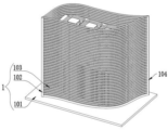
Fig. 1 is a schematic structural view of the present invention.
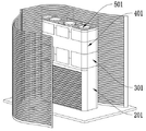
Fig. 2 is a schematic view of the housing structure of the present invention.
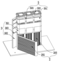
Fig. 3 is a schematic view of the air intake structure of the present invention.
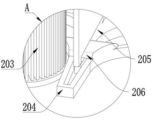
Fig. 4 is a schematic view of the structure of the auxiliary frame of the present invention.
Fig. 5 is a schematic view of the fan structure of the present invention.
Fig. 6 is a partial enlarged structural view of the invention at a in fig. 4.
Fig. 7 is a schematic view of the present invention at a part B enlarged in fig. 5.
In the drawings, the corresponding relationship between the component names and the reference numbers is as follows:
1. a housing structure; 101. a mounting seat; 102. mounting a column; 103. a grid plate; 104. a magnetic plate; 2. an air intake structure; 201. an air inlet block; 202. a grid window; 203. a filter cartridge; 204. an auxiliary frame; 205. an inner chute; 206. a connecting plate; 3. a fan structure; 301. a fan block; 302. a fixing plate; 303. clamping the strip; 304. a fan wheel; 305. mounting a plate; 4. a purification structure; 401. a purification block; 402. an inner filter plate; 5. an air outlet structure; 501. gas outlet block; 502. an air outlet plate; 503. and (6) buckling grooves.
Detailed Description
The embodiments of the present invention will be described in further detail with reference to the drawings and examples. The following examples are intended to illustrate the invention but are not intended to limit the scope of the invention.
In the description of the present invention, "a plurality" means two or more unless otherwise specified; the terms "upper", "lower", "left", "right", "inner", "outer", "front", "rear", "head", "tail", and the like, indicate orientations or positional relationships based on the orientations or positional relationships shown in the drawings, are only for convenience in describing and simplifying the description, and do not indicate or imply that the device or element referred to must have a particular orientation, be constructed in a particular orientation, and be operated, and thus, should not be construed as limiting the invention. Furthermore, the terms "first," "second," "third," and the like are used for descriptive purposes only and are not to be construed as indicating or implying relative importance.
In the description of the present invention, it is to be noted that, unless otherwise explicitly specified or limited, the terms "connected" and "connected" are to be interpreted broadly, e.g., as being fixed or detachable or integrally connected; can be mechanically or electrically connected; may be directly connected or indirectly connected through an intermediate. The specific meanings of the above terms in the present invention can be understood in specific cases to those skilled in the art.
Example (b):
as shown in figures 1 to 7:
the invention provides an energy-saving air purifier convenient for replacing a filter element, which comprises a shell structure 1; an air inlet structure 2 is fixedly arranged on the shell structure 1; the upper end of the air inlet structure 2 is provided with a fan structure 3; the upper end of the fan structure 3 is clamped with a purification structure 4; the top end of the purification structure 4 is provided with an air outlet structure 5; the shell structure 1 further comprises a mounting seat 101, a mounting column 102, grid plates 103, magnetic plates 104, wherein the mounting seat 101 is provided with a vertical mounting column 102, the mounting column 102 is respectively hinged with two grid plates 103, the grid plates 103 are integrally S-shaped, each grid plate 103 is provided with a transverse slot which is of an outward inclined structure, the two grid plates 103 hinged on the mounting column 102 are of a staggered structure, the tail ends of the grid plates 103 are of a mutual contact structure, the magnetic plates 104 are arranged at the contact positions of the tail ends of the grid plates 103, the grid plates 103 are arranged as an external main protection structure of the outdoor purifier, the grid plates 103 are arranged as an S-shaped structure, the purifier placed outdoors can have good aesthetic property, the grid plates 103 are arranged in a hinged manner, and the filter cartridge 203 of the internal purifier can be conveniently opened when being replaced, the magnetic structure is arranged at the end intersection contact position of the two grid plates 103, so that the closing of the grid plates 103 is more convenient.
Wherein, air inlet structure 2 is still including air inlet block 201, net window 202, strain a section of thick bamboo 203, air inlet block 201 is fixed on mounting panel 305, and the articulated door plant of installing in air inlet block 201's outer end, the door plant all is equipped with net window 202 with air inlet block 201's outer end, be provided with three section in the air inlet block 201 and strain a section of thick bamboo 203, vertical straining separates through the riser between 203, it is net window 202 to set up air inlet block 201 rather than on the door plant, and air inlet block 201's both ends all press close to each other with net plate 103, make the effect that realization that two air inlet windows can be better and the outside put through each other, the three groups that strain a section of thick bamboo 203 in air inlet block 201 can the effectual air input of increase clarifier, direct door plant through articulated installation can let air inlet block 201 strain a section of thick bamboo 203.
The air inlet structure 2 further comprises auxiliary frames 204, inner sliding grooves 205, connecting plates 206, the bottom of each filter cylinder 203 is provided with the auxiliary frame 204, three groups of auxiliary frames 204 are fixedly connected with each other through two connecting plates 206, the inner sliding grooves 205 are formed in the vertical plates, the connecting plates 206 are slidably mounted on the inner sliding grooves 205, when the filter cylinders 203 of the air inlet structure 2 are replaced, the filter cylinders 203 are difficult to take out due to the fact that the filter cylinders are jammed and the like, the auxiliary frames 204 are mounted at the positions of the bottoms of the filter cylinders 203, the auxiliary frames 204 can be clamped on the filter cylinders 203 in an inosculating mode, the connecting plates 206 between the adjacent auxiliary frames 204 can slide in the inner sliding grooves 205, the purpose that the filter cylinders 203 are directly taken out through the auxiliary frames 204 is achieved, the connecting plates 206 of the inner sliding grooves 205 can enable the auxiliary frames 204 to move more stably.
Wherein, fan structure 3 still includes fan piece 301, fan wheel 304, mounting panel 305, fan piece 301 joint is installed in the piece 201 upper end of admitting air, the middle level fixed position of fan piece 301 installs mounting panel 305, the logical groove has been seted up everywhere on the mounting panel 305, the wind gap has been seted up to the intermediate position of mounting panel 305, fan wheel 304 uses the wind gap to rotate as the axle center respectively and installs the upper and lower both ends at mounting panel 305, general multilayer fan wheel 304 sets up to direct stack installation, when clearing up fan wheel 304, can comparatively inconveniently need pull down back clearance with outer end fan wheel 304, and install fan wheel 304 sets up to upper and lower two sides, let fan piece 301 can be more convenient in the in-process of clearing up.
Wherein, fan structure 3 is still including fixed plate 302, card strip 303, fixed plate 302 articulates and installs on mount pad 101, and the articulated position of fixed plate 302 sets up to the left end that closely pastes air inlet block 201, be provided with five card strips 303 on the interior terminal surface of fixed plate 302, fixed plate 302 is the main fixed knot structure of clarifier, after clarifier successive layer concatenation installation, with the inside chucking of articulated mounting panel 305 of installing at the left end, because be provided with five card strips 303 on the fixed plate 302, make fixed plate 302 can consolidate fixedly with every layer of work unit through card strip 303, the same when clearing up the clarifier, only need let card strip 303 break away from every work unit with fixed plate 302 outwards swing, thereby make things convenient for the whole dismouting work of clarifier.
Wherein, purification structure 4 is still including purifying block 401, interior filter plate 402, purify the upper end at fan block 301 of 401 installation, the middle level position inside of purifying block 401 is fixed with the space stop collar, filter plate 402 in the equal joint in upper and lower position of space stop collar is installed, interior filter plate 402 adopts the preparation of activated carbon material, purify block 401 and adopt the structure the same with fan block 301, filter plate 402 also sets up to be the direction installation about will purifying block 401, let purifying block 401's interior filter plate 402 more swift when changing.
Wherein, it still includes a gas piece 501 to give vent to anger structure 5, give vent to anger board 502, catching groove 503, the top at purification piece 401 is installed to the piece 501 of giving vent to anger, catching groove 503 has all been seted up at both ends around the piece 501 of giving vent to anger, the piece 501 top of giving vent to anger is fixed with the board 502 of giving vent to anger through catching groove 503 installation, the board 502 joint of giving vent to anger is installed on the catching groove 503 of the piece 501 outer wall of giving vent to anger, make the dismantlement that the board 502 of giving vent to anger can be arbitrary, because the inside of the piece 501 of giving vent to ange.
The specific use mode and function of the embodiment are as follows:
in the invention, the grid plate 103 is set as an external main protection structure of the outdoor purifier, the grid plate 103 is set as an S-shaped structure, the purifier placed outdoors can have good aesthetic property, the grid plate 103 is set to be hinged and installed, the filter cartridge 203 of the internal purifier can be conveniently opened when being replaced, the ends of the two grid plates 103 are crossed and contacted to form a magnetic structure, the grid plate 103 can be more conveniently closed, the two air inlet windows can better realize the effect of communicating with the outside, the three groups of filter cartridges 203 in the air inlet block 201 can effectively increase the air inflow of the purifier, the filter cartridge 203 of the air inlet block 201 can be more conveniently replaced directly through the hinged door plate, the filter cartridge 203 of the air inlet structure 2 can be difficult to take out due to the phenomena of blocking and the like when being replaced, the auxiliary frame 204 is installed at the bottom of the filter cartridge 203, card that auxiliary frame 204 can coincide is on straining a section of thick bamboo 203, connecting plate 206 between the adjacent auxiliary frame 204 can slide in interior spout 205, thereby realize through auxiliary frame 204 with the purpose of straining a section of thick bamboo 203 and directly taking out, slide including spout 205 connecting plate 206 can make auxiliary frame 204 more steady when moving, thereby reach the purpose of conveniently changing a section of thick bamboo 203, it adopts the structure the same with fan piece 301 to purify piece 401, the interior filter plate 402 that will purify piece 401 also sets up and is the installation of direction from top to bottom, let purify the interior filter plate 402 of piece 401 more swift when changing.
The embodiments of the present invention have been presented for purposes of illustration and description, and are not intended to be exhaustive or limited to the invention in the form disclosed. Many modifications and variations will be apparent to those of ordinary skill in the art. The embodiment was chosen and described in order to best explain the principles of the invention and the practical application, and to enable others of ordinary skill in the art to understand the invention for various embodiments with various modifications as are suited to the particular use contemplated.