CN112068412A - Waterproof intelligent positioning student watch with rotation function - Google Patents
Waterproof intelligent positioning student watch with rotation function Download PDFInfo
- Publication number
- CN112068412A CN112068412A CN202011027863.XA CN202011027863A CN112068412A CN 112068412 A CN112068412 A CN 112068412A CN 202011027863 A CN202011027863 A CN 202011027863A CN 112068412 A CN112068412 A CN 112068412A
- Authority
- CN
- China
- Prior art keywords
- block
- rotating
- groove
- wall
- watch
- Prior art date
- Legal status (The legal status is an assumption and is not a legal conclusion. Google has not performed a legal analysis and makes no representation as to the accuracy of the status listed.)
- Pending
Links
Images


Classifications
-
- G—PHYSICS
- G04—HOROLOGY
- G04B—MECHANICALLY-DRIVEN CLOCKS OR WATCHES; MECHANICAL PARTS OF CLOCKS OR WATCHES IN GENERAL; TIME PIECES USING THE POSITION OF THE SUN, MOON OR STARS
- G04B37/00—Cases
- G04B37/08—Hermetic sealing of openings, joints, passages or slits
-
- G—PHYSICS
- G04—HOROLOGY
- G04B—MECHANICALLY-DRIVEN CLOCKS OR WATCHES; MECHANICAL PARTS OF CLOCKS OR WATCHES IN GENERAL; TIME PIECES USING THE POSITION OF THE SUN, MOON OR STARS
- G04B37/00—Cases
- G04B37/04—Mounting the clockwork in the case; Shock absorbing mountings
-
- G—PHYSICS
- G04—HOROLOGY
- G04B—MECHANICALLY-DRIVEN CLOCKS OR WATCHES; MECHANICAL PARTS OF CLOCKS OR WATCHES IN GENERAL; TIME PIECES USING THE POSITION OF THE SUN, MOON OR STARS
- G04B37/00—Cases
- G04B37/08—Hermetic sealing of openings, joints, passages or slits
- G04B37/11—Hermetic sealing of openings, joints, passages or slits of the back cover of pocket or wrist watches
Abstract
The invention discloses a waterproof intelligent positioning student watch with a rotating function, and relates to the technical field of intelligent watches. The intelligent watch is provided with the second connecting block, the rotating groove, the first connecting hole, the rotating block, the second connecting hole, the rotating groove, the rotating column, the rotating chassis and the fixed rotating block, so that the vertical and rotating functions of the intelligent watch can be realized, the rotating block and the second connecting block rotate to realize the vertical function of the intelligent watch, and the fixed rotating block, the rotating column and the rotating chassis rotate by taking the rotating block as a base and taking the inner wall of the rotating groove as a rotating track, so that the 360-degree horizontal rotating function of the intelligent watch can be realized.
Description
Technical Field
The invention relates to the technical field of intelligent watches, in particular to a waterproof intelligent positioning student watch with a rotation function.
Background
The intelligent watch has information processing capacity and meets the basic technical requirements of the watch, the student positioning waterproof intelligent watch has the functions of multiple positioning, two-way conversation, SOS (system on the surface) help seeking, remote monitoring, intelligent loss prevention, historical tracks, electronic fences, pedometers and the like, the safety of students can be ensured, and a healthy and safe growth environment is provided for the students.
The current student intelligence wrist-watch all has the flip function, make surface flip stand, transversely put the arm in the front again, thereby it is convenient to autodyne and with parental's video conversation, but when shooing surrounding environment and thing, then need rotate the arm, because the restriction of arm joint, partial angle rotates very trouble, be not convenient for shoot and shoot, in addition because the angle after the wrist-watch erects can't adjust, need long-time maintenance unified posture in its use, cause the arm easily and ache.
Therefore, the waterproof intelligent positioning student watch with the rotating function and the angle adjusting function is invented
Disclosure of Invention
The invention aims to: in order to solve the problem of unable rotation and unable angle regulation, provide a waterproof intelligent location student's wrist-watch with rotation function.
In order to achieve the purpose, the invention provides the following technical scheme: a waterproof intelligent positioning student watch with a rotating function comprises a base, a fixing mechanism, a rotating mechanism and an angle adjusting mechanism, wherein one end of the base is connected with a second connecting block, the fixing mechanism is positioned at one end of the base, which is far away from the second connecting block, one end of the second connecting block, which is far away from the base, is connected with a first hinge, the first hinge is sleeved with a first watchband, the top end of the first watchband is provided with a buckle hole, one end of the second connecting block, which is far away from the base, is connected with a second hinge, the second hinge is sleeved with a second watchband, the second watchband is sleeved with a fixing sleeve, one end of the second watchband, which is far away from the second hinge, is connected with a watch buckle, the top end of the second connecting block is provided with a rotating groove, two sides of the inner wall of the rotating groove are provided with a, the angle adjusting mechanism is located the top position of slewing mechanism, angle adjusting mechanism's top is connected with the dial plate host computer, the outer wall one end of dial plate host computer is provided with display screen, camera, the camera is located the display screen directly over, outer wall one side of dial plate host computer is provided with emergency button, the outer wall top of dial plate host computer is provided with spacing hole.
Preferably, the fixing mechanism comprises a first connecting block, a first sliding groove, a telescopic groove, a first sliding block, a first connecting rod, a limiting round block, a first spring and a telescopic column, two ends of the outer wall of the first connecting block are respectively connected with the base and the first hinge, the first sliding groove is positioned at the top end of the first connecting block, the telescopic groove is positioned inside the first connecting block and is positioned under the first sliding groove, the first sliding block is positioned right above the first sliding groove, the first connecting rod is connected with the bottom end of the first sliding block and penetrates through the first sliding groove to the inside of the telescopic groove, the limiting round block, the first spring and the telescopic column are positioned inside the telescopic groove, the telescopic column is positioned at one end of the limiting round block, the first spring is the end of the limiting round block far away from the telescopic column, one end of the telescopic column far away from the limiting round block penetrates through the end of the first connecting block close to the outside of the first connecting block, the bottom end of the first connecting rod is connected with the top end of the limiting round block.
Preferably, the rotating mechanism comprises a rotating block, a second connecting hole, a rotating groove, a rotating column, a second sliding groove, a second sliding block, a second connecting rod, a telescopic clamping block and a second spring, the rotating block and the rotating groove are mutually sleeved, the second connecting hole is positioned at one side of the rotating block and close to the bottom end position, the second connecting hole penetrates through two sides of the rotating block, the rotating groove is positioned at the top end of the rotating block, the second sliding groove is positioned at one end of the rotating block, the rotating column is positioned in the rotating groove, the rotating column is positioned at the bottom end position of the inner wall of the rotating groove and is connected with a rotating chassis, the second connecting rod and the inner wall of the second sliding groove are mutually sleeved, the telescopic clamping block is positioned in the second sliding groove, the inside of the second sliding groove is connected with the telescopic clamping block when one end of the second connecting rod penetrates through, and the second sliding block is positioned at, one side of the telescopic fixture block penetrates through one side of the second sliding groove to be in contact with the rotating column in the rotating groove, a groove is formed in the contact position of the telescopic fixture block and the rotating column, one side, away from the groove, of the telescopic fixture block is connected with a limiting block, and the second spring is located inside the second sliding groove and located on one side, away from the telescopic fixture block, of the limiting block.
Preferably, angle adjustment mechanism includes fixed rotatory piece, connection base, No. three connecting holes, a gear piece, angle connecting block, No. two gear pieces and No. four connecting holes, the bottom of fixed rotatory piece is connected with the top of column spinner, connection base, a gear piece are located the top of fixed rotatory piece, connection base is located the both sides of a gear piece, No. three connecting holes are located connection base's outer wall both sides, the angle connecting block is located fixed rotatory piece directly over, No. two gear pieces are located the bottom of angle connecting block, No. four connecting holes are located outer wall one side of angle connecting block, No. four connecting holes run through the both sides of angle connecting block, the top of angle connecting block is connected with the bottom of dial plate host computer.
Preferably, No. two connecting blocks pass through a connecting hole, No. two connecting holes through the dwang with slewing mechanism and are connected fixedly.
Preferably, fixed rotatory piece passes No. three connecting holes, No. three connecting holes through the dwang with the angle connecting block and is connected fixedly, No. one gear piece and No. two gear piece intermeshing.
Preferably, the inner wall of the limiting hole is matched with the outer wall of the telescopic column.
Preferably, the inner wall of the groove is matched with the outer wall of the rotary column, and the diameter of the outer wall of the rotary chassis is larger than that of the outer wall of the rotary column.
Preferably, the diameter of the inner wall of the rotary groove matches the diameter of the outer wall of the rotary chassis.
Compared with the prior art, the invention has the beneficial effects that:
1. the intelligent watch is provided with the second connecting block, the rotating groove, the first connecting hole, the rotating block, the second connecting hole, the rotating groove, the rotating column, the rotating chassis and the fixed rotating block, so that the erecting and rotating functions of the intelligent watch can be realized, the rotating block and the second connecting block rotate to realize the erecting function of the intelligent watch, and the fixed rotating block, the rotating column and the rotating chassis rotate by taking the rotating block as a base and taking the inner wall of the rotating groove as a rotating track, so that the 360-degree horizontal rotating function of the intelligent watch can be realized;
2. according to the intelligent watch, the angle adjusting function of the intelligent watch can be realized by arranging the fixed rotating block, the connecting base, the third connecting hole, the first gear block, the angle connecting block, the second gear block and the fourth connecting hole, the angle connecting block can vertically and reversely rotate by taking the fixed rotating block as the base through the mutual matching of the first gear block and the second gear block, the angle connecting block is fixedly connected with a dial host, and then the angle adjustment of the dial host can be realized through the rotation of the angle connecting block;
3. the dial plate host machine can be detached and used through the arrangement of the rotary groove, the rotary column, the rotary chassis, the second sliding groove, the second sliding block, the second connecting rod, the telescopic clamping block, the groove, the limiting block and the second spring.
Drawings
FIG. 1 is a schematic structural view of the present invention;
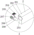
FIG. 2 is a cross-sectional view of the structure of the present invention at location A of FIG. 1;
FIG. 3 is a schematic view of the structure of the present invention with parts connected;
FIG. 4 is a schematic structural diagram of a second connecting block according to the present invention;
FIG. 5 is a schematic structural view of a rotating mechanism of the present invention;
FIG. 6 is a schematic structural view of a fixed rotating block of the present invention;
FIG. 7 is a schematic structural view of an angle connection block of the present invention;
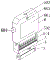
fig. 8 is a schematic structural diagram of the dial host of the present invention;
FIG. 9 is a structural cross-sectional view of the rotating mechanism of the present invention;
fig. 10 is a cross-sectional exploded view of the rotating mechanism of the present invention.
In the figure: 1. a base; 2. a fixing mechanism; 201. a first connecting block; 202. a first chute; 203. a telescopic groove; 204. a first sliding block; 205. a first connecting rod; 206. a limiting round block; 207. a first spring; 208. a telescopic column; 3. a second connecting block; 301. a rotating groove; 302. a first connecting hole; 4. a rotating mechanism; 401. rotating the block; 402. a second connecting hole; 403. a rotating tank; 404. a spin column; 4041. rotating the chassis; 405. a second chute; 406. a second sliding block; 407. a second connecting rod; 408. a telescopic clamping block; 4081. a groove; 4082. a limiting square block; 409. a second spring; 5. an angle adjusting mechanism; 501. fixing the rotating block; 502. a connection base; 503. a third connecting hole; 504. a first gear block; 505. an angle connecting block; 506. a second gear block; 507. a fourth connecting hole; 6. a dial plate host; 601. a display screen; 602. a camera; 603. a limiting hole; 604. an emergency button; 7. a first hinge; 8. a first watchband; 801. buckling holes; 9. a second hinge; 10. a second watchband; 11. fixing a sleeve; 12. and (6) buckling the watch.
Detailed Description
The technical solutions in the embodiments of the present invention will be clearly and completely described below with reference to the drawings in the embodiments of the present invention, and it is obvious that the described embodiments are only a part of the embodiments of the present invention, and not all of the embodiments. All other embodiments, which can be derived by a person skilled in the art from the embodiments given herein without making any creative effort, shall fall within the protection scope of the present invention.
In the description of the present invention, it should be noted that the terms "center", "upper", "lower", "left", "right", "vertical", "horizontal", "inner", "outer", etc., indicate orientations or positional relationships based on the orientations or positional relationships shown in the drawings, and are only for convenience of description and simplicity of description, but do not indicate or imply that the device or element being referred to must have a particular orientation, be constructed and operated in a particular orientation, and thus, should not be construed as limiting the present invention. Furthermore, the terms "first," "second," and "third" are used for descriptive purposes only and are not to be construed as indicating or implying relative importance. In the description of the present invention, it should be noted that, unless otherwise explicitly specified or limited, the terms "mounted," "connected," and "disposed" are to be construed broadly, e.g., as meaning either a fixed connection, a removable connection, or an integral connection; can be mechanically or electrically connected; they may be connected directly or indirectly through intervening media, or they may be interconnected between two elements. The specific meanings of the above terms in the present invention can be understood in specific cases to those skilled in the art. The following describes an embodiment of the present invention based on its overall structure.
Referring to fig. 1-10, a waterproof intelligent positioning student watch with a rotation function comprises a base 1, a fixing mechanism 2, a rotation mechanism 4 and an angle adjusting mechanism 5, wherein one end of the base 1 is connected with a second connecting block 3, the fixing mechanism 2 is positioned at one end of the base 1 far away from the second connecting block 3, one end of the second connecting block 3 far away from the base 1 is connected with a first hinge 7, the first hinge 7 is sleeved with a first watchband 8, the top end of the first watchband 8 is provided with a buckle hole 801, one end of the second connecting block 3 far away from the base 1 is connected with a second hinge 9, the second hinge 9 is sleeved with a second watchband 10, the second watchband 10 is sleeved with a fixing sleeve 11, one end of the second watchband 10 far away from the second hinge 9 is connected with a watch buckle 12, the top end of the second connecting block 3 is provided with a rotation groove 301, two sides of the inner wall of the rotation groove 301 are provided with a first connecting hole, angle adjustment mechanism 5 is located slewing mechanism 4's top position, and angle adjustment mechanism 5's top is connected with dial plate host computer 6, and dial plate host computer 6's outer wall one end is provided with display screen 601, camera 602, and camera 602 is located display screen 601 directly over, and dial plate host computer 6's outer wall one side is provided with emergency button 604, and dial plate host computer 6's outer wall top is provided with spacing hole 603.
Please refer to fig. 2, the fixing mechanism 2 includes a first connecting block 201, a first sliding groove 202, a telescopic groove 203, a first sliding block 204, a first connecting rod 205, a limiting round block 206, a first spring 207 and a telescopic column 208, two ends of an outer wall of the first connecting block 201 are respectively connected with the base 1 and the first hinge 7, the first sliding groove 202 is located at a top end of the first connecting block 201, the telescopic groove 203 is located inside the first connecting block 201 and under the first sliding groove 202, the first sliding block 204 is located right above the first sliding groove 202, the first connecting rod 205 is connected with a bottom end of the first sliding block 204 and penetrates through the first sliding groove 202 to the inside of the telescopic groove 203, the limiting round block 206, the first spring 207 and the telescopic column 208 are located inside the telescopic groove 203, the telescopic column 208 is located at one end of the limiting round block 206, the first spring 207 is an end of the limiting round block 206 far from the telescopic column 208, one end of the telescopic column 208 far from the limiting round block 206 penetrates through an end of the first connecting block 201 close to the outside of the, the bottom of a connecting rod 205 is connected with the top of spacing circle piece 206, and a slider 204 can be moved along the inner wall of flexible groove 203 by bronze drum a connecting rod 205 drive flexible post 208.
Referring to fig. 9-10, the rotating mechanism 4 includes a rotating block 401, a second connecting hole 402, a rotating slot 403, a rotating post 404, a second sliding slot 405, a second sliding block 406, a second connecting rod 407, a retractable latch 408, and a second spring 409, the rotating block 401 is sleeved with the rotating slot 301, the second connecting hole 402 is located at one side of the rotating block 401 and near the bottom end, the second connecting hole 402 penetrates through both sides of the rotating block 401, the rotating slot 403 is located at the top end of the rotating block 401, the second sliding slot 405 is located at one end of the rotating block 401, the rotating post 404 is located inside the rotating slot 403, the rotating post 404 is located at the bottom end of the inner wall of the rotating slot 403 and connected with a rotating chassis 4041, the second connecting rod 407 is sleeved with the inner wall of the second sliding slot 405, the retractable latch 408 is located inside the second sliding slot 405, when one end of the second connecting rod 407 penetrates through, the inside of the second sliding slot 405 is connected with the retractable latch 408, the second sliding block 406, one side of telescopic fixture block 408 runs through one side of No. two spout 405 to inside and the contact of column spinner 403 in groove 403, telescopic fixture block 408 and column spinner 404 contact position are provided with recess 4081, one side that groove 4081 was kept away from to telescopic fixture block 408 is connected with spacing square 4082, No. two spring 409 are located No. two inside spout 405 and are located one side that flexible fixture block 408 was kept away from to spacing square 4082, can realize the rotation function of wrist-watch through slewing mechanism 4, through No. two spout 405, No. two slider 406, No. two connecting rod 407, telescopic fixture block 408 and No. two spring 409 can realize the quick assembly and disassembly function of dial plate host computer 6.
Referring to fig. 6-7, the angle adjusting mechanism 5 includes a fixed rotating block 501, a connecting base 502, a third connecting hole 503, a first gear block 504, angle connecting block 505, No. two gear piece 506 and No. four connecting holes 507, the bottom of fixed rotatory piece 501 is connected with the top of column spinner 404, connection base 502, No. one gear piece 504 is located the top of fixed rotatory piece 501, connection base 502 is located the both sides of a gear piece 504, No. three connecting holes 503 are located the outer wall both sides of connection base 502, angle connecting block 505 is located directly over fixed rotatory piece 501, No. two gear piece 506 is located the bottom of angle connecting block 505, No. four connecting holes 507 are located outer wall one side of angle connecting block 505, No. four connecting holes 507 run through the both sides of angle connecting block 505, the top of angle connecting block 505 is connected with the bottom of dial plate host computer 6, can realize the angle modulation function of dial plate host computer 6 through angle adjustment mechanism 5.
Referring to fig. 3-5, the second connecting block 3 and the rotating mechanism 4 are fixed by rotating the rod through the first connecting hole 302 and the second connecting hole 402, so that the rotating mechanism 4 can rotate with the second connecting block 3 as a base.
Please refer to fig. 3, fig. 6 and fig. 7, the fixed rotary block 501 and the angle connection block 505 are connected and fixed by a rotary rod passing through the third connection hole 503 and the third connection hole 503, and the first gear block 504 and the second gear block 506 are engaged with each other, so that the angle connection block 505 can rotate by using the fixed rotary block 501 as a base.
Please refer to fig. 1 and fig. 2, the inner wall of the limiting hole 603 matches with the outer wall of the telescopic column 208, and the dial host 6 can be fixed and limited by the mutual sleeve connection of the limiting hole 603 and the telescopic column 208.
Referring to fig. 10, the inner wall of the groove 4081 is matched with the outer wall of the rotary column 404, and the diameter of the outer wall of the rotary base 4041 is larger than that of the outer wall of the rotary column 404, so that the telescopic latch 408 only limits the vertical movement of the rotary column 404, and the self-transmission of the rotary column 404 is not affected.
Referring to fig. 9, the inner wall diameter of the rotating slot 403 matches the outer wall diameter of the rotating base 4041, so that the rotating base 4041 can move out of the rotating slot 403 when the retractable latch 408 is retracted.
The working principle is as follows: when the intelligent student watch is normally used, the dial plate host 6 is connected and fixed on the base 1 through the limit hole 603 and the telescopic column 208, the dial plate host 6 and the base 1 are in a horizontal parallel state, and moves along the inner wall of the first sliding groove 202 through the first sliding block 204 and the first connecting rod 205, so that the telescopic column 208 can be driven to move along the inner wall of the telescopic groove 203 and be separated from the limit hole 603, at the moment, the dial plate host 6 can rotate by taking the second connecting block as a base through the rotating mechanism 4 and is adjusted to be in a 90-vertical state with the base 1, at the moment, the dial plate host 6 can horizontally rotate by 360 degrees by taking the rotating block 401 as a base through the fixed rotating block 501, the rotating column 404 and the rotating chassis 4041, in addition, the first gear block 504 and the second gear block 506 can be mutually matched, so that the angle connecting block 505 can rotate in the vertical direction by taking the fixed rotating block as a base, and, because the intelligent watch is worn on the arm, need the arm to keep certain angle when functions such as making a video recording, cause the phenomenon of arm aching easily, consequently can dismantle the use with dial plate host computer 6 when needs, through No. two sliders 406, No. two connecting rods 407 remove along the inner wall of No. two spout 405, can drive flexible fixture block 408 and contract and separate with column spinner 404, shrink when leaving the swivelling chute 403 when flexible fixture block 408, rotatory chassis 4041 can follow the swivelling chute 403 and remove in, can separate dial plate host computer 6 and turning block 401 this moment, the separating operation through dial plate host computer 6 can make the use of intelligent watch more convenient.
It will be evident to those skilled in the art that the invention is not limited to the details of the foregoing illustrative embodiments, and that the present invention may be embodied in other specific forms without departing from the spirit or essential attributes thereof. The present embodiments are therefore to be considered in all respects as illustrative and not restrictive, the scope of the invention being indicated by the appended claims rather than by the foregoing description, and all changes which come within the meaning and range of equivalency of the claims are therefore intended to be embraced therein. Any reference sign in a claim should not be construed as limiting the claim concerned.
Claims (9)
1. The utility model provides a waterproof intelligent location student wrist-watch with rotation function, includes base (1), fixed establishment (2), slewing mechanism (4) and angle adjustment mechanism (5), its characterized in that: one end of the base (1) is connected with a second connecting block (3), the fixing mechanism (2) is positioned at one end, far away from the second connecting block (3), of the base (1), one end, far away from the base (1), of the second connecting block (3) is connected with a first hinge (7), the first hinge (7) is connected with a first watchband (8), a buckle hole (801) is formed in the top end of the first watchband (8), one end, far away from the base (1), of the second connecting block (3) is connected with a second hinge (9), the second hinge (9) is connected with a second watchband (10), the second watchband (10) is connected with a fixing sleeve (11), one end, far away from the second hinge (9), of the second connecting block (10) is connected with a watch buckle (12), the top end of the second connecting block (3) is provided with a rotating groove (301), and first connecting holes (302) are formed in two sides of the inner wall of the rotating groove (, slewing mechanism (4) are located the top position of No. two connecting blocks (3), angle adjustment mechanism (5) are located the top position of slewing mechanism (4), the top of angle adjustment mechanism (5) is connected with dial plate host computer (6), the outer wall one end of dial plate host computer (6) is provided with display screen (601), camera (602) are located display screen (601) directly over, outer wall one side of dial plate host computer (6) is provided with emergency button (604), the outer wall top of dial plate host computer (6) is provided with spacing hole (603).
2. The waterproof intelligent location student's wrist-watch with rotation function of claim 1, characterized in that: the fixing mechanism (2) comprises a first connecting block (201), a first sliding groove (202), a telescopic groove (203), a first sliding block (204), a first connecting rod (205), a limiting round block (206), a first spring (207) and a telescopic column (208), two ends of the outer wall of the first connecting block (201) are respectively connected with the base (1) and the first hinge (7), the first sliding groove (202) is positioned at the top end of the first connecting block (201), the telescopic groove (203) is positioned inside the first connecting block (201) and under the first sliding groove (202), the first sliding block (204) is positioned right above the first sliding groove (202), the first connecting rod (205) is connected with the bottom end of the first sliding block (204) and penetrates through the first sliding groove (202) to the inside of the telescopic groove (203), the limiting round block (206), the first spring (207) and the telescopic column (208) are positioned inside the telescopic groove (203), flexible post (208) are located the one end of spacing circle piece (206), the one end of flexible post (208) is kept away from for spacing circle piece (206) in spring (207), the one end that spacing circle piece (206) were kept away from in flexible post (208) runs through one connecting block (201) and is close to the one end of base (1) to connecting block (201) outside, the bottom of a connecting rod (205) is connected with the top of spacing circle piece (206).
3. The waterproof intelligent location student's wrist-watch with rotation function of claim 1, characterized in that: the rotating mechanism (4) comprises a rotating block (401), a second connecting hole (402), a rotating groove (403), a rotating column (404), a second sliding groove (405), a second sliding block (406), a second connecting rod (407), a telescopic clamping block (408) and a second spring (409), the rotating block (401) is sleeved with the rotating groove (301), the second connecting hole (402) is located on one side of the rotating block (401) and close to the bottom end position, the second connecting hole (402) penetrates through two sides of the rotating block (401), the rotating groove (403) is located at the top end of the rotating block (401), the second sliding groove (405) is located at one end of the rotating block (401), the rotating column (404) is located inside the rotating groove (403), the rotating column (404) is located at the bottom end position of the inner wall of the rotating groove (403) and is connected with a rotating chassis (4041), the second connecting rod (407) is sleeved with the inner wall of the second sliding groove (405), the telescopic clamping block (408) is located inside a second sliding groove (405), when one end of a second connecting rod (407) penetrates through, the inside of the second sliding groove (405) is connected with the telescopic clamping block (408), the second sliding block (406) is located at one end, away from the telescopic clamping block (408), of the second connecting rod (407), one side, running through the one side of the second sliding groove (405), of the telescopic clamping block (408) is in contact with a rotating column (404) inside a rotating groove (403), a groove (4081) is formed in the contact position of the telescopic clamping block (408) and the rotating column (404), one side, away from the groove (4081), of the telescopic clamping block (408) is connected with a limiting block (4082), and the second spring (409) is located inside the second sliding groove (405) and located on one side, away from the limiting block (4082), of the telescopic clamping block (408).
4. The waterproof intelligent location student's wrist-watch with rotation function of claim 1, characterized in that: the angle adjusting mechanism (5) comprises a fixed rotating block (501), a connecting base (502), a third connecting hole (503), a first gear block (504), an angle connecting block (505), a second gear block (506) and a fourth connecting hole (507), the bottom end of the fixed rotating block (501) is connected with the top end of a rotating column (404), the connecting base (502) and the first gear block (504) are located at the top end of the fixed rotating block (501), the connecting base (502) is located on two sides of the first gear block (504), the third connecting hole (503) is located on two sides of the outer wall of the connecting base (502), the angle connecting block (505) is located right above the fixed rotating block (501), the second gear block (506) is located at the bottom end of the angle connecting block (505), the fourth connecting hole (507) is located on one side of the outer wall of the angle connecting block (505), the fourth connecting hole (507) penetrates through two sides of the angle connecting block (505), and the top end of the angle connecting block (505) is connected with the bottom end of the dial plate host (6).
5. The waterproof intelligent location student's wrist-watch with rotation function of claim 1, characterized in that: no. two connecting blocks (3) and slewing mechanism (4) pass a connecting hole (302), No. two connecting holes (402) through the dwang and are connected fixedly.
6. The waterproof intelligent location student's wrist-watch with rotation function of claim 4, characterized in that: fixed rotatory piece (501) and angle connecting block (505) pass No. three connecting holes (503), No. three connecting holes (503) through the dwang and are connected fixedly, No. one gear piece (504) and No. two gear piece (506) intermeshing.
7. The waterproof intelligent location student's wrist-watch with rotation function of claim 1, characterized in that: the inner wall of the limiting hole (603) is matched with the outer wall of the telescopic column (208).
8. The waterproof intelligent location student's wrist-watch with rotation function of claim 3, characterized in that: the inner wall of the groove (4081) is matched with the outer wall of the rotary column (404), and the diameter of the outer wall of the rotary chassis (4041) is larger than that of the outer wall of the rotary column (404).
9. The waterproof intelligent location student's wrist-watch with rotation function of claim 4, characterized in that: the diameter of the inner wall of the rotating groove (403) is matched with the diameter of the outer wall of the rotating chassis (4041).
Priority Applications (1)
| Application Number | Priority Date | Filing Date | Title |
|---|---|---|---|
| CN202011027863.XA CN112068412A (en) | 2020-09-26 | 2020-09-26 | Waterproof intelligent positioning student watch with rotation function |
Applications Claiming Priority (1)
| Application Number | Priority Date | Filing Date | Title |
|---|---|---|---|
| CN202011027863.XA CN112068412A (en) | 2020-09-26 | 2020-09-26 | Waterproof intelligent positioning student watch with rotation function |
Publications (1)
| Publication Number | Publication Date |
|---|---|
| CN112068412A true CN112068412A (en) | 2020-12-11 |
Family
ID=73682699
Family Applications (1)
| Application Number | Title | Priority Date | Filing Date |
|---|---|---|---|
| CN202011027863.XA Pending CN112068412A (en) | 2020-09-26 | 2020-09-26 | Waterproof intelligent positioning student watch with rotation function |
Country Status (1)
| Country | Link |
|---|---|
| CN (1) | CN112068412A (en) |
Cited By (2)
| Publication number | Priority date | Publication date | Assignee | Title |
|---|---|---|---|---|
| CN113671817A (en) * | 2021-08-04 | 2021-11-19 | 杭州芯云道科技有限公司 | Wearable intelligent electronic product capable of being adjusted at multiple angles |
| CN114237008A (en) * | 2021-12-22 | 2022-03-25 | 深圳市新隆达表业有限公司 | Watch with double-layer dial plate |
Citations (8)
| Publication number | Priority date | Publication date | Assignee | Title |
|---|---|---|---|---|
| CN103362915A (en) * | 2013-07-29 | 2013-10-23 | 西继迅达(许昌)电梯有限公司 | Elastic plug structure |
| CN107077100A (en) * | 2015-09-15 | 2017-08-18 | 宰煐斯路泰科株式会社 | convertible intelligent watch |
| CN206930912U (en) * | 2017-07-21 | 2018-01-26 | 台州蜂时电子科技有限公司 | Intelligent watch dial plate and its intelligent watch |
| CN209089008U (en) * | 2018-09-29 | 2019-07-09 | 广东小天才科技有限公司 | One kind can fetching-unloading type smart host structure and its smartwatch |
| CN110133985A (en) * | 2018-09-29 | 2019-08-16 | 广东小天才科技有限公司 | Smart host and intelligent wearable device with the smart host |
| CN110133988A (en) * | 2018-09-29 | 2019-08-16 | 广东小天才科技有限公司 | May be reversed and can rotation smart host and smartwatch |
| CN110703580A (en) * | 2019-10-22 | 2020-01-17 | 出门问问信息科技有限公司 | Wearable device |
| CN111459011A (en) * | 2020-03-25 | 2020-07-28 | 西安易朴通讯技术有限公司 | Intelligent electronic device |
-
2020
- 2020-09-26 CN CN202011027863.XA patent/CN112068412A/en active Pending
Patent Citations (8)
| Publication number | Priority date | Publication date | Assignee | Title |
|---|---|---|---|---|
| CN103362915A (en) * | 2013-07-29 | 2013-10-23 | 西继迅达(许昌)电梯有限公司 | Elastic plug structure |
| CN107077100A (en) * | 2015-09-15 | 2017-08-18 | 宰煐斯路泰科株式会社 | convertible intelligent watch |
| CN206930912U (en) * | 2017-07-21 | 2018-01-26 | 台州蜂时电子科技有限公司 | Intelligent watch dial plate and its intelligent watch |
| CN209089008U (en) * | 2018-09-29 | 2019-07-09 | 广东小天才科技有限公司 | One kind can fetching-unloading type smart host structure and its smartwatch |
| CN110133985A (en) * | 2018-09-29 | 2019-08-16 | 广东小天才科技有限公司 | Smart host and intelligent wearable device with the smart host |
| CN110133988A (en) * | 2018-09-29 | 2019-08-16 | 广东小天才科技有限公司 | May be reversed and can rotation smart host and smartwatch |
| CN110703580A (en) * | 2019-10-22 | 2020-01-17 | 出门问问信息科技有限公司 | Wearable device |
| CN111459011A (en) * | 2020-03-25 | 2020-07-28 | 西安易朴通讯技术有限公司 | Intelligent electronic device |
Cited By (2)
| Publication number | Priority date | Publication date | Assignee | Title |
|---|---|---|---|---|
| CN113671817A (en) * | 2021-08-04 | 2021-11-19 | 杭州芯云道科技有限公司 | Wearable intelligent electronic product capable of being adjusted at multiple angles |
| CN114237008A (en) * | 2021-12-22 | 2022-03-25 | 深圳市新隆达表业有限公司 | Watch with double-layer dial plate |
Similar Documents
| Publication | Publication Date | Title |
|---|---|---|
| CN112068412A (en) | Waterproof intelligent positioning student watch with rotation function | |
| CN209876393U (en) | Intelligent monitoring equipment | |
| CN112610857B (en) | Image acquisition system in complex industrial system | |
| CN113949757A (en) | Folding device and electronic equipment | |
| CN210491080U (en) | Television with camera having swing shooting function | |
| CN215767143U (en) | Building engineering environment monitoring device | |
| CN215258858U (en) | Slide rail type outdoor LED display screen | |
| CN216692867U (en) | Real-time distributed network monitoring equipment | |
| CN211779872U (en) | Building engineering bid inviting management device | |
| CN210469494U (en) | Indoor data acquisition and monitoring system for green building | |
| CN206368905U (en) | Rotating shaft mechanism, rotating base and display device | |
| CN210691616U (en) | Mobile intelligent traffic reminding device | |
| CN112911113A (en) | Camera module, electronic equipment and control method of electronic equipment | |
| CN216556110U (en) | Face snapshot recognition device based on cloud computing | |
| CN201797554U (en) | Spherical wireless video monitor | |
| CN217441200U (en) | Reinforced electric control camera shooting cloud platform | |
| CN209856657U (en) | Movable security device | |
| CN218819296U (en) | Remote video control monitoring intelligent device | |
| CN218510560U (en) | Network security monitoring equipment convenient to maintain | |
| CN209843166U (en) | Advertising lamp box | |
| CN209517136U (en) | A kind of portable multimedia air communications case | |
| CN213418874U (en) | One hundred eighty degree openable door plate | |
| CN218992856U (en) | Automatically-adjusted network video monitoring equipment | |
| CN114615417B (en) | Audio and video 5G recorder | |
| CN215950959U (en) | Lifting upright post for mobile medical camera equipment |
Legal Events
| Date | Code | Title | Description |
|---|---|---|---|
| PB01 | Publication | ||
| PB01 | Publication | ||
| SE01 | Entry into force of request for substantive examination | ||
| SE01 | Entry into force of request for substantive examination | ||
| RJ01 | Rejection of invention patent application after publication | ||
| RJ01 | Rejection of invention patent application after publication |
Application publication date: 20201211 |