CN112061717B - Improved electric rotating automatic car loader - Google Patents
Improved electric rotating automatic car loader Download PDFInfo
- Publication number
- CN112061717B CN112061717B CN202011266009.9A CN202011266009A CN112061717B CN 112061717 B CN112061717 B CN 112061717B CN 202011266009 A CN202011266009 A CN 202011266009A CN 112061717 B CN112061717 B CN 112061717B
- Authority
- CN
- China
- Prior art keywords
- bottom plate
- extension
- base
- conveying frame
- control box
- Prior art date
- Legal status (The legal status is an assumption and is not a legal conclusion. Google has not performed a legal analysis and makes no representation as to the accuracy of the status listed.)
- Active
Links
Images


Classifications
-
- B—PERFORMING OPERATIONS; TRANSPORTING
- B65—CONVEYING; PACKING; STORING; HANDLING THIN OR FILAMENTARY MATERIAL
- B65G—TRANSPORT OR STORAGE DEVICES, e.g. CONVEYORS FOR LOADING OR TIPPING, SHOP CONVEYOR SYSTEMS OR PNEUMATIC TUBE CONVEYORS
- B65G41/00—Supporting frames or bases for conveyors as a whole, e.g. transportable conveyor frames
- B65G41/007—Means for moving conveyor frames and control arrangements therefor
- B65G41/008—Means for moving conveyor frames and control arrangements therefor frames mounted on wheels or caterpillar
-
- B—PERFORMING OPERATIONS; TRANSPORTING
- B65—CONVEYING; PACKING; STORING; HANDLING THIN OR FILAMENTARY MATERIAL
- B65G—TRANSPORT OR STORAGE DEVICES, e.g. CONVEYORS FOR LOADING OR TIPPING, SHOP CONVEYOR SYSTEMS OR PNEUMATIC TUBE CONVEYORS
- B65G67/00—Loading or unloading vehicles
- B65G67/02—Loading or unloading land vehicles
- B65G67/04—Loading land vehicles
Landscapes
- Engineering & Computer Science (AREA)
- Mechanical Engineering (AREA)
- Aviation & Aerospace Engineering (AREA)
- Electric Propulsion And Braking For Vehicles (AREA)
Abstract
The invention discloses an improved electric rotary automatic car loader which comprises a front conveying frame, a lengthened conveying frame, a bottom plate and a main conveying frame, wherein wheels are arranged in the middle of the bottom end of the bottom plate, a rotary structure is arranged on one side of each wheel, the front conveying frame is arranged on one side of one end of an expansion structure, the lengthened conveying frame is arranged at the bottom end of the front conveying frame, a control box is arranged on the other side of the top end of the bottom plate, and a heat dissipation structure is arranged at the bottom end of the outer wall of the control box. By arranging the expansion structure, when the device is used, in order to prevent the inconvenience in use caused by insufficient space of the base, the rotary gear can be directly rotated, so that the rotary gear drives the expansion table to move left and right on the rack rod, and the expansion plate on the expansion table is upwards expanded on the protection plate along with the rack rod, so that the use area of the base is increased, and the device is more convenient to operate.
Description
Technical Field
The invention relates to the technical field of automatic loading, in particular to an improved electric rotating automatic loading machine.
Background
Along with the development of the society at present, people's standard of living's improvement needs to use a professional carloader at the loading trade, and this kind of carloader compares artifical loading, and efficiency is higher, and the cost is still less to it is more convenient at the in-process that uses, but this kind of device of current still has certain problem and defect.
The improved electric rotary automatic car loader is inconvenient to expand in the using process, so that the car loader is inconvenient in the using process, and a novel automatic car loader needs to be manufactured to solve the problems.
Disclosure of Invention
The invention aims to provide an improved electric rotating automatic car loader to solve the problem of inconvenient expansion in the background technology.
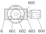
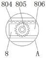
In order to achieve the purpose, the invention provides the following technical scheme: an improved electric rotary automatic car loader comprises a front conveying frame, a lengthened conveying frame, a bottom plate and a main conveying frame, wherein wheels are installed at the middle position of the bottom plate bottom end, a rotary structure is installed on one side of each wheel, the main conveying frame is installed on one side of the bottom plate, an extension structure is installed on one side of the top end of the bottom plate and comprises an extension plate, a protection plate, a base, rack rods, rotary gears and an extension table, the base is installed on one side of the top end of the bottom plate, the protection plate is installed on one side of the top end of the base, the extension plate is installed on one side inside the protection plate, the rack rods are installed at the two ends inside the base, an extension table is installed at one end of each rack rod, the rotary gears are installed on one side of the outer surface of the extension table, the front conveying frame is installed on one side of one end of the extension structure, a hydraulic telescopic rod is installed on one side of the bottom end of the lengthened conveying frame, a control box is installed on the other side of the top end of the bottom plate, and a heat dissipation structure is installed at the bottom end of the outer wall of the control box.
Preferably, revolution mechanic includes master gear, pinion, transmission platform and driving motor, the transmission platform is installed in one side of wheel, driving motor is installed to the one end of transmission platform outer wall, the master gear is installed on the top of transmission platform, the internally mounted of master gear has the pinion, the top of master gear and the bottom fixed connection of bottom plate.
Preferably, the inner diameter of the main gear is larger than the outer diameter of the pinion gear, and the pinion gear is connected with the main gear through a connecting gear.
Preferably, the rack rods are arranged in two groups in total, and the rack rods are symmetrically distributed on the horizontal central axis of the base.
Preferably, the heat radiation structure includes fan, cooling tube and radiating groove, the radiating groove is installed in the bottom of control box outer wall, the surface mounting of radiating groove has the fan, the cooling tube is installed to the one end of fan.
Preferably, the cooling pipes are welded into a whole on the inner side wall of the heat dissipation groove, and are distributed in a snake shape.
Compared with the prior art, the invention has the beneficial effects that: the improved electric rotating automatic car loader not only realizes convenient expansion, but also realizes convenient rotation and convenient heat dissipation;
(1) by arranging the expansion structure, when the device is used, in order to prevent the inconvenience caused by insufficient space of the base, the rotary gear can be directly rotated, so that the rotary gear drives the expansion platform to move left and right on the rack rod, and the expansion plate on the expansion platform is expanded outwards on the protection plate together with the rack rod, so that the use area of the base is increased, and the device is more convenient to operate;
(2) by arranging the rotating structure, when the device is used, in order to increase the used angle of the device, an external power supply of the driving motor can be directly connected, so that the driving motor drives the pinion to rotate through the transmission table, and the pinion drives the main gear to rotate, thereby realizing the adjustment of the angle of the device and increasing the used area of the device;
(3) through being provided with heat radiation structure, when the device is at the in-process that uses, the last control box of the device can control it to can produce a large amount of heats in the inside of control box, at this moment, in order to increase the life of control box, can the direct start fan, make the fan blow the inside of control box with external wind from the radiating groove in, and wind when the inside of entering control box, can pass through the cooling tube, thereby can be quick cool down to wind, make the effect of its cooling better.
Drawings
FIG. 1 is a schematic front sectional view of the present invention;
FIG. 2 is a schematic front view of a heat dissipation structure according to the present invention;
FIG. 3 is a schematic top view of the rotating structure of the present invention;
fig. 4 is an enlarged schematic view of a portion a in fig. 1 according to the present invention.
In the figure: 1. a front carriage; 2. lengthening the conveying frame; 3. a hydraulic telescopic rod; 4. a base plate; 5. a wheel; 6. a rotating structure; 601. a main gear; 602. a pinion gear; 603. a transmission table; 604. a drive motor; 605. a connecting gear; 7. a main conveying frame; 8. an expanded structure; 801. an expansion board; 802. a protection plate; 803. a base; 804. a rack bar; 805. a rotating gear; 806. an extension table; 9. a control box; 10. a heat dissipation structure; 1001. a fan; 1002. a cooling tube; 1003. a heat dissipation groove.
Detailed Description
The technical solutions in the embodiments of the present invention will be clearly and completely described below with reference to the drawings in the embodiments of the present invention, and it is obvious that the described embodiments are only a part of the embodiments of the present invention, and not all of the embodiments. All other embodiments, which can be derived by a person skilled in the art from the embodiments given herein without making any creative effort, shall fall within the protection scope of the present invention.
Referring to fig. 1-4, an embodiment of the present invention is shown: an improved electric rotary automatic car loader comprises a front conveying frame 1, a lengthened conveying frame 2, a bottom plate 4 and a main conveying frame 7, wherein a wheel 5 is installed at the middle position of the bottom end of the bottom plate 4, a rotary structure 6 is installed on one side of the wheel 5, the rotary structure 6 comprises a main gear 601, a secondary gear 602, a transmission table 603 and a driving motor 604, the transmission table 603 is installed on one side of the wheel 5, the driving motor 604 is installed at one end of the outer wall of the transmission table 603, the main gear 601 is installed at the top end of the transmission table 603, the secondary gear 602 is installed inside the main gear 601, the top end of the main gear 601 is fixedly connected with the bottom end of the bottom plate 4, the inner diameter of the main gear 601 is larger than the outer diameter of the secondary gear 602, and the secondary gear 602 is connected with;
specifically, as shown in fig. 1, 3 and 4, when the mechanism is used, firstly, in order to increase the used angle of the device during use, an external power supply of a driving motor 604 can be directly connected, so that the driving motor 604 drives a pinion 602 to rotate through a transmission table 603, the pinion 602 drives a main gear 601 to rotate, so that the bottom plate 4 horizontally rotates, and thus the horizontal angle of the lengthened conveying frame 2 is adjusted, and the used area of the lengthened conveying frame is increased;
the main conveying frame 7 is installed on one side of the bottom plate 4, the extension structure 8 is installed on one side of the top end of the bottom plate 4, the extension structure 8 comprises an extension plate 801, a protection plate 802, a base 803, rack rods 804, rotary gears 805 and extension platforms 806, the base 803 is installed on one side of the top end of the bottom plate 4, the protection plate 802 is installed on one side of the top end of the base 803, the extension plate 801 is installed on one side of the inside of the protection plate 802, the rack rods 804 are installed at two ends of the inside of the base 803, the extension platforms 806 are installed at one end of the rack rods 804, the rotary gears 805 are installed on one side of the outer surface of the extension platforms 806, the rack rods 804 are totally provided in two groups;
specifically, as shown in fig. 1 and 4, when the mechanism is used, firstly, in order to prevent the base 803 from being inconvenient to use due to insufficient space during the use of the device, the rotating gear 805 can be directly rotated, so that the rotating gear 805 drives the expansion platform 806 to move left and right on the rack bar 804, and the expansion plate 801 is expanded on the protection plate 802, thereby increasing the use area of the base 803 and facilitating the operation;
one side of one end of the expansion structure 8 is provided with a front conveying frame 1, the bottom end of the front conveying frame 1 is provided with a lengthened conveying frame 2, one side of the bottom end of the lengthened conveying frame 2 is provided with a hydraulic telescopic rod 3, the other side of the top end of the bottom plate 4 is provided with a control box 9, the bottom end of the outer wall of the control box 9 is provided with a heat dissipation structure 10, the heat dissipation structure 10 comprises a fan 1001, a cooling pipe 1002 and a heat dissipation groove 1003, the heat dissipation groove 1003 is arranged at the bottom end of the outer wall of the control box 9, the outer surface of the heat dissipation groove 1003 is provided with the fan 1001, one end of the fan 1001 is provided with the cooling pipe 1002, the cooling pipe 1002 is in a welding;
specifically, as shown in fig. 1 and fig. 2, when the mechanism is used, firstly, when the device is in use, the control box 9 on the device can control the device, so that a large amount of heat can be generated inside the control box 9, at this time, in order to increase the service life of the control box 9, the fan 1001 can be directly started, so that the fan 1001 blows outside wind from the heat dissipation groove 1003 to the inside of the control box 9, and when the wind enters the inside of the control box 9, the wind passes through the cooling pipe 1002, so that the wind can be rapidly cooled, and the cooling effect is better.
The working principle is as follows: when the device is used, firstly, in order to prevent the inconvenience caused by insufficient space of the base 803 in the using process of the device, the rotating gear 805 can be directly rotated, so that the rotating gear 805 drives the expansion platform 806 to move left and right on the rack bar 804, and the expansion plate 801 is expanded on the protection plate 802, thereby increasing the using area of the base 803 and facilitating the operation.
Then, when the device is in use, in order to increase the used angle, an external power supply of the driving motor 604 can be directly connected, so that the driving motor 604 drives the pinion 602 to rotate through the transmission table 603, the pinion 602 drives the main gear 601 to rotate, and the bottom plate 4 horizontally rotates, thereby adjusting the horizontal angle of the lengthened conveying frame 2 and increasing the used area of the lengthened conveying frame.
Finally, when the device is in the in-process of using, control box 9 on the device can control it to can produce a large amount of heats in control box 9's inside, at this moment, in order to increase control box 9's life, can directly start fan 1001, make fan 1001 blow outside wind to control box 9's inside from radiating groove 1003, and wind when the inside of entering control box 9, can pass through cooling tube 1002, thereby can be quick cool down to wind, make its effect of cooling better.
It will be evident to those skilled in the art that the invention is not limited to the details of the foregoing illustrative embodiments, and that the present invention may be embodied in other specific forms without departing from the spirit or essential attributes thereof. The present embodiments are therefore to be considered in all respects as illustrative and not restrictive, the scope of the invention being indicated by the appended claims rather than by the foregoing description, and all changes which come within the meaning and range of equivalency of the claims are therefore intended to be embraced therein. Any reference sign in a claim should not be construed as limiting the claim concerned.
Claims (6)
1. The utility model provides an electronic rotatory auto-loader of improved generation, includes preceding carriage (1), extension carriage (2), bottom plate (4) and main carriage (7), its characterized in that: wheel (5) are installed at the intermediate position department of bottom plate (4) bottom, rotating-structure (6) are installed to one side of wheel (5), main carriage (7) are installed to one side of bottom plate (4), extending structure (8) are installed to one side on bottom plate (4) top, extending structure (8) include expansion board (801), guard plate (802), base (803), rack bar (804), swing pinion (805) and extension platform (806), base (803) are installed in one side on bottom plate (4) top, guard plate (802) are installed to one side on base (803) top, extension board (801) are installed to one side inside of guard plate (802), rack bar (804) are all installed at the both ends inside base (803), extension platform (806) are installed to the one end of rack bar (804), swing pinion (805) are installed to one side of extension platform (806) surface, conveyer (1) before installing in one side of extension structure (8) one end, extension conveyer (2) are installed to the bottom of preceding conveyer (1), hydraulic telescoping rod (3) are installed to one side of extension conveyer (2) bottom, control box (9) are installed to the opposite side on bottom plate (4) top, heat radiation structure (10) are installed to the bottom of control box (9) outer wall.
2. The improved electric rotary automatic car loader of claim 1, wherein: revolution mechanic (6) include master gear (601), pinion (602), transmission platform (603) and driving motor (604), install in one side of wheel (5) transmission platform (603), driving motor (604) are installed to the one end of transmission platform (603) outer wall, master gear (601) are installed on the top of transmission platform (603), the internally mounted of master gear (601) has pinion (602), the top of master gear (601) and the bottom fixed connection of bottom plate (4).
3. The improved electric rotary automatic car loader of claim 2, wherein: the inner diameter of the main gear (601) is larger than the outer diameter of the pinion (602), and the pinion (602) is connected with the main gear (601) through a connecting gear (605).
4. The improved electric rotary automatic car loader of claim 1, wherein: the rack rods (804) are arranged in two groups, and the rack rods (804) are symmetrically distributed on the horizontal central axis of the base (803).
5. The improved electric rotary automatic car loader of claim 1, wherein: the heat dissipation structure (10) comprises a fan (1001), a cooling pipe (1002) and a heat dissipation groove (1003), wherein the heat dissipation groove (1003) is installed at the bottom end of the outer wall of the control box (9), the fan (1001) is installed on the outer surface of the heat dissipation groove (1003), and the cooling pipe (1002) is installed at one end of the fan (1001).
6. The improved electric rotary automatic car loader of claim 5, wherein: the cooling pipes (1002) are in a welding integrated structure on the inner side wall of the heat dissipation groove (1003), and the cooling pipes (1002) are distributed in a snake shape.
Priority Applications (1)
| Application Number | Priority Date | Filing Date | Title |
|---|---|---|---|
| CN202011266009.9A CN112061717B (en) | 2020-11-13 | 2020-11-13 | Improved electric rotating automatic car loader |
Applications Claiming Priority (1)
| Application Number | Priority Date | Filing Date | Title |
|---|---|---|---|
| CN202011266009.9A CN112061717B (en) | 2020-11-13 | 2020-11-13 | Improved electric rotating automatic car loader |
Publications (2)
| Publication Number | Publication Date |
|---|---|
| CN112061717A CN112061717A (en) | 2020-12-11 |
| CN112061717B true CN112061717B (en) | 2021-01-12 |
Family
ID=73655016
Family Applications (1)
| Application Number | Title | Priority Date | Filing Date |
|---|---|---|---|
| CN202011266009.9A Active CN112061717B (en) | 2020-11-13 | 2020-11-13 | Improved electric rotating automatic car loader |
Country Status (1)
| Country | Link |
|---|---|
| CN (1) | CN112061717B (en) |
Families Citing this family (2)
| Publication number | Priority date | Publication date | Assignee | Title |
|---|---|---|---|---|
| CN113264338B (en) * | 2021-07-16 | 2021-09-24 | 江苏萨通智能物流装备有限公司 | Movable belt conveyor |
| CN113955414B (en) * | 2021-11-09 | 2023-10-03 | 南京金牛湖科技产业园投资发展有限公司 | Angle-adjustable silkworm feeding machine |
Family Cites Families (8)
| Publication number | Priority date | Publication date | Assignee | Title |
|---|---|---|---|---|
| CN2136224Y (en) * | 1992-09-12 | 1993-06-16 | 沃勤生 | Multifunctional belt conveyer |
| US7451866B2 (en) * | 2006-06-08 | 2008-11-18 | Nmc-Wollard, Inc. | Conveying device |
| CN202449516U (en) * | 2012-01-12 | 2012-09-26 | 山东汇科通用机械有限公司 | Mobile belt conveyor of novel loading and unloading vehicle |
| CN204150630U (en) * | 2014-10-11 | 2015-02-11 | 衡水金太阳输送机械工程有限公司 | A kind of frame of belt conveyer |
| CN204673575U (en) * | 2015-05-29 | 2015-09-30 | 江西洪都航空工业集团有限责任公司 | A kind of flexible auxiliary working platform |
| JP6141469B2 (en) * | 2016-02-09 | 2017-06-07 | 三菱重工交通機器エンジニアリング株式会社 | Two-stage telescopic home door device |
| CN205661984U (en) * | 2016-04-22 | 2016-10-26 | 盐城市远南机械有限公司 | Multi -functional steering conveyor of electric telescopic type |
| CN208265096U (en) * | 2018-03-23 | 2018-12-21 | 南安市创培电子科技有限公司 | A kind of Intelligent logistics warehouse landing platform |
-
2020
- 2020-11-13 CN CN202011266009.9A patent/CN112061717B/en active Active
Also Published As
| Publication number | Publication date |
|---|---|
| CN112061717A (en) | 2020-12-11 |
Similar Documents
| Publication | Publication Date | Title |
|---|---|---|
| CN112061717B (en) | Improved electric rotating automatic car loader | |
| CN211592285U (en) | Fill electric pile that possesses alarming function | |
| CN212503349U (en) | U-shaped sliding contact wire winding device | |
| CN210605572U (en) | High-efficient radiating computer mainframe | |
| CN112952576B (en) | Intelligent power distribution cabinet based on electric power of Internet of things | |
| CN114141474A (en) | Electric power high voltage transmission equipment | |
| CN113365158B (en) | Novel 5G base station | |
| CN210771828U (en) | Solar street lamp of environmental protection heat dissipation type | |
| CN211502599U (en) | LED street lamp with good heat dissipation performance | |
| CN211670827U (en) | Solar panel rotating device | |
| CN112045416A (en) | A centrifugal fan placer that is used for quick installation on assembly line frame | |
| CN214660631U (en) | Clean energy power generation device for tunnel | |
| CN216680992U (en) | Large-scale fan rotor restores and uses bearing device | |
| CN207764730U (en) | A kind of heat sinking dustproof case | |
| CN213705219U (en) | New energy automobile is with filling electric pile fast | |
| CN218269648U (en) | Waste energy recovery device of air source heat pump | |
| CN113183735B (en) | Installation fixing device for electric tricycle motor | |
| CN217300785U (en) | Cooling device for wind driven generator | |
| CN211875886U (en) | Solar street lamp of environmental protection heat dissipation type | |
| CN213207019U (en) | Novel animation show LED two-sided screen | |
| CN212225438U (en) | Wind power generation device | |
| CN220647942U (en) | Rotary lighting structure of solar street lamp | |
| CN111313811A (en) | Sun-tracking rotating device for solar power generation | |
| CN207572800U (en) | A kind of traffic signals collection device power distribution cabinet shell | |
| CN213044006U (en) | Heat dissipation device for flat-plate type switching power supply |
Legal Events
| Date | Code | Title | Description |
|---|---|---|---|
| PB01 | Publication | ||
| PB01 | Publication | ||
| SE01 | Entry into force of request for substantive examination | ||
| SE01 | Entry into force of request for substantive examination | ||
| GR01 | Patent grant | ||
| GR01 | Patent grant |