CN112059292A - Aluminium alloy centre gripping cutting device - Google Patents
Aluminium alloy centre gripping cutting device Download PDFInfo
- Publication number
- CN112059292A CN112059292A CN202011063154.7A CN202011063154A CN112059292A CN 112059292 A CN112059292 A CN 112059292A CN 202011063154 A CN202011063154 A CN 202011063154A CN 112059292 A CN112059292 A CN 112059292A
- Authority
- CN
- China
- Prior art keywords
- screw rod
- sliding table
- rod sliding
- bearing seat
- cutting
- Prior art date
- Legal status (The legal status is an assumption and is not a legal conclusion. Google has not performed a legal analysis and makes no representation as to the accuracy of the status listed.)
- Pending
Links
Images


Classifications
-
- B—PERFORMING OPERATIONS; TRANSPORTING
- B23—MACHINE TOOLS; METAL-WORKING NOT OTHERWISE PROVIDED FOR
- B23D—PLANING; SLOTTING; SHEARING; BROACHING; SAWING; FILING; SCRAPING; LIKE OPERATIONS FOR WORKING METAL BY REMOVING MATERIAL, NOT OTHERWISE PROVIDED FOR
- B23D47/00—Sawing machines or sawing devices working with circular saw blades, characterised only by constructional features of particular parts
- B23D47/08—Sawing machines or sawing devices working with circular saw blades, characterised only by constructional features of particular parts of devices for bringing the circular saw blade to the workpiece or removing same therefrom
-
- B—PERFORMING OPERATIONS; TRANSPORTING
- B23—MACHINE TOOLS; METAL-WORKING NOT OTHERWISE PROVIDED FOR
- B23D—PLANING; SLOTTING; SHEARING; BROACHING; SAWING; FILING; SCRAPING; LIKE OPERATIONS FOR WORKING METAL BY REMOVING MATERIAL, NOT OTHERWISE PROVIDED FOR
- B23D47/00—Sawing machines or sawing devices working with circular saw blades, characterised only by constructional features of particular parts
- B23D47/02—Sawing machines or sawing devices working with circular saw blades, characterised only by constructional features of particular parts of frames; of guiding arrangements for work-table or saw-carrier
Abstract
The invention relates to the technical field of aluminum profile cutting, in particular to an aluminum profile clamping and cutting device which comprises a rectangular frame base, wherein a portal frame is vertically connected onto the rectangular frame base, an X-axis screw rod sliding table is arranged below the portal frame and on the end surface of the rectangular frame base, an aluminum profile positioning jig is connected onto the X-axis screw rod sliding table, and a PLC (programmable logic controller) is arranged on one side of the X-axis screw rod sliding table and on the end surface of the rectangular frame base, the cutting structure is combined with an X, Y, Z axial screw rod sliding table and a worm gear structure, so that the cutting structure can be axially cut at X, Y, Z, the cutting structure can be adjusted at different angles, the multi-directional and multi-angle cutting of a plate is realized, the position of the plate is not required to be continuously adjusted, and the plate is continuously clamped, the processing time is greatly saved, the working efficiency is improved, and the service performance of the cutting device is improved.
Description
Technical Field
The invention relates to the technical field of aluminum profile cutting, in particular to an aluminum profile clamping and cutting device.
Background
The cutting method of the existing cutting device for the aluminum profile is single, the position of the plate needs to be adjusted for multiple times, the plate is tightened, finally, the cutting device is used for cutting and processing for multiple times, the plates with different sizes and different shapes are cut and processed, the position of the plate is continuously adjusted and the plate is continuously clamped in the process, a large amount of time needs to be wasted, and the problem of low working efficiency is caused
Disclosure of Invention
The invention aims to provide an aluminum profile clamping and cutting device to solve the problems in the background technology.
In order to achieve the purpose, the invention provides the following technical scheme:
an aluminum profile clamping and cutting device comprises a rectangular frame base, wherein a portal frame is vertically connected onto the rectangular frame base, an X-axis screw rod sliding table is arranged below the portal frame and on the end face of the rectangular frame base, an aluminum profile positioning jig is connected onto the X-axis screw rod sliding table, a PLC (programmable logic controller) is arranged on one side of the X-axis screw rod sliding table and on the end face of the rectangular frame base, a Y-axis screw rod sliding table is arranged on the front face of the portal frame, a Y-axis moving table is connected onto the Y-axis screw rod sliding table, a Z-axis screw rod sliding table is connected onto the front face of the Y-axis moving table, a Z-axis moving table is connected onto the Z-axis screw rod sliding table, a driving motor is arranged on the front face of the Z-axis moving table and above the aluminum profile positioning jig, a driving shaft of the driving motor is connected onto a speed, the rotating shaft of the speed reducer is connected with one end of a worm through a coupling, the left end and the right end of the worm are respectively sleeved with a left bearing seat and a right bearing seat, the left bearing seat and the right bearing seat are respectively embedded on the opposite side walls of the transmission case, the transmission case is connected on the Z-axis moving platform, a transmission gear is connected on the worm and positioned in the transmission case, a rotating rod is arranged at the center of the transmission gear, the upper end and the lower end of the rotating rod are respectively connected with the inner parts of an upper bearing seat and a lower bearing seat which are respectively embedded on the opposite side walls of the transmission case, the bottom of the rotating rod penetrates through the lower bearing seat and extends to the outside of the transmission case to be connected to the inside of the mounting seat, the mount pad fixed connection is on cutting motor, cutting motor's drive shaft is connected with cutting blade, on the cutting motor and be located and be provided with the protection casing between cutting motor and the cutting blade.
Preferably, the X-axis screw rod sliding table, the Y-axis screw rod sliding table and the Z-axis screw rod sliding table are electric screw rod sliding tables and are respectively and electrically connected to the PLC through leads.
Preferably, the driving motor and the cutting motor are respectively and electrically connected to the PLC through wires.
Preferably, the left end and the right end of the worm are respectively connected with the left bearing seat and the right bearing seat in a rotating manner.
Preferably, the worm and the transmission gear are connected in a meshing manner and form a worm gear structure.
Preferably, the upper end and the lower end of the rotating rod are respectively connected with the upper bearing seat and the lower bearing seat in a rotating manner.
Preferably, the worm and the rotating rod are perpendicular to each other.
Compared with the prior art, the invention has the beneficial effects that:
1. in the invention, the cutting structure is combined with the X, Y, Z axial lead screw sliding table and the worm gear structure, so that the cutting structure can be axially cut at X, Y, Z, the cutting structure can be adjusted at different angles, and the multi-direction and multi-angle cutting of the plate is further realized, the problems that the plate in the existing aluminum profile is cut in a reciprocating way in a single and reverse direction, the plate is cut into a plurality of single and smaller plates, the cutting method is single, the position of the plate is required to be adjusted for many times according to the working requirement and is tightened, finally the plate with different sizes and different shapes is required to be cut and processed by cutting the plate with a cutting device for many times, the position of the plate is not required to be adjusted continuously and the plate is clamped continuously are solved, the processing time is greatly saved, the working efficiency is improved, and the service performance of the cutting device is improved.
Drawings
FIG. 1 is a schematic structural view of the present invention;
FIG. 2 is a schematic structural view of a part of the present invention;
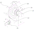
FIG. 3 is a partially enlarged schematic view of the present invention;
FIG. 4 is a schematic illustration of the partially exploded structure of FIG. 3 in accordance with the present invention;
FIG. 5 is a schematic view of a partial cross-sectional structure of the transmission case of the present invention;
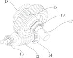
FIG. 6 is a schematic view of a portion of the present invention;
FIG. 7 is a schematic view of a portion of the structure of the present invention.
In the figure: the device comprises a 1-rectangular frame base, a 2-portal frame, a 3-X shaft screw rod sliding table, a 4-aluminum profile positioning jig, a 5-PLC controller, a 6-Y shaft screw rod sliding table, a 7-Y shaft moving table, an 8-Z shaft screw rod sliding table, a 9-Z shaft moving table, a 10-driving motor, a 11-speed reducer, a 12-worm, a 13-left bearing seat, a 14-right bearing seat, a 15-transmission box, a 16-transmission gear, a 17-rotating rod, an 18-upper bearing seat, a 19-lower bearing seat, a 20-mounting seat, a 21-cutting motor, a 22-cutting blade and a 23-protective cover.
Detailed Description
The technical solutions in the embodiments of the present invention will be clearly and completely described below with reference to the drawings in the embodiments of the present invention, and it is obvious that the described embodiments are only a part of the embodiments of the present invention, and not all embodiments, and all other embodiments obtained by a person of ordinary skill in the art without creative efforts based on the embodiments of the present invention belong to the protection scope of the present invention.
Referring to fig. 1-7, the present invention provides a technical solution:
an aluminum profile clamping and cutting device comprises a rectangular frame base 1, a portal frame 2 is vertically connected onto the rectangular frame base 1, an X-axis screw rod sliding table 3 is arranged below the portal frame 2 and on the end face of the rectangular frame base 1, an aluminum profile positioning jig 4 is connected onto the X-axis screw rod sliding table 3, a PLC (programmable logic controller) 5 is arranged on one side of the X-axis screw rod sliding table 3 and on the end face of the rectangular frame base 1, a Y-axis screw rod sliding table 6 is arranged on the front face of the portal frame 2, a Y-axis moving table 7 is connected onto the Y-axis screw rod sliding table 6, a Z-axis screw rod sliding table 8 is connected onto the front face of the Y-axis moving table 7, a Z-axis moving table 9 is connected onto the Z-axis screw rod sliding table 8, a driving motor 10 is arranged on the front face of the Z-axis moving table 9 and above the aluminum profile positioning jig 4, a driving shaft of the driving, the rotating shaft of the speed reducer 11 is connected to one end of a worm 12 through a coupling, a left bearing seat 13 and a right bearing seat 14 are respectively sleeved at the left end and the right end of the worm 12, the left bearing seat 13 and the right bearing seat 14 are respectively embedded on the opposite side walls of a transmission case 15, the transmission case 15 is connected to a Z-axis mobile station 9, a transmission gear 16 is connected to the worm 12 and positioned inside the transmission case 15, a rotating rod 17 is arranged at the center of the transmission gear 16, the upper end and the lower end of the rotating rod 17 are respectively connected to the inside of an upper bearing seat 18 and a lower bearing seat 19, the upper bearing seat 18 and the lower bearing seat 19 are respectively embedded on the opposite side walls of the transmission case 15, the bottom of the rotating rod 17 penetrates through the lower bearing seat 19 and extends to the outside of the transmission case 15 to be connected to the inside of a mounting seat, a guard 23 is provided on the cutting motor 21 and between the cutting motor 21 and the cutting blade 22.
The working process of the invention is as follows: when the aluminum profile positioning device is used, a plate is placed on the aluminum profile positioning jig 4 for positioning, at the moment, the equipment is electrified under the action that the X-axis screw rod sliding table 3, the Y-axis screw rod sliding table 6 and the Z-axis screw rod sliding table 8 are electric screw rod sliding tables and are respectively and electrically connected to the PLC controller 5 through leads and the driving motor 10 and the cutting motor 21 are respectively and electrically connected to the PLC controller 5 through leads, at the moment, the PLC controller 5 is operated to control the X-axis screw rod sliding table 3 to move according to working requirements, so that the aluminum profile positioning jig 4 is driven to run in the X-axis direction or the Y-axis screw rod sliding table 6 is driven to run in the Y-axis direction or the Z-axis screw rod sliding table 8 is driven to move, thereby driving the cutting blade structure connected with the Z-axis moving table 9 to run in the Z-axis direction, meanwhile, the PLC controller 5 is operated to start, after the cutting motor 21 is started, the cutting blade 22 is driven to rotate, the sheet is cut, different cutting of the sheet in the X, Y, Z axial direction is achieved, under the action that the upper end and the lower end of the rotating rod 17 are respectively in rotary connection with the upper bearing seat 18 and the lower bearing seat 19, the driving motor 10 is started, the driving motor 10 rotates after being started, the speed reducer 11 is driven to operate, after the speed reducer 11 operates, under the action that the left end and the right end of the worm 12 are respectively in rotary connection with the left bearing seat 13 and the right bearing seat 14, the worm 12 is driven to rotate, after the worm 12 rotates, the transmission gear 16 is driven to rotate under the action that the connecting mode of the worm 12 and the transmission gear 16 is in meshing connection and forms a worm gear structure, and the connecting mode of the upper end and the lower end of the rotating rod 17 are respectively in rotary connection with the upper, the transmission gear 16 rotates to drive the rotating rod 17 to rotate, the rotating rod 17 rotates to drive the cutting blade structure to rotate, so that the angle adjustment of the cutting blade 22 is realized, in the process, the cutting structure is combined with the X, Y, Z axial lead screw sliding table and the worm and gear structure, so that the cutting structure can be axially cut at X, Y, Z, and meanwhile, the cutting structure can be adjusted at different angles, so that the plate can be cut in multiple directions and at multiple angles, the problem that the plate cutting in the existing aluminum profile is the one-way and reverse-direction reciprocating cutting is solved, the plate is cut into a plurality of single small plates, so that the cutting method is single, the cut plates with similar structures need to be adjusted for multiple times according to the working requirements, the positions of the plates are tightened, and finally, the cutting device is used for cutting and processing for multiple times, the problem that plates with different sizes and shapes are required to be cut and processed is solved, so that the positions of the plates do not need to be continuously adjusted and the plates are continuously clamped, the processing time is greatly saved, the working efficiency is improved, and the using performance of the cutting device is improved.
Although embodiments of the present invention have been shown and described, it will be appreciated by those skilled in the art that changes, modifications, substitutions and alterations can be made in these embodiments without departing from the principles and spirit of the invention, the scope of which is defined in the appended claims and their equivalents.
Claims (7)
1. The utility model provides an aluminium alloy centre gripping cutting device, includes the rectangular frame base, its characterized in that: the automatic feeding device is characterized in that a portal frame is vertically connected onto the rectangular frame base, an X-axis screw rod sliding table is arranged below the portal frame and on the end face of the rectangular frame base, an aluminum profile positioning jig is connected onto the X-axis screw rod sliding table, a PLC (programmable logic controller) is arranged on one side of the X-axis screw rod sliding table and on the end face of the rectangular frame base, a Y-axis screw rod sliding table is arranged on the front face of the portal frame, a Y-axis moving table is connected onto the Y-axis screw rod sliding table, a Z-axis screw rod sliding table is connected onto the front face of the Y-axis moving table, a Z-axis moving table is connected onto the Z-axis screw rod sliding table, a driving motor is arranged on the front face of the Z-axis moving table and above the aluminum profile positioning jig, a driving shaft of the driving motor is connected onto a speed reducer, the speed reducer is connected, the left end and the right end of the worm are respectively sleeved with a left bearing seat and a right bearing seat which are respectively embedded on the opposite side walls of the transmission case, the transmission case is connected on the Z-axis moving platform, the worm is connected with a transmission gear inside the transmission case, a rotating rod is arranged at the center of the transmission gear, the upper end and the lower end of the rotating rod are respectively connected with the inner parts of the upper bearing seat and the lower bearing seat, the upper bearing seat and the lower bearing seat are respectively embedded on the opposite side walls of the transmission case, the bottom of the rotating rod penetrates through the lower bearing seat and extends to the outside of the transmission case to be connected with the inside of the mounting seat, the mount pad fixed connection is on cutting motor, cutting motor's drive shaft is connected with cutting blade, on the cutting motor and be located and be provided with the protection casing between cutting motor and the cutting blade.
2. The aluminum profile clamping and cutting device as claimed in claim 1, characterized in that: and the X-axis screw rod sliding table, the Y-axis screw rod sliding table and the Z-axis screw rod sliding table are electric screw rod sliding tables and are respectively electrically connected to the PLC through leads.
3. The aluminum profile clamping and cutting device as claimed in claim 1, characterized in that: the driving motor and the cutting motor are respectively and electrically connected to the PLC through wires.
4. The aluminum profile clamping and cutting device as claimed in claim 1, characterized in that: the left end and the right end of the worm are respectively connected with the left bearing seat and the right bearing seat in a rotating mode.
5. The aluminum profile clamping and cutting device as claimed in claim 1, characterized in that: the worm and the transmission gear are connected in a meshing manner to form a worm and gear structure.
6. The aluminum profile clamping and cutting device as claimed in claim 1, characterized in that: the upper end and the lower end of the rotating rod are respectively connected with the upper bearing seat and the lower bearing seat in a rotating mode.
7. The aluminum profile clamping and cutting device as claimed in claim 1, characterized in that: the worm is perpendicular to the rotating rod.
Priority Applications (1)
| Application Number | Priority Date | Filing Date | Title |
|---|---|---|---|
| CN202011063154.7A CN112059292A (en) | 2020-09-30 | 2020-09-30 | Aluminium alloy centre gripping cutting device |
Applications Claiming Priority (1)
| Application Number | Priority Date | Filing Date | Title |
|---|---|---|---|
| CN202011063154.7A CN112059292A (en) | 2020-09-30 | 2020-09-30 | Aluminium alloy centre gripping cutting device |
Publications (1)
| Publication Number | Publication Date |
|---|---|
| CN112059292A true CN112059292A (en) | 2020-12-11 |
Family
ID=73683300
Family Applications (1)
| Application Number | Title | Priority Date | Filing Date |
|---|---|---|---|
| CN202011063154.7A Pending CN112059292A (en) | 2020-09-30 | 2020-09-30 | Aluminium alloy centre gripping cutting device |
Country Status (1)
| Country | Link |
|---|---|
| CN (1) | CN112059292A (en) |
Cited By (7)
| Publication number | Priority date | Publication date | Assignee | Title |
|---|---|---|---|---|
| CN112719436A (en) * | 2020-12-17 | 2021-04-30 | 常熟建华模具科技股份有限公司 | High-efficiency cutting device for casting head of glass mold |
| CN112828919A (en) * | 2021-01-05 | 2021-05-25 | 赵淑英 | Five-axis manipulator for injection molding machine |
| CN114918491A (en) * | 2022-07-22 | 2022-08-19 | 山西天宝集团有限公司 | Steel cutting device and method for offshore wind power flange |
| CN115106552A (en) * | 2022-06-23 | 2022-09-27 | 驰逸自动化科技(苏州)有限公司 | Precision machining equipment for hard turning machine special-shaped alloy and working method thereof |
| CN115178792A (en) * | 2022-09-14 | 2022-10-14 | 石家庄旭东机械制造有限公司 | Novel auger blade cutting machine |
| CN115416106A (en) * | 2022-10-11 | 2022-12-02 | 衡东振好木制品有限公司 | Wood cutting device convenient to fixed timber |
| CN116237587A (en) * | 2023-05-09 | 2023-06-09 | 海睿斯(江苏)机械科技有限公司 | Triaxial servo numerical control steel plate sawing machine |
-
2020
- 2020-09-30 CN CN202011063154.7A patent/CN112059292A/en active Pending
Cited By (10)
| Publication number | Priority date | Publication date | Assignee | Title |
|---|---|---|---|---|
| CN112719436A (en) * | 2020-12-17 | 2021-04-30 | 常熟建华模具科技股份有限公司 | High-efficiency cutting device for casting head of glass mold |
| CN112828919A (en) * | 2021-01-05 | 2021-05-25 | 赵淑英 | Five-axis manipulator for injection molding machine |
| CN115106552A (en) * | 2022-06-23 | 2022-09-27 | 驰逸自动化科技(苏州)有限公司 | Precision machining equipment for hard turning machine special-shaped alloy and working method thereof |
| CN114918491A (en) * | 2022-07-22 | 2022-08-19 | 山西天宝集团有限公司 | Steel cutting device and method for offshore wind power flange |
| CN114918491B (en) * | 2022-07-22 | 2022-11-04 | 山西天宝集团有限公司 | Steel cutting device and method for offshore wind power flange |
| CN115178792A (en) * | 2022-09-14 | 2022-10-14 | 石家庄旭东机械制造有限公司 | Novel auger blade cutting machine |
| CN115178792B (en) * | 2022-09-14 | 2022-12-20 | 石家庄旭东机械制造有限公司 | Novel auger blade cutting machine |
| CN115416106A (en) * | 2022-10-11 | 2022-12-02 | 衡东振好木制品有限公司 | Wood cutting device convenient to fixed timber |
| CN116237587A (en) * | 2023-05-09 | 2023-06-09 | 海睿斯(江苏)机械科技有限公司 | Triaxial servo numerical control steel plate sawing machine |
| CN116237587B (en) * | 2023-05-09 | 2023-07-14 | 海睿斯(江苏)机械科技有限公司 | Triaxial servo numerical control steel plate sawing machine |
Similar Documents
| Publication | Publication Date | Title |
|---|---|---|
| CN112059292A (en) | Aluminium alloy centre gripping cutting device | |
| CN212599386U (en) | Aluminium alloy centre gripping cutting device | |
| WO2017197770A1 (en) | Intelligent wire sheave trimming machine | |
| CN206153652U (en) | Quick plate shearing machine of punch press repacking | |
| CN100340381C (en) | Machine for sawing corner of plate | |
| WO2017197775A1 (en) | Intelligent track-type linear terminal crimping machine | |
| CN209532249U (en) | A kind of plate cutting machine of auto parts and components production | |
| CN106042039B (en) | A kind of automatic bubble cutting machine | |
| CN108581034A (en) | A kind of pipe fitting cutter device with clamping function | |
| CN209919604U (en) | Faucet surface machining equipment | |
| CN105149683B (en) | A kind of numerical control aluminum section saw cutting machine | |
| CN217432847U (en) | Multifunctional metal plate machining center positioning device | |
| CN215942364U (en) | High-efficient grinding device is used in glassware production | |
| CN213257222U (en) | Numerical control machine tool for machining gearbox shell | |
| CN214187535U (en) | Cell-phone accessory cutting device | |
| CN110666545B (en) | Axial cutting device of nonrust steel pipe | |
| CN209649527U (en) | A kind of Multipurpose single-boom hydraulic press | |
| CN209699293U (en) | A kind of transverse direction sawing apparatus and timber dapper | |
| CN207343912U (en) | A kind of aluminium section bar trimming device | |
| CN219335474U (en) | Bending device convenient to adjust | |
| CN217316825U (en) | High-efficient rigging equipment is used in servo alternating current motor processing | |
| CN220127482U (en) | Wire harness efficient cutting device for wire harness assembly | |
| CN216576738U (en) | High-rise security is aluminum mould board cutting process device for house | |
| CN220805218U (en) | Centrifugal fan air outlet punching press anchor clamps | |
| CN213350318U (en) | Bending equipment |
Legal Events
| Date | Code | Title | Description |
|---|---|---|---|
| PB01 | Publication | ||
| PB01 | Publication | ||
| SE01 | Entry into force of request for substantive examination | ||
| SE01 | Entry into force of request for substantive examination |