CN112040887A - Surgical clip - Google Patents
Surgical clip Download PDFInfo
- Publication number
- CN112040887A CN112040887A CN201980014376.9A CN201980014376A CN112040887A CN 112040887 A CN112040887 A CN 112040887A CN 201980014376 A CN201980014376 A CN 201980014376A CN 112040887 A CN112040887 A CN 112040887A
- Authority
- CN
- China
- Prior art keywords
- clamping
- surgical clip
- helical spring
- winding portion
- winding
- Prior art date
- Legal status (The legal status is an assumption and is not a legal conclusion. Google has not performed a legal analysis and makes no representation as to the accuracy of the status listed.)
- Granted
Links
Images


Classifications
-
- A—HUMAN NECESSITIES
- A61—MEDICAL OR VETERINARY SCIENCE; HYGIENE
- A61B—DIAGNOSIS; SURGERY; IDENTIFICATION
- A61B17/00—Surgical instruments, devices or methods
- A61B17/12—Surgical instruments, devices or methods for ligaturing or otherwise compressing tubular parts of the body, e.g. blood vessels or umbilical cord
- A61B17/122—Clamps or clips, e.g. for the umbilical cord
- A61B17/1227—Spring clips
-
- A—HUMAN NECESSITIES
- A61—MEDICAL OR VETERINARY SCIENCE; HYGIENE
- A61B—DIAGNOSIS; SURGERY; IDENTIFICATION
- A61B17/00—Surgical instruments, devices or methods
- A61B17/12—Surgical instruments, devices or methods for ligaturing or otherwise compressing tubular parts of the body, e.g. blood vessels or umbilical cord
- A61B17/12022—Occluding by internal devices, e.g. balloons or releasable wires
- A61B17/12099—Occluding by internal devices, e.g. balloons or releasable wires characterised by the location of the occluder
- A61B17/12109—Occluding by internal devices, e.g. balloons or releasable wires characterised by the location of the occluder in a blood vessel
- A61B17/12113—Occluding by internal devices, e.g. balloons or releasable wires characterised by the location of the occluder in a blood vessel within an aneurysm
Landscapes
- Health & Medical Sciences (AREA)
- Surgery (AREA)
- Life Sciences & Earth Sciences (AREA)
- Biomedical Technology (AREA)
- Medical Informatics (AREA)
- Vascular Medicine (AREA)
- Reproductive Health (AREA)
- Engineering & Computer Science (AREA)
- Veterinary Medicine (AREA)
- Heart & Thoracic Surgery (AREA)
- Nuclear Medicine, Radiotherapy & Molecular Imaging (AREA)
- Molecular Biology (AREA)
- Animal Behavior & Ethology (AREA)
- General Health & Medical Sciences (AREA)
- Public Health (AREA)
- Neurosurgery (AREA)
- Surgical Instruments (AREA)
Abstract
本发明涉及一种手术夹,所述手术夹包括第一夹持臂、第二夹持臂以及偏压元件,所述第一夹持臂限定第一夹持表面,并且所述第二夹持臂限定第二夹持表面,并且所述偏压元件特别是在预张力下使所述第一夹持表面和所述第二夹持表面在基本位置中保持彼此抵靠。所述第一夹持臂和第二夹持臂能够克服所述偏压元件的作用而相对于彼此枢转,其中,所述偏压元件被形成为螺旋弹簧,所述螺旋弹簧限定了螺旋弹簧纵向轴线并具有第一螺旋弹簧端和第二螺旋弹簧端。所述螺旋弹簧在所述第一螺旋弹簧端和所述第二螺旋弹簧端之间包括至少一个绕组,所述绕组在大于360°的周向角上延伸。所述第一螺旋弹簧端通过第一连接部连接到所述第一夹持臂,其中,所述第二螺旋弹簧端通过第二连接部连接到所述第二夹持臂,并且其中,在所述基本位置中保持彼此抵靠的所述夹持表面限定了夹持平面。为了使手术夹更易于操纵,根据本发明,所述螺旋弹簧的纵向轴线平行于所述夹持平面延伸。
The present invention relates to a surgical clip comprising a first gripping arm, a second gripping arm, and a biasing element, the first gripping arm defining a first gripping surface, and the second gripping The arm defines a second clamping surface, and the biasing element keeps the first clamping surface and the second clamping surface against each other in the basic position, in particular under pretension. The first and second clamping arms are pivotable relative to each other against the action of the biasing element, wherein the biasing element is formed as a coil spring defining a coil spring The longitudinal axis has a first coil spring end and a second coil spring end. The coil spring includes at least one winding between the first coil spring end and the second coil spring end, the winding extending over a circumferential angle greater than 360°. the first coil spring end is connected to the first clamp arm by a first connection, wherein the second coil spring end is connected to the second clamp arm by a second connection, and wherein the The clamping surfaces held against each other in the basic position define a clamping plane. In order to make the surgical clip easier to handle, according to the invention, the longitudinal axis of the helical spring extends parallel to the clamping plane.
Description
技术领域technical field
本发明涉及一种手术夹,该手术夹包括第一夹持臂、第二夹持臂以及偏压元件,所述第一夹持臂限定第一夹持表面,所述第二夹持臂限定第二夹持表面,并且所述偏压元件特别是在偏压下使所述第一夹持表面和所述第二夹持表面在基本位置中保持彼此抵靠,其中,所述第一夹持臂和第二夹持臂能够克服所述偏压元件的作用而相对于彼此枢转,其中,所述偏压元件被构造成螺旋弹簧的形式,所述螺旋弹簧限定了螺旋弹簧纵向轴线并具有第一螺旋弹簧端和第二螺旋弹簧端,其中,所述螺旋弹簧在所述第一螺旋弹簧端和所述第二螺旋弹簧端之间包括至少一个绕组,所述至少一个绕组在大于360°的周向角上延伸,其中,所述第一螺旋弹簧端通过第一连接部连接到所述第一夹持臂,其中,所述第二螺旋弹簧端通过第二连接部连接到所述第二夹持臂,并且其中,在所述基本位置保持彼此抵靠的所述夹持表面限定了夹持平面。The present invention relates to a surgical clip comprising a first gripping arm, a second gripping arm defining a first gripping surface, and a second gripping arm defining a biasing element A second clamping surface, and the biasing element holds the first clamping surface and the second clamping surface against each other in a basic position, in particular under bias, wherein the first clamping The holding arm and the second clamping arm are pivotable relative to each other against the action of the biasing element, wherein the biasing element is configured in the form of a helical spring defining a longitudinal axis of the helical spring and having a first coil spring end and a second coil spring end, wherein the coil spring includes at least one winding between the first coil spring end and the second coil spring end, the at least one winding being greater than 360 °, wherein the first coil spring end is connected to the first clamping arm by a first connection portion, wherein the second coil spring end is connected to the second clamp arm by a second connection portion clamping arms, and wherein the clamping surfaces held against each other in the basic position define a clamping plane.
背景技术Background technique
开篇所述的那种手术夹被用于手术中,特别是用于治疗动脉瘤。使用这种所谓的“动脉瘤夹”,通过夹除两个夹持臂的夹持表面之间的囊,来夹除例如动脉瘤、即中空器官(例如血管)的囊。Surgical clips of the kind described at the outset are used in surgery, especially for the treatment of aneurysms. Using such so-called "aneurysm clips", sacs, such as aneurysms, ie hollow organs, such as blood vessels, are clipped by clipping the sac between the gripping surfaces of the two gripping arms.
在已知的手术夹中,螺旋弹簧通过缠绕形成在两个连接部之间。因而,根据两个连接部从螺旋弹簧凸出的角度,形成至少一个绕组,所述至少一个绕组在大于360°的周向角上延伸,例如在大于500°的周向角上延伸。In known surgical clips, a coil spring is formed between two connecting parts by winding. Thus, depending on the angle at which the two connections protrude from the helical spring, at least one winding is formed which extends over a circumferential angle greater than 360°, for example greater than 500°.
用在大约540°的周向角上延伸的绕组来缠绕螺旋弹簧的常规方式导致以下问题:两个夹持臂的夹持表面彼此平行地定向并且被形成在细长坯的两个自由端处,所述夹持表面在缠绕螺旋弹簧之后朝向彼此倾斜约15°。特别是在打开和关闭手术夹时,这可能导致问题,并且可能导致夹持臂的夹持表面在基本位置不能彼此完美地抵靠。另外,可能发生所谓的“剪切效应”,即夹持臂以剪刀状方式彼此滑动,因此可能损伤待被夹持的中空器官。The conventional way of winding helical springs with windings extending over a circumferential angle of about 540° leads to the problem that the clamping surfaces of the two clamping arms are oriented parallel to each other and are formed at the two free ends of the elongated blank, so The clamping surfaces are inclined towards each other by about 15° after winding the coil spring. This can lead to problems, especially when opening and closing the clip, and can result in the gripping surfaces of the gripping arms not resting perfectly against each other in the basic position. In addition, the so-called "shearing effect" may occur, ie the gripping arms slide against each other in a scissors-like manner, thus possibly damaging the hollow organ to be gripped.
发明内容SUMMARY OF THE INVENTION
因此,本发明的目的在于使开篇所述类型的手术夹更易于操纵。The object of the present invention is therefore to make a surgical clip of the type mentioned at the outset easier to handle.
根据本发明,该目的通过开篇所述类型的手术夹实现,其中,螺旋弹簧纵向轴线平行于夹持平面延伸。According to the invention, this object is achieved by a surgical clip of the type mentioned at the outset, in which the longitudinal axis of the helical spring extends parallel to the clamping plane.
因而,与市售的以一个部件形式形成的手术夹不同,如上所述,所述螺旋弹簧纵向轴线并非相对于夹持平面倾斜约15°,而是现在完全平行于所述夹持平面延伸。由此能够避免,与常规手术夹的彼此倾斜的夹持表面的情况不同,所述螺旋弹簧不会承受相对于理论理想工作方向倾斜15°的力分量,所述力分量可能导致所述螺旋弹簧以其至少一个绕组压在“块上”。换句话说,由于所述螺旋弹簧纵向轴线平行于夹持平面的特定定向,所以精确地减小了作用在至少一个绕组上的这种力分量。此外,所述螺旋弹簧的平行于螺旋弹簧纵向轴线的范围,即平行于所述夹持平面的范围因而能够被最小化。通过螺旋弹簧纵向轴线的所述定向,将力更高效地引入到所述螺旋弹簧中。另外,所述螺旋弹簧中的较小的扭转应力提供了更大的安全性和其更大的工作范围。由于所述螺旋弹簧的平行于所述螺旋弹簧纵向轴线的范围较小,因此在应用所述手术夹时,外科医生的视野更好。另外,特别地,由于所述螺旋弹簧总是起使得所述两个夹持臂的夹持表面垂直地彼此压靠的作用,因此能够减小所述“剪切效应”。Thus, unlike commercially available surgical clips formed in one piece, as described above, the longitudinal axis of the coil spring is not inclined by about 15° with respect to the clamping plane, but now extends completely parallel to the clamping plane. In this way, it can be avoided that, unlike the case of the clamping surfaces of conventional surgical clips which are inclined to each other, the helical spring is not subjected to a force component inclined by 15° with respect to the theoretical ideal working direction, which could lead to the helical spring It is pressed "on the block" with at least one of its windings. In other words, due to the specific orientation of the longitudinal axis of the helical spring parallel to the clamping plane, this force component acting on the at least one winding is precisely reduced. Furthermore, the extent of the helical spring parallel to the longitudinal axis of the helical spring, ie parallel to the clamping plane, can thus be minimized. Due to this orientation of the longitudinal axis of the helical spring, forces are introduced into the helical spring more efficiently. In addition, the lower torsional stress in the helical spring provides greater safety and its greater operating range. Due to the smaller extent of the helical spring parallel to the longitudinal axis of the helical spring, the surgeon's field of vision is better when applying the surgical clip. In addition, in particular, the "shearing effect" can be reduced since the helical spring always acts to press the clamping surfaces of the two clamping arms vertically against each other.
有利地,所述第一夹持臂具有第一自由端,所述第一自由端指向离开所述偏压元件或基本上离开所述偏压元件的方向。这种构造特别地使得在待被夹除的中空器官上侧向地引导所述手术夹成为可能。Advantageously, the first clamping arm has a first free end pointing in a direction away from or substantially away from the biasing element. This configuration in particular makes it possible to guide the surgical clip laterally over the hollow organ to be clipped.
有利地,所述第二夹持臂具有第二自由端,所述第二自由端指向离开所述偏压元件或基本上离开所述偏压元件的方向。这特别地使得形成能够在待被夹除的中空器官上被侧向引导的手术夹成为可能。Advantageously, the second clamping arm has a second free end pointing in a direction away from or substantially away from the biasing element. This in particular makes it possible to form a surgical clip that can be guided laterally on the hollow organ to be clipped.
为了易于操纵所述手术夹,有利的是,所述夹包括交叉区域,并且所述第一连接部和所述第二连接部在所述交叉区域中交叉。特别地,这种构造使得通过将两个连接部朝向彼此移动来打开所述手术夹成为可能。以这种方式,所述手术夹能够被外科医生以简单且稳固的方式操纵。For ease of manipulation of the surgical clip, it is advantageous that the clip comprises an intersection area and that the first connection portion and the second connection portion intersect in the intersection area. In particular, this configuration makes it possible to open the surgical clip by moving the two connecting parts towards each other. In this way, the surgical clip can be handled by the surgeon in a simple and stable manner.
根据本发明的另一优选实施例,可以规定所述第一连接部和/或所述第二连接部具有指向另一连接部的扁平部。特别地,可以设置两个扁平部,所述两个扁平部彼此抵靠或者彼此以窄的间隙间隔开。能够通过这种方式形成特别紧凑的手术夹。According to another preferred embodiment of the present invention, it can be provided that the first connection part and/or the second connection part has a flat part which points towards the other connection part. In particular, two flats can be provided which abut each other or are spaced apart from each other by a narrow gap. Particularly compact surgical clips can be formed in this way.
有利地,所述第一连接部和/或第二连接部的扁平部限定扁平部平面,并且所述扁平部平面平行于或基本平行于所述夹持平面延伸。以这种方式,所述手术夹特别能够以稳固方式打开和关闭,而两个连接部不必彼此接触。当打开和关闭所述手术夹时,所述扁平部特别可以用作应用连接部的相互引导件。Advantageously, the flats of the first and/or second connections define a flat plane, and the flat plane extends parallel or substantially parallel to the clamping plane. In this way, the surgical clip can be opened and closed in particular in a stable manner, without the two connecting parts having to touch each other. The flats may in particular serve as mutual guides for the application connections when opening and closing the clip.
有利地,所述第一连接部的扁平部直接毗邻所述第一夹持臂和/或所述第二连接部的扁平部直接毗邻所述第二夹持臂。以这种方式,所述夹持臂能够基本沿所述夹持臂的整个纵向范围在基本位置处以所述两个夹持表面彼此抵靠。Advantageously, the flat portion of the first connection portion directly adjoins the first clamping arm and/or the flat portion of the second connection portion directly adjoins the second clamping arm. In this way, the gripping arm can abut against each other with the two gripping surfaces at a basic position substantially along the entire longitudinal extent of the gripping arm.
有利地,所述第一连接部在所述第一夹持臂和所述第一螺旋弹簧端之间以第一弯曲角成角度,和/或所述第二连接部在所述第二夹持臂和所述第二螺旋弹簧端之间以第二弯曲角成角度。这种设计使得特别是将所述第一螺旋弹簧端和所述第二螺旋弹簧端构造成彼此偏移约180°的周向角,并且分别将它们连接到所述第一连接部和第二连接部成为可能。Advantageously, the first connecting part is angled at a first bending angle between the first clamping arm and the first coil spring end, and/or the second connecting part is at the second clamping The holding arm and the second coil spring end are angled at a second bending angle. This design makes it possible, in particular, to configure the first and second helical spring ends at a circumferential angle offset from each other by about 180° and to connect them to the first and second connection parts, respectively become possible.
为了能够形成可以特别良好地操纵的对称手术夹,有利的是,所述第一弯曲角对应于或基本对应于所述第二弯曲角。因而,外科医生能够凭直觉操纵所述手术夹,即使外科医生手持所述手术夹绕由所述夹持臂限定的纵向轴线旋转180°也是如此。In order to be able to form a symmetrical surgical clip which can be handled particularly well, it is advantageous if the first bending angle corresponds or substantially corresponds to the second bending angle. Thus, the surgeon can intuitively manipulate the surgical clip even if the surgeon holds the surgical clip and rotates it 180° about the longitudinal axis defined by the gripping arms.
所述第一弯曲角和/或第二弯曲角有利地限定处于约90°至约120°的范围内的内角。特别能够以这种方式形成特别紧凑的手术夹。The first bending angle and/or the second bending angle advantageously define an interior angle in the range of about 90° to about 120°. In particular, a particularly compact surgical clip can be formed in this way.
根据本发明的另一优选实施例,可以规定所述第一连接部在过渡到所述第一夹持臂的过渡区域中以第三弯曲角成角度,和/或所述第二连接部在过渡到所述第二夹持臂的过渡区域中以第四弯曲角成角度。以这种方式,特别能够将所述连接部构造成使得当所述夹持表面在基本位置中彼此抵靠时,所述连接部具有以一定距离彼此间隔开的局部部分。然后,这些局部部分可以抵靠彼此移动,以便打开所述手术夹。同时,所述局部部分也特别可以互相形成止挡件,所述止挡件界定所述手术夹的开度。According to another preferred embodiment of the present invention, it can be provided that the first connecting portion is angled at a third bending angle in the transition region to the first clamping arm, and/or the second connecting portion is The transition into the second clamping arm is angled at a fourth bend angle. In this way, it is in particular possible to configure the connecting portion such that, when the clamping surfaces abut each other in the basic position, the connecting portion has partial portions that are spaced apart from each other at a distance. These partial parts can then be moved against each other in order to open the surgical clip. At the same time, the partial parts can in particular also form stops with each other, which limit the opening of the surgical clip.
所述第三弯曲角有利地对应于或者基本对应于所述第四弯曲角。因而,特别是能够形成对称手术夹。此外,也特别可以规定所述第三弯曲角和/或所述第四弯曲角对应于所述第一弯曲角和/或第二弯曲角。特别地,一方面是所述第一弯曲角和第二弯曲角,另一方面是所述第三弯曲角和第四弯曲角可以在数学意义上限定替代角。Said third bending angle advantageously corresponds or substantially corresponds to said fourth bending angle. Thus, in particular a symmetrical surgical clip can be formed. Furthermore, in particular it can also be provided that the third bending angle and/or the fourth bending angle corresponds to the first bending angle and/or the second bending angle. In particular, the first and second bending angles on the one hand and the third and fourth bending angles on the other hand can define alternative angles in a mathematical sense.
有利地,所述第一连接部在过渡到所述第一螺旋弹簧端的过渡区域中弯成曲柄状,并且/或者所述第二连接部在过渡到所述第二螺旋弹簧端的过渡区域中弯成曲柄状。两个所述过渡区域中的一个或两个这种曲柄(特别是达到对应于所述螺旋弹簧的平行于所述螺旋弹簧纵向轴线的延伸范围的一半的水平)使得能够以简单方式将所述螺旋弹簧纵向轴线平行于所述夹持平面定向。如上所述,因而能够使将所述螺旋弹簧的至少一个绕组彼此压靠的力最小化,并且能够使所述螺旋弹簧在平行于所述螺旋弹簧纵向轴线的方向上的延伸范围最小化。弯成曲柄状特别是被理解为相应的连接部相对于相应的螺旋弹簧端的单角度布置或双角度布置,以便将所述螺旋弹簧纵向轴线平行于所述夹持表面定向。Advantageously, the first connecting part is curved in the transition region to the first coil spring end and/or the second connecting part is curved in the transition region to the second coil spring end Crank shape. One or both such cranks in both of the transition regions (in particular up to a level corresponding to half of the extension of the helical spring parallel to the longitudinal axis of the helical spring) enables the The longitudinal axis of the coil spring is oriented parallel to the clamping plane. As mentioned above, the force pressing the at least one winding of the helical spring against each other can thus be minimized and the extension of the helical spring in a direction parallel to the longitudinal axis of the helical spring can be minimized. Cranking is understood in particular to mean a single- or double-angled arrangement of the respective connecting portion relative to the respective coil spring end in order to orient the coil spring longitudinal axis parallel to the clamping surface.
根据本发明的另一优选实施例,可以规定,所述至少一个绕组包括至少一个第一绕组部和至少一个第二绕组部,并且所述至少一个第一绕组部限定第一绕组部平面,和/或所述至少一个第二绕组部限定第二绕组部平面,并且所述至少一个第一绕组部和所述至少一个第二绕组部通过远离所述第一螺旋弹簧端并远离所述第二螺旋弹簧端的曲柄部彼此连接,特别是在开篇所述类型的手术夹的情况下也是如此。所述设计使得特别是通过形成所述曲柄部将所述两个绕组部以一定距离彼此间隔隔开,使得所述绕组部不彼此接触成为可能。这特别是通过所述曲柄部实现的,所述曲柄部将布置在所述绕组部之间的所述至少一个第一绕组部和所述至少一个第二绕组部彼此连接,并且以这种方式形成所述至少一个第一绕组部和所述至少一个第二绕组部的直接连接。换句话说,所述曲柄部被集成到所述至少一个绕组中。特别是在关闭所述螺旋弹簧时,其中其直径减小,并且所述至少一个绕组在平行于所述螺旋轴线的方向上朝向彼此移动,所以能够防止由于挤压在“块上”而阻碍所述螺旋弹簧,这是因为所述至少一个绕组的相邻绕组部不再能够彼此接触,特别是当打开所述手术夹时。以这种方式,特别是能够使所述螺旋弹簧区域中的摩擦力最小化,当所述手术夹具有交叉连接部时,这特别简化了打开所述手术夹。另外,所述第一绕组部和第二绕组部的设计使得它们每个都限定了绕组部平面,使得所述螺旋弹簧不能在起打开所述手术夹的力的作用下进一步扭曲,而是,所述螺旋弹簧能够仅在所述平面绕组部的相应区域中充分收缩成为可能。特别地,能够通过所述曲柄部的长度和形状设定所述至少一个第一绕组部和所述至少一个第二绕组部之间的期望距离。特别地,所述曲柄部可以形成间隔件元件,以便使所述至少一个第一绕组部和所述至少一个第二绕组部彼此保持一定距离,使得它们不彼此接触,特别是与所述手术夹是关闭还是打开独立。所述手术夹当然也可以具有包括超过两个绕组部的螺旋弹簧。在每种情况下,然后两个相邻的绕组部都优选地通过连接所述绕组部的曲柄部彼此连接。According to another preferred embodiment of the present invention, it may be provided that the at least one winding comprises at least one first winding part and at least one second winding part, and that the at least one first winding part defines a first winding part plane, and /or the at least one second winding portion defines a second winding portion plane, and the at least one first winding portion and the at least one second winding portion pass away from the first coil spring end and away from the second The crank parts of the coil spring ends are connected to each other, especially in the case of surgical clips of the type mentioned at the outset. Said design makes it possible, in particular by forming the crank part, to space the two winding parts at a distance from each other so that the winding parts do not contact each other. This is achieved in particular by the crank part which connects the at least one first winding part and the at least one second winding part arranged between the winding parts to each other and in this way A direct connection of the at least one first winding portion and the at least one second winding portion is formed. In other words, the crank portion is integrated into the at least one winding. In particular when closing the helical spring, where its diameter is reduced and the at least one winding moves towards each other in a direction parallel to the helical axis, it is possible to prevent obstructions caused by pressing "on the block" The helical spring is eliminated because adjacent winding parts of the at least one winding can no longer contact each other, especially when the surgical clip is opened. In this way, frictional forces in the region of the helical springs can be minimized, which particularly simplifies opening of the surgical clip when it has a cross-connection. Additionally, the first and second winding portions are designed such that they each define a winding portion plane such that the coil spring cannot be further twisted by the force acting to open the surgical clip, but instead, It is possible that the helical spring can be sufficiently contracted only in the corresponding region of the planar winding portion. In particular, the desired distance between the at least one first winding portion and the at least one second winding portion can be set by the length and shape of the crank portion. In particular, the crank part may form a spacer element in order to keep the at least one first winding part and the at least one second winding part at a distance from each other so that they do not come into contact with each other, in particular with the surgical clip Whether to close or open independent. The surgical clip can of course also have a helical spring comprising more than two winding parts. In each case, then two adjacent winding parts are preferably connected to each other by a crank part connecting said winding parts.
如果所述曲柄部为直线构造或基本直线构造,并且连接到在第一曲柄部端处成角度的所述至少一个第一绕组部,并连接到在第二曲柄部端处成角度的所述至少一个第二绕组部,则所述手术夹能够被构造地特别简单。所述曲柄部端与相应的绕组部之间的角度布置优选是相同的。if the crank portion is of straight or substantially straight configuration and is connected to the at least one first winding portion angled at a first crank portion end and to the angled at a second crank portion end With at least one second winding section, the surgical clip can be constructed in a particularly simple manner. The angular arrangement between the crank portion ends and the corresponding winding portions is preferably the same.
所述曲柄部优选地横切所述第一绕组部平面和/或第二绕组部平面地延伸。特别地,所述曲柄部可以以约45°的曲柄部角延伸。这使得特别是以期望方式形成所述螺旋弹簧,即绕组部以一定距离彼此间隔隔开,而没有太大的塑性变形成为可能。The crank portion preferably extends transversely to the plane of the first winding portion and/or the second winding portion. In particular, the crank portion may extend at a crank portion angle of about 45°. This makes it possible, in particular, to form the helical spring in a desired manner, ie the winding portions are spaced apart from each other at a distance, without too much plastic deformation.
为了以简单、限定的方式将所述螺旋弹簧纵向轴线平行于所述夹持平面定向,有利的是,所述第一绕组部平面和/或所述第二绕组部平面垂直于所述螺旋弹簧纵向轴线延伸。In order to orient the longitudinal axis of the helical spring parallel to the clamping plane in a simple and defined manner, it is advantageous if the plane of the first winding part and/or the plane of the second winding part is perpendicular to the helical spring The longitudinal axis extends.
有利地,所述至少一个第一绕组部在小于360°、特别是小于300°的第一绕组部周向角上延伸,和/或所述至少一个第二绕组部在小于360°、特别是小于300°的第二绕组部周向角上延伸。以这种方式,特别是能够通过至少两个这种绕组部形成螺旋弹簧,所述绕组部被定向成彼此平行并限定垂直于所述螺旋弹簧纵向轴线延伸的绕组部平面。特别地,所述螺旋弹簧也可以包括三个、四个或更多个这种类型的绕组部。Advantageously, the at least one first winding portion extends over a circumferential angle of the first winding portion of less than 360°, in particular less than 300°, and/or the at least one second winding portion extends over a circumferential angle of less than 360°, in particular less than 300° ° extending on the circumferential angle of the second winding portion. In this way, it is possible in particular to form a helical spring by at least two such winding portions, which are oriented parallel to each other and define a winding portion plane extending perpendicular to the longitudinal axis of the helical spring. In particular, the helical spring may also comprise three, four or more winding portions of this type.
有利地,所述至少一个第一绕组部和所述至少一个第二绕组部通过绕组部间隙彼此分离。如上所述,这种设计具有下列优点,即当打开具有交叉的连接部的所述夹时,所述螺旋弹簧的直径减小,相邻的绕组部不能彼此接触。结果,能够最小化或者甚至完全避免所述螺旋弹簧的绕组部之间的区域中的摩擦力。能够由所述螺旋弹簧施加的偏压力因而能够在生产期间以限定方式预定,并且在由外科医生应用时不会无意地改变。所述绕组部间隙的宽度特别可以在0mm至约1mm的范围内。Advantageously, the at least one first winding part and the at least one second winding part are separated from each other by a winding part gap. As mentioned above, this design has the advantage that when the clip with the crossed connection parts is opened, the diameter of the coil spring is reduced and adjacent winding parts cannot contact each other. As a result, frictional forces in the region between the winding portions of the helical spring can be minimized or even completely avoided. The biasing force that can be exerted by the helical spring can thus be predetermined during production in a defined manner and not inadvertently changed when applied by the surgeon. The width of the winding gap can in particular be in the range of 0 mm to about 1 mm.
有利地,所述螺旋弹簧限定螺旋弹簧直径,所述第一夹持臂和所述第二夹持臂具有夹持臂长度,并且所述螺旋弹簧直径小于所述夹持臂长度。所述螺旋弹簧直径特别应被理解成由所述螺旋弹簧的至少一个绕组限定的直径,即在垂直于所述夹持平面并垂直于所述螺旋弹簧纵向轴线延伸的平面内的直径。Advantageously, the coil spring defines a coil spring diameter, the first clamp arm and the second clamp arm have a clamp arm length, and the coil spring diameter is smaller than the clamp arm length. The helical spring diameter is to be understood in particular as the diameter defined by at least one winding of the helical spring, ie the diameter in a plane extending perpendicular to the clamping plane and perpendicular to the longitudinal axis of the helical spring.
为了能够在两个夹持臂之间稳固地夹持中空器官,有利的是,所述第一夹持表面和/或第二夹持表面具有夹持表面结构。特别地,所述夹持表面结构可以为宏观构造和/或微观构造。以这种方式,特别地,能够防止所述手术夹从待被夹持的中空器官滑落。In order to be able to firmly grip the hollow organ between the two gripping arms, it is advantageous for the first gripping surface and/or the second gripping surface to have gripping surface structures. In particular, the clamping surface structure may be macro-structured and/or micro-structured. In this way, in particular, the surgical clip can be prevented from slipping off the hollow organ to be clipped.
如果所述夹持表面结构包括夹持凸起和/或夹持凹进,则所述手术夹能够以简单方式构造。特别地,所述夹持凸起和/或所述夹持凹进可以以线性和/或点状方式布置或构造。The surgical clip can be constructed in a simple manner if the gripping surface structure comprises gripping projections and/or gripping recesses. In particular, the clamping projections and/or the clamping recesses can be arranged or configured in a linear and/or point-like manner.
如果所述手术夹被形成为一个部件,特别是整体成型,则所述手术夹能够以简单和便宜的方式被构造。例如,所述手术夹可以由一个单一坯料整体成形。The surgical clip can be constructed in a simple and inexpensive manner if it is formed as one piece, in particular integrally formed. For example, the surgical clip may be integrally formed from a single blank.
有利地,所述夹由弹簧钢丝通过成型制成。特别地,所述弹簧钢丝可以具有圆形或基本圆形的横截面。所述成型特别可以通过压制成型来执行。因而,所述手术夹特别能够由弹簧钢丝坯料制成。特别地,所述手术夹可以完全手动地或者完全由机器生产。Advantageously, the clip is formed from spring wire. In particular, the spring wire may have a circular or substantially circular cross-section. The shaping can in particular be carried out by press shaping. Thus, the surgical clip can in particular be produced from a spring wire blank. In particular, the surgical clip can be produced entirely manually or entirely by machine.
根据本发明的另一优选实施例,可以规定,在所述螺旋弹簧区域中的所述夹的横截面面积比在所述第一连接部和/或第二连接部的区域中小,和/或比在所述第一夹持臂和/或第二夹持臂的区域中小。因而,特别地,能够形成特别紧凑的螺旋弹簧,这也使得能够在将所述手术夹应用在中空器官上时提供更好的视野。According to a further preferred embodiment of the invention, it can be provided that the clip has a smaller cross-sectional area in the region of the coil spring than in the region of the first and/or second connection, and/or smaller than in the region of the first gripping arm and/or the second gripping arm. Thus, in particular, a particularly compact helical spring can be formed, which also makes it possible to provide a better view when applying the surgical clip on hollow organs.
附图说明Description of drawings
本发明的优选实施例的后续描述与附图相结合用于进一步解释。在附图中:The ensuing description of the preferred embodiments of the present invention, in conjunction with the accompanying drawings, is provided for further explanation. In the attached image:
图1a:示出了从现有技术已知的、在使两个连接部或两个夹持臂交叉之前的手术夹的透视图;Figure 1a: shows a perspective view of a surgical clip known from the prior art before the two connecting parts or the two clamping arms are crossed;
图1b:示出了图1a的装置在箭头A的方向上的视图;Figure 1b: shows a view of the device of Figure 1a in the direction of arrow A;
图2:示出了改进的手术夹的第一实施例的透视图;Figure 2: A perspective view showing a first embodiment of an improved surgical clip;
图3:示出了图2的手术夹在箭头B的方向上的视图;Figure 3: shows a view of the surgical clip of Figure 2 in the direction of arrow B;
图4:示出了图3的手术夹在箭头C的方向上的视图;Figure 4: shows a view of the surgical clip of Figure 3 in the direction of arrow C;
图5:示出了图4的手术夹在箭头D的方向上的视图;Figure 5: shows a view of the surgical clip of Figure 4 in the direction of arrow D;
图6:示出了沿图4中的线6-6截取的截面图;Figure 6: shows a cross-sectional view taken along the line 6-6 in Figure 4;
图7:示出了沿图4中的线7-7截取的截面图;Figure 7: shows a cross-sectional view taken along line 7-7 in Figure 4;
图8:示出了改进的手术夹的第二实施例的透视图;Figure 8: A perspective view showing a second embodiment of the improved surgical clip;
图9:示出了图8的手术夹在箭头E的方向上的视图;Figure 9: shows a view of the surgical clip of Figure 8 in the direction of arrow E;
图10:示出了图9的手术夹在箭头F的方向上的视图;Figure 10: shows a view of the surgical clip of Figure 9 in the direction of arrow F;
图11:示出了图10的手术夹在箭头G的方向上的视图;Figure 11: shows a view of the surgical clip of Figure 10 in the direction of arrow G;
图12:示出了沿图10中的线12-12截取的截面图;Figure 12: shows a cross-sectional view taken along line 12-12 in Figure 10;
图13:示出了沿图10中的线13-13截取的截面图;Figure 13: shows a cross-sectional view taken along line 13-13 in Figure 10;
图14:示出了改进的手术夹的第三实施例的透视图;Figure 14: A perspective view showing a third embodiment of an improved surgical clip;
图15:示出了图14的手术夹在箭头H的方向上的视图;Figure 15: shows a view of the surgical clip of Figure 14 in the direction of arrow H;
图16:示出了图15的手术夹在箭头I的方向上的视图;Figure 16: shows a view of the surgical clip of Figure 15 in the direction of arrow I;
图17:示出了图16的手术夹在箭头K的方向上的视图;Figure 17: shows a view of the surgical clip of Figure 16 in the direction of arrow K;
图18:示出了沿图16中的线18-18截取的截面图;以及Figure 18: shows a cross-sectional view taken along line 18-18 in Figure 16; and
图19:示出了沿图16中的线19-19截取的截面图。FIG. 19: Shows a cross-sectional view taken along line 19-19 in FIG. 16. FIG.
具体实施方式Detailed ways
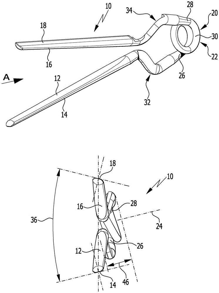
图1和图2示出了例如从现有技术已知的、整体以附图标记10指示的手术夹。该手术夹包括具有第一夹持表面14的第一夹持臂12以及具有第二夹持表面18的第二夹持臂16。此外,夹10包括偏压元件20,该偏压元件20被构造成螺旋弹簧22的形式。FIGS. 1 and 2 show a surgical clip, as known as a whole from the prior art, designated in its entirety by the
偏压元件20用于特别是在偏压下、将第一夹持表面14和第二夹持表面18在基本位置处保持彼此抵靠。The biasing
然而,在图1a和图1b中,夹10未被描绘为处于基本位置,而是被描绘为紧接在夹10生产之后夹持表面14和18不彼此抵靠。由于螺旋弹簧22的作用,夹持臂12和16稍微远离彼此地展开。在夹持臂12和16交叉后,然后螺旋弹簧22在偏压下使夹持表面14和18彼此压靠。However, in Figures 1a and 1b, the
螺旋弹簧22限定螺旋弹簧纵向轴线24。The
螺旋弹簧22具有第一螺旋弹簧端26和第二螺旋弹簧端28。The
在第一螺旋弹簧端26和第二螺旋弹簧端28之间,螺旋弹簧22包括至少一个绕组30,该绕组30在超过360°的周向角上延伸,在图1a和图1b中描绘的实施例中是在约520°的周向角上延伸。Between the first
第一螺旋弹簧端26通过第一连接部32连接到第一夹持臂12。第二螺旋弹簧端28通过第二连接部34连接到第二夹持臂16。The first
当连接部32和34朝向彼此移动,使得第二夹持臂16能够在第一夹持臂12之下接合时,手术夹10处于基本位置。然后,夹持表面14和18彼此充分抵靠,并且通过螺旋弹簧22在偏压下保持彼此压靠。The
图1b示出了从现有技术已知的手术夹的严重问题。当手术夹10由弹簧钢丝坯料形成时,即通过这种方式,使得具有彼此平行地延伸的夹持表面14和18的夹持臂12和16被形成在钢丝坯料的自由端上,螺旋弹簧22的绕组导致夹持表面14和18相对于彼此以角36倾斜。这使得处于基本位置的夹持表面14和18在表面到表面接触时并非彼此抵靠,而是基本仅为线接触。因而,对应的力分量以约15°的角36作用,这使螺旋弹簧22的互相抵接区域彼此压靠。Figure 1b shows a serious problem with surgical clips known from the prior art. When the
在图2至图7中描绘了也以附图标记10指示的改进的手术夹的第一实施例。为了清楚起见,图2至图7中描绘的手术夹的、与从现有技术中已知并且在图1a和图1b中描绘的手术夹10中已经存在的相同部分用相同的附图标记指示。A first embodiment of an improved surgical clip, also indicated at 10, is depicted in FIGS. 2 to 7 . For the sake of clarity, the same parts of the surgical clip depicted in Figures 2 to 7 that are already present in the
如图2至图7中所示,夹10与图1a和图1b的夹的不同特别在于,图2中描绘的处于基本位置的夹持表面14和18以面对面接触彼此抵靠并限定夹持平面38。As shown in Figures 2 to 7, the
与从现有技术已知的夹10的情况不同,螺旋弹簧纵向轴线24平行于夹持平面38延伸。Unlike the case of the
为了实现这一目标,第一螺旋弹簧端26在过渡到第一连接部32的过渡区域中弯成曲柄状。换句话说,第一曲柄40被形成,以便将第一连接部与螺旋弹簧22对准。以类似的方式,第二螺旋弹簧端28和第二连接部34之间的过渡区域弯成曲柄状,使得形成第二曲柄42。To achieve this, the first
在图5和图6中易于看到,由于两个曲柄40和42,所以两个夹持臂12和16关于由螺旋弹簧22限定的螺旋弹簧平面44对称地布置。因此,螺旋弹簧22平行于螺旋弹簧纵向轴线24的最大厚度46小于从现有技术中已知的、如图1a和图1b中描绘的螺旋弹簧10的情况。As can easily be seen in FIGS. 5 and 6 , due to the two
第一连接部32包括两个直线部48和50,这两个直线部48和50相对于彼此以第一弯曲角52成角度。类似地,第二连接部34包括两个直线部54和56,这两个直线部相对于彼此以第二弯曲角58成角度。The first connecting
直线部48直接毗邻第一曲柄40,直线部54毗邻第二曲柄42。直线部50相对于第一夹持臂12以第三弯曲角60成角度。类似地,直线部56相对于第二夹持臂16以第四弯曲角62成角度。The straight portion 48 is directly adjacent to the first crank 40 and the straight portion 54 is adjacent to the
第一连接部32设有从第一夹持臂12开始直到直线部48的扁平部64。以类似方式,第二连接部34设有从第二夹持臂16开始直到直线部54的另一扁平部66。The first connecting
扁平部64和66彼此面对,并限定垂直于螺旋弹簧纵向轴线24以及夹持平面38两者延伸的公共扁平部平面68。扁平部平面68和螺旋弹簧平面44重合。
连接部32和34在扁平部64和66的区域中交叉,由此限定了交叉区域92。The connecting
曲柄40和42用于将夹持表面14和18彼此平行地定向(夹持表面在根据现有技术的、例如在图1a和图1b中描绘的夹10的情况下彼此不平行地延伸),以便通过这种构造实现进一步的上述优点。The
在如图2至图7中描绘的夹10的情况下,螺旋弹簧22被构造成与图1a和图1b中描绘的夹10相同。In the case of the
例如在图8至图13中示意性地描绘了整体以附图标记10指示的改进的手术夹的第二实施例。该手术夹在螺旋弹簧22的设计方面与图2至图7中描绘的夹10不同。A second embodiment of an improved surgical clip, indicated generally at 10, is schematically depicted, for example, in FIGS. 8 to 13 . The surgical clip differs from the
在图8至图13中描绘的夹10的实施例中,螺旋弹簧22包括第一绕组部70和第二绕组部72。第一绕组部70限定第一绕组部平面74,第二绕组部72限定第二绕组部平面76。In the embodiment of the
第一绕组部70毗邻第一曲柄40,第二绕组部72毗邻第二曲柄42。The first winding
此外,第一绕组部70和第二绕组部72通过曲柄部78彼此直接连接。因而,曲柄部78被直接布置或形成在第一绕组部70和第二绕组部72之间。曲柄部78为基本直线构造,并且横切两个绕组部平面74和76地延伸,并且在如图8至图13中描绘的夹10的实施例的情况下,即以约45°的曲柄部角80延伸。Further, the first winding
曲柄部78在第一曲柄部端94处成角度,并连接到第一绕组部70。此外,曲柄部在第二曲柄部端处成角度,并被连接到第二绕组部72。The
绕组部平面74和76平行于彼此并垂直于螺旋弹簧纵向轴线24延伸。The winding
特别如图8中很好地示出的,绕组部70和72每个都在小于360°、特别是小于300°的周向角上延伸。准确地说,所述角度仅为约200°。As best shown in FIG. 8 in particular, the winding
由于具有对应长度的曲柄部78,所以两个绕组部70和72彼此间隔开,并且彼此被绕组部间隙82分开。The two winding
当连接部32和34朝向彼此移动时,螺旋弹簧22被拉到一起。然而,通过曲柄部78确保了绕组部70和72不能与彼此接触,即,独立于夹持臂12和16远离彼此枢转的手术夹10的打开位置。由此能够最小化或甚至完全消除螺旋弹簧22区域中的摩擦力。As the connecting
在图14至图19中示意性地描绘了改进的手术夹10的第三实施例。该手术夹的结构基本对应于如图8至图13中描绘的改进的夹10的第二实施例。A third embodiment of an improved
根据图14至图19的夹10与根据图8至图13的夹相比的主要差异在于,绕组部70和72与其绕组部平面74和76相对于螺旋弹簧平面44以角36倾斜。因此,螺旋弹簧纵向轴线24并非平行于夹持平面38延伸,而是相对于夹持平面以角36倾斜。The main difference between the
如图8至图13中描绘的,夹10因而组合了如图2至图10中描绘的夹10的螺旋弹簧22的特殊特性以及如图14至图19中描绘的夹10的螺旋弹簧22的特殊特性。As depicted in FIGS. 8 to 13 , the
附图中所示的夹10的所有实施例共有的是,第一夹持臂12具有第一自由端84,并且第二夹持臂16具有第二自由端86。Common to all embodiments of the
第一夹持表面14和/或第二夹持表面18可以可选地具有附图中未描绘的夹持表面结构。所述夹持表面结构特别可以是宏观构造或微观构造。The
夹持表面结构特别可以包括夹持凸起和/或夹持凹进。这些夹持凸起和/或夹持凹进特别可以是线性构造和/或点状构造。The gripping surface structure may in particular comprise gripping projections and/or gripping recesses. These clamping projections and/or clamping recesses can in particular be of linear and/or point-like configuration.
图2至图19中描绘的手术夹10的所有实施例都使得与从现有技术已知的手术夹10相比,能够进行更好的操纵。这一方面是由于可选地平行于夹持表面38定向的螺旋弹簧纵向轴线24,或者由于可选地设置的曲柄部78,该曲柄部78将绕组部70和72彼此直接连接,并且以如下方式是所述绕组部彼此保持一定距离,即,使得形成绕组部间隙82。All the embodiments of the
所有改进的夹10都被形成为一个部件,即整体成型。All modified
所有改进的夹10都由弹簧钢丝的坯料制成,该弹簧钢丝具有圆形或基本圆形的横截面。All of the
改进的夹10通过形成坯料、特别是通过压制成型制成。在螺旋弹簧22的区域中的改进的夹10的横截面面积小于夹持臂12和16的区域中的横截面面积。The
此外,夹持臂12和16的夹持臂长度88大于螺旋弹簧22的螺旋弹簧直径90。Additionally, the
附图标记列表List of reference signs
10 夹10 clips
12 第一夹持臂12 First gripping arm
14 第一夹持表面14 First clamping surface
16 第二夹持臂16 Second gripper arm
18 第二夹持表面18 Second clamping surface
20 偏压元件20 Bias element
22 螺旋弹簧22 Coil spring
24 螺旋弹簧纵向轴线24 Longitudinal axis of coil spring
26 第一螺旋弹簧端26 First coil spring end
28 第二螺旋弹簧端28 Second coil spring end
30 绕组30 windings
32 第一连接部32 The first connection part
34 第二连接部34 Second connection part
36 角36 corners
38 夹持平面38 Clamping plane
40 第一曲柄40 first crank
42 第二曲柄42 Second crank
44 螺旋弹簧平面44 Coil Spring Flat
46 厚度46 thickness
48 直线部48 Straight line
50 直线部50 straight line
52 第一弯曲角52 First bend angle
54 直线部54 Straight line
56 直线部56 Straight line
58 第二弯曲角58 Second bend angle
60 第三弯曲角60 Third bend angle
62 第四弯曲角62 Fourth bend angle
64 扁平部64 Flat part
66 扁平部66 Flat part
68 扁平部表面68 Flat surface
70 第一绕组部70 First winding part
72 第二绕组部72 Second winding part
74 第一绕组部平面74 Plane of the first winding part
76 第二绕组部平面76 Second winding plane
78 曲柄部78 Crank part
80 曲柄部角80 crank angle
82 绕组部间隙82 Winding clearance
84 第一自由端84 First free end
86 第二自由端86 Second free end
88 夹持臂长度88 Gripper arm length
90 螺旋弹簧直径90 Coil Spring Diameter
92 交叉区域92 Intersection area
94 第一曲柄部端94 First crank end
96 第二曲柄部端96 Second crank end
Claims (26)
Applications Claiming Priority (3)
| Application Number | Priority Date | Filing Date | Title |
|---|---|---|---|
| DE102018103903.4 | 2018-02-21 | ||
| DE102018103903.4A DE102018103903A1 (en) | 2018-02-21 | 2018-02-21 | Surgical clip |
| PCT/EP2019/054274 WO2019162359A1 (en) | 2018-02-21 | 2019-02-21 | Surgical clip |
Publications (2)
| Publication Number | Publication Date |
|---|---|
| CN112040887A true CN112040887A (en) | 2020-12-04 |
| CN112040887B CN112040887B (en) | 2024-06-18 |
Family
ID=65520280
Family Applications (1)
| Application Number | Title | Priority Date | Filing Date |
|---|---|---|---|
| CN201980014376.9A Active CN112040887B (en) | 2018-02-21 | 2019-02-21 | Surgical clips |
Country Status (7)
| Country | Link |
|---|---|
| US (1) | US11642136B2 (en) |
| EP (1) | EP3755242B1 (en) |
| JP (1) | JP7357627B2 (en) |
| CN (1) | CN112040887B (en) |
| DE (1) | DE102018103903A1 (en) |
| ES (1) | ES2990044T3 (en) |
| WO (1) | WO2019162359A1 (en) |
Families Citing this family (5)
| Publication number | Priority date | Publication date | Assignee | Title |
|---|---|---|---|---|
| CN112165903B (en) * | 2018-05-22 | 2024-11-08 | 波士顿科学国际有限公司 | Tissue bonding device |
| US12220119B2 (en) | 2018-05-22 | 2025-02-11 | Boston Scientific Scimed, Inc. | Tissue engagement device |
| DE102020112781A1 (en) * | 2020-05-12 | 2021-11-18 | Aesculap Ag | Medical clip and method of making a medical implant |
| DE102020122392A1 (en) * | 2020-08-27 | 2022-03-03 | Aesculap Ag | Medical clip and method of making a medical clip |
| DE102021131279A1 (en) | 2021-11-29 | 2023-06-01 | Aesculap Ag | Medical clip, forming tool, forming machine and method of making a medical clip |
Citations (7)
| Publication number | Priority date | Publication date | Assignee | Title |
|---|---|---|---|---|
| US3827438A (en) * | 1972-07-10 | 1974-08-06 | G Kees | Aneurysm clip |
| DE202006010414U1 (en) * | 2006-07-05 | 2006-08-24 | Aesculap Ag & Co. Kg | Surgical clip for clamping a blood vessel during a bypass operation comprises two arms joined together by a spring element and each having an opening running across the longitudinal direction of the arms |
| JP2006305230A (en) * | 2005-05-02 | 2006-11-09 | Mizuho Co Ltd | Aneurysm clip and manufacturing method thereof |
| WO2007006140A1 (en) * | 2005-07-12 | 2007-01-18 | Smart Biotech Inc. | Bioactive aneurysm clip |
| DE102006031092B3 (en) * | 2006-07-05 | 2008-01-24 | Aesculap Ag & Co. Kg | Surgical clip for clamping blood vessels during bypass operations comprises guiding surfaces extending over the whole width of the arms and in the longitudinal direction over the most part of the arm lengths |
| DE102012212629A1 (en) * | 2012-07-18 | 2014-02-20 | Aesculap Ag | Spring-supported clip |
| CN104507401A (en) * | 2012-06-29 | 2015-04-08 | 蛇牌股份公司 | Small Surgical Clamps with Inner Spring |
Family Cites Families (26)
| Publication number | Priority date | Publication date | Assignee | Title |
|---|---|---|---|---|
| JPS5314064B2 (en) | 1973-12-03 | 1978-05-15 | ||
| JPS5314064Y2 (en) * | 1975-05-20 | 1978-04-14 | ||
| US4340061A (en) | 1977-10-25 | 1982-07-20 | Mayfield Education And Research Fund | Aneurysm clip |
| DE3139488C2 (en) * | 1981-10-03 | 1984-08-16 | Aesculap-Werke Ag Vormals Jetter & Scheerer, 7200 Tuttlingen | Aneurysm clip |
| JPS5870209A (en) | 1981-10-23 | 1983-04-26 | Ricoh Co Ltd | optical shutter array |
| JPS5870209U (en) * | 1981-11-06 | 1983-05-12 | 瑞穂医科工業株式会社 | Cerebrovascular surgery clip |
| US4796625A (en) * | 1982-11-15 | 1989-01-10 | Codman & Shurtleff, Inc. | Aneurysm clip |
| US4932955A (en) * | 1984-06-29 | 1990-06-12 | Baxter International Inc. | Clip |
| US4777950A (en) * | 1986-04-11 | 1988-10-18 | Kees Surgical Specialty Co. | Vascular clip |
| US4961743A (en) * | 1989-01-03 | 1990-10-09 | Codman & Shurtleff, Inc. | Torsion spring |
| RU2102017C1 (en) * | 1995-06-06 | 1998-01-20 | Николай Николаевич Волковец | Self-clamping clips |
| DE19827093C2 (en) | 1998-06-18 | 2000-06-08 | Aesculap Ag & Co Kg | Surgical clip |
| US6179850B1 (en) | 1999-01-07 | 2001-01-30 | Tushar Madhu Goradia | Method and apparatus for modulating flow in biological conduits |
| US7077851B2 (en) | 2000-10-17 | 2006-07-18 | Aesculap Ag & Co. Kg | Aneurysm clip |
| WO2002032327A1 (en) | 2000-10-17 | 2002-04-25 | Aesculap Ag & Co. Kg | Aneurysm clip |
| JP4696434B2 (en) * | 2001-09-28 | 2011-06-08 | 株式会社ドクターズ・アイディアル・サプライ | Blood vessel clamping clip |
| DE102004016859B4 (en) * | 2004-04-04 | 2015-08-27 | Peter Lazic Gmbh | Aneurysm clip |
| DE202006002436U1 (en) | 2006-02-16 | 2006-05-04 | Peter Lazic Gmbh | Clip applier |
| US20080004637A1 (en) | 2006-04-29 | 2008-01-03 | Klassen James B | Surgical clip, applicator and applicator methods |
| US20110288571A1 (en) | 2010-05-24 | 2011-11-24 | Aesculap Ag | Surgical clip and surgical method for treating an aneurysm |
| DE102010037468A1 (en) | 2010-09-10 | 2012-03-15 | Aesculap Ag | Surgical clip |
| JP5314064B2 (en) | 2011-02-21 | 2013-10-16 | パナソニック株式会社 | Ottoman and chair type massage machine |
| DE102012103727A1 (en) | 2012-04-27 | 2013-10-31 | Aesculap Ag | One-piece Surgical Clip |
| DE102013200127A1 (en) | 2013-01-08 | 2014-07-10 | Peter Lazic Gmbh | Aneurysm clip |
| DE102013107876A1 (en) | 2013-07-23 | 2015-01-29 | Aesculap Ag | Surgical clip, especially aneurysm clip |
| DE102016107587A1 (en) * | 2016-04-25 | 2017-10-26 | Aesculap Ag | Translated aneurysm clip |
-
2018
- 2018-02-21 DE DE102018103903.4A patent/DE102018103903A1/en not_active Withdrawn
-
2019
- 2019-02-21 CN CN201980014376.9A patent/CN112040887B/en active Active
- 2019-02-21 JP JP2020543990A patent/JP7357627B2/en active Active
- 2019-02-21 ES ES19706969T patent/ES2990044T3/en active Active
- 2019-02-21 WO PCT/EP2019/054274 patent/WO2019162359A1/en not_active Ceased
- 2019-02-21 EP EP19706969.3A patent/EP3755242B1/en active Active
-
2020
- 2020-08-11 US US16/947,638 patent/US11642136B2/en active Active
Patent Citations (7)
| Publication number | Priority date | Publication date | Assignee | Title |
|---|---|---|---|---|
| US3827438A (en) * | 1972-07-10 | 1974-08-06 | G Kees | Aneurysm clip |
| JP2006305230A (en) * | 2005-05-02 | 2006-11-09 | Mizuho Co Ltd | Aneurysm clip and manufacturing method thereof |
| WO2007006140A1 (en) * | 2005-07-12 | 2007-01-18 | Smart Biotech Inc. | Bioactive aneurysm clip |
| DE202006010414U1 (en) * | 2006-07-05 | 2006-08-24 | Aesculap Ag & Co. Kg | Surgical clip for clamping a blood vessel during a bypass operation comprises two arms joined together by a spring element and each having an opening running across the longitudinal direction of the arms |
| DE102006031092B3 (en) * | 2006-07-05 | 2008-01-24 | Aesculap Ag & Co. Kg | Surgical clip for clamping blood vessels during bypass operations comprises guiding surfaces extending over the whole width of the arms and in the longitudinal direction over the most part of the arm lengths |
| CN104507401A (en) * | 2012-06-29 | 2015-04-08 | 蛇牌股份公司 | Small Surgical Clamps with Inner Spring |
| DE102012212629A1 (en) * | 2012-07-18 | 2014-02-20 | Aesculap Ag | Spring-supported clip |
Also Published As
| Publication number | Publication date |
|---|---|
| JP2021514236A (en) | 2021-06-10 |
| DE102018103903A1 (en) | 2019-08-22 |
| EP3755242B1 (en) | 2024-07-03 |
| US11642136B2 (en) | 2023-05-09 |
| CN112040887B (en) | 2024-06-18 |
| WO2019162359A1 (en) | 2019-08-29 |
| US20200367892A1 (en) | 2020-11-26 |
| JP7357627B2 (en) | 2023-10-06 |
| EP3755242A1 (en) | 2020-12-30 |
| ES2990044T3 (en) | 2024-11-28 |
Similar Documents
| Publication | Publication Date | Title |
|---|---|---|
| CN112040887A (en) | Surgical clip | |
| JP6956238B2 (en) | Blocking clip | |
| CN107072671B (en) | Treatment tool for endoscope | |
| KR101061385B1 (en) | Surgical laminated clips | |
| CN104902827B (en) | Endoscopic treatment device | |
| CN104936537B (en) | Fixture unit | |
| CN104869917B (en) | Endoscopic treatment device | |
| JPH029819B2 (en) | ||
| CN103037733B (en) | Tweezers | |
| JP6896855B2 (en) | Clip treatment tool | |
| US20200178966A1 (en) | Fixing device for blood vessel suturing | |
| US11013517B2 (en) | Clip treatment tool | |
| US20200383685A1 (en) | Converted aneurism clip | |
| CN106456186A (en) | Jaw piece with layered construction for surgical instrument | |
| JP6649830B2 (en) | Endoscope treatment tool | |
| US20190380812A1 (en) | Dental instrument with a flexible tip end and method of manufacture | |
| US20120131983A1 (en) | Crimping device | |
| US8147512B1 (en) | Dual closing guide for a surgical instrument | |
| CN106255468A (en) | Surgical clip | |
| JP6822481B2 (en) | Clip removal device | |
| WO2014118930A1 (en) | Crimping tool | |
| JP3135145U (en) | Medical hemostatic clip | |
| CN120154377A (en) | Tissue Closure Clips | |
| CN113573849A (en) | Clamping tool | |
| JP2019039108A (en) | Hair increasing tool and hair increasing method using the same |
Legal Events
| Date | Code | Title | Description |
|---|---|---|---|
| PB01 | Publication | ||
| PB01 | Publication | ||
| SE01 | Entry into force of request for substantive examination | ||
| SE01 | Entry into force of request for substantive examination | ||
| GR01 | Patent grant | ||
| GR01 | Patent grant |