CN112027304B - Conveyor of installation AC distribution box - Google Patents
Conveyor of installation AC distribution box Download PDFInfo
- Publication number
- CN112027304B CN112027304B CN202010731870.1A CN202010731870A CN112027304B CN 112027304 B CN112027304 B CN 112027304B CN 202010731870 A CN202010731870 A CN 202010731870A CN 112027304 B CN112027304 B CN 112027304B
- Authority
- CN
- China
- Prior art keywords
- connecting rod
- distribution box
- fixedly connected
- spring
- pulley
- Prior art date
- Legal status (The legal status is an assumption and is not a legal conclusion. Google has not performed a legal analysis and makes no representation as to the accuracy of the status listed.)
- Active
Links
Images


Classifications
-
- B—PERFORMING OPERATIONS; TRANSPORTING
- B65—CONVEYING; PACKING; STORING; HANDLING THIN OR FILAMENTARY MATERIAL
- B65D—CONTAINERS FOR STORAGE OR TRANSPORT OF ARTICLES OR MATERIALS, e.g. BAGS, BARRELS, BOTTLES, BOXES, CANS, CARTONS, CRATES, DRUMS, JARS, TANKS, HOPPERS, FORWARDING CONTAINERS; ACCESSORIES, CLOSURES, OR FITTINGS THEREFOR; PACKAGING ELEMENTS; PACKAGES
- B65D25/00—Details of other kinds or types of rigid or semi-rigid containers
- B65D25/02—Internal fittings
- B65D25/10—Devices to locate articles in containers
Abstract
The invention relates to the technical field of alternating current distribution equipment, and discloses a conveying device for installing an alternating current distribution box, which comprises a bottom plate, wherein a bearing plate is arranged on the upper side of the bottom plate, a telescopic rod is slidably connected to the left side of a moving cavity, a second spring is arranged on the outer side of the telescopic rod, a stop block is arranged on the right side of the second spring, the left side of the telescopic rod is rotatably connected with a first connecting rod, the front side and the rear side of the middle part of the first connecting rod are rotatably connected with fixed rods, the upper end of the first connecting rod is rotatably connected with a second connecting rod, and a clamping plate is fixedly connected to the right side of the second connecting rod. This installation AC distribution box's conveyor through the effect of block terminal self gravity for remove the first spring of chamber compression, the carriage release lever downstream, the both sides that remove the chamber simultaneously promote the telescopic link and move outward, thereby make first connecting rod to the internal rotation, drive second connecting rod inward movement, thereby make splint press from both sides tight block terminal, thereby reach the effect of transporting stable and not fragile block terminal.
Description
Technical Field
The invention relates to the technical field of alternating current distribution equipment, in particular to a conveying device for installing an alternating current distribution box.
Background
Ac distribution equipment is equipment used to connect power supplies, transformers, converter equipment and other loads, and to monitor and protect the power supply system. The outdoor AC distribution box has the control functions of switching on, switching off and switching between a power supply and various loads and realizing a specified operation mode, wherein the outdoor AC distribution box is a protective shell of AC equipment, and the outdoor AC distribution box is difficult to install in the open air, so the development of installing and transporting the AC distribution box equipment is more and more advanced.
Most installation transports AC distribution box's equipment in the existing market mainly adopts the crane to suspend in midair and transports the operation, and this kind of mode is very unstable when transporting AC distribution box, because inertial action makes AC distribution box sway, damages the block terminal easily, takes place dangerous accident easily, transports the time longer and the installation is very hard. The above situation may cause problems of unstable transportation, easy damage to the distribution box, high risk factor, low transportation efficiency, and high difficulty in installation.
Disclosure of Invention
Technical problem to be solved
Aiming at the defects of the prior art, the invention provides a conveying device for mounting an alternating current distribution box, which has the advantages of stable conveying, difficult damage to the distribution box, low danger coefficient, high conveying efficiency and low mounting difficulty, and solves the problems of unstable conveying, easy damage to the distribution box, high danger coefficient, low conveying efficiency and high mounting difficulty of the conventional distribution box conveying equipment.
(II) technical scheme
In order to realize the purposes of stable transportation, difficult damage of a distribution box, low danger coefficient, high transportation efficiency and low installation difficulty, the invention provides the following technical scheme: a conveying device for installing an alternating current distribution box comprises a bottom plate, wherein a bearing plate is arranged on the upper side of the bottom plate, a guide rail is arranged on the front side of the bearing plate, a rotary disc is arranged on the right side of the bearing plate, a driving shaft is rotatably connected to the middle position of the rotary disc, a sliding block is slidably connected to the inside of the guide rail, a supporting column is arranged on the lower side of the sliding block, a cylindrical block is arranged in the middle of the sliding block, a first pulley is fixedly connected to the middle position of the top of the bearing plate, a second pulley is arranged on the right side of the first pulley, a lifting ladder is arranged on the front portion of the guide rail, a triangular fixing frame is fixedly connected to the upper portion of the lifting ladder, an air chamber is arranged on the left side of the triangular fixing frame, an air pipe is fixedly connected to the left side of the air chamber, an air pump is fixedly connected to the left side of the air pipe, a moving rod is arranged on the upper side of the air chamber, a first spring is arranged on the outer side of the moving rod, a moving chamber is fixedly connected to a moving rod, and a telescopic rod is slidably connected to the left side of the moving chamber, the outside of telescopic link is provided with the second spring, and the right side of second spring is provided with the dog, and the left side of telescopic link is rotated and is connected with first connecting rod, and the middle part front and back side of first connecting rod all rotates and is connected with the dead lever, the trapezoidal fixed block of right side fixedly connected with of dead lever, and the upper end of first connecting rod is rotated and is connected with second connecting rod, the right side fixedly connected with splint of second connecting rod.
Preferably, air chamber, trachea, carriage release lever, first spring, telescopic link, trapezoidal fixed block, second spring, dog, dead lever, first connecting rod, second connecting rod and splint all set up about removing the chamber bilateral symmetry. Through setting up above structure about removing the chamber bilateral symmetry setting for overall structure is more succinct, reaches the maintenance of the later stage equipment of being convenient for and the purpose of maintenance.
Preferably, be provided with the slip track corresponding with the sliding block on the guide rail, thereby through being provided with corresponding slip track for the sliding block slides from top to bottom in the guide rail inside and drives the companion ladder and carry out the lift work.
Preferably, the upside fixedly connected with rope of sliding block, and first pulley, second pulley and carousel pass through the rope and link to each other, carry out the rope through setting up first pulley, second pulley and carousel and link to each other, thereby the carousel tightens up and loosens the up-and-down motion of rope drive sliding block.
Preferably, the elevator is a movable rhomboid quadrangle, and the movable rhomboid quadrangle is set to achieve the purpose of lifting movement.
Preferably, the lower side of the moving rod is provided with a limiting block, and the moving cavity can stably move up and down through the moving rod due to the limiting block.
(III) advantageous effects
Compared with the prior art, the invention provides a conveying device for installing an alternating current distribution box, which has the following beneficial effects:
1. this installation AC distribution box's conveyor through the effect of block terminal self gravity for remove the first spring of chamber compression, thereby the carriage release lever downstream, meanwhile the both sides that remove the chamber promote the telescopic link and outwards move, thereby make first connecting rod to the internal rotation, drive second connecting rod inwardly directed movement, thereby make splint press from both sides tight block terminal, thereby reach the effect of transporting stable and not fragile block terminal.
2. This installation AC distribution box's conveyor, start work through the drive shaft circular telegram, thereby drive the carousel and rotate, thereby tighten up the rope, make the sliding block upward movement, thereby it opens to drive the companion ladder, carry out the rising movement to the triangle mount, when reaching suitable position, drive shaft stall, the rope card dies, the air pump carries out air entrainment work to the air chamber this moment, thereby it promotes the carriage release upward movement to be gaseous, make removal chamber upward movement, the telescopic link resets through the effort of second spring, thereby make splint reset, thereby loosen the block terminal and carry out the installation work, thereby it is low to reach danger coefficient, it is efficient to transport and the effect that the installation degree of difficulty is low.
Drawings
FIG. 1 is a schematic front view of the internal structure of the present invention;
FIG. 2 is a schematic view of the present invention after placement of a power distribution box;
FIG. 3 is a schematic view of the slider structure of the present invention;
FIG. 4 is a perspective view of the splint of the present invention;
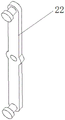
FIG. 5 is a perspective view of a first link according to the present invention;
FIG. 6 is an enlarged view of the invention at A in FIG. 1.
In the figure: 1. a base plate; 2. a carrier plate; 3. a guide rail; 4. an air pump; 5. a drive shaft; 6. a turntable; 7. a slider; 8. a support pillar; 9. a cylindrical block; 10. a second pulley; 11. a first pulley; 12. an elevator; 13. a triangular fixing frame; 14. an air chamber; 15. an air pipe; 16. a travel bar; 17. a first spring; 18. a moving chamber; 19. a telescopic rod; 1901. a stopper; 1902. a second spring; 20. a trapezoidal fixed block; 21. a fixing rod; 22. a first link; 23. a second link; 24. and (4) clamping the plate.
Detailed Description
The technical solutions in the embodiments of the present invention will be clearly and completely described below with reference to the drawings in the embodiments of the present invention, and it is obvious that the described embodiments are only a part of the embodiments of the present invention, and not all of the embodiments. All other embodiments, which can be obtained by a person skilled in the art without making any creative effort based on the embodiments in the present invention, belong to the protection scope of the present invention.
Please refer to fig. 1-6, a conveyor for installing an ac distribution box, which comprises a bottom plate 1, a bearing plate 2 is arranged on the upper side of the bottom plate 1, a guide rail 3 is arranged on the front side of the bearing plate 2, a rotary disc 6 is arranged on the right side of the bearing plate 2, a driving shaft 5 is rotatably connected to the middle position of the rotary disc 6, a sliding block 7 is slidably connected inside the guide rail 3, a rope is fixedly connected to the upper side of the sliding block 7, a first pulley 11, a second pulley 10 and the rotary disc 6 are connected through the rope, the rope connection is performed through the arrangement of the first pulley 11, the second pulley 10 and the rotary disc 6, and the rotary disc 6 tightens up and loosens the rope so as to drive the sliding block 7 to move up and down. Sliding block 7's downside is provided with support column 8, and sliding block 7's middle part is provided with cylinder piece 9, the first pulley 11 of top intermediate position fixedly connected with of carrier plate 2, and first pulley 11's right side is provided with second pulley 10, and the front portion of guide rail 3 is provided with companion ladder 12, and companion ladder 12 sets up to mobilizable rhomboid quadrangle, through setting up to rhomboid quadrangle to reach elevating movement's purpose. The upper portion fixedly connected with triangle mount 13 of companion ladder 12, the inside left side of triangle mount 13 is provided with air chamber 14, the left side fixedly connected with trachea 15 of air chamber 14, the left end fixedly connected with air pump 4 of trachea 15, the upside of air chamber 14 is provided with carriage release lever 16, and the downside of carriage release lever 16 is provided with the stopper, through being provided with the stopper for move chamber 18 and carry out stable up-and-down motion through carriage release lever 16. The outside of carriage release lever 16 is provided with first spring 17, the upside fixedly connected with of carriage release lever 16 removes chamber 18, the left side sliding connection who removes chamber 18 has telescopic link 19, the outside of telescopic link 19 is provided with second spring 1902, the right side of second spring 1902 is provided with dog 1901, the left side of telescopic link 19 is rotated and is connected with first connecting rod 22, the equal rotation in middle part front and back side of first connecting rod 22 is connected with dead lever 21, the trapezoidal fixed block 20 of right side fixedly connected with of dead lever 21, the upper end of first connecting rod 22 is rotated and is connected with second connecting rod 23, the right side fixedly connected with splint 24 of second connecting rod 23. The guide rail 3 is provided with a sliding track corresponding to the sliding block 7, and the sliding block 7 slides up and down in the guide rail through the corresponding sliding track so as to drive the elevator 12 to lift. The air chamber 14, the air pipe 15, the moving rod 16, the first spring 17, the telescopic rod 19, the trapezoidal fixing block 20, the second spring 1902, the stopper 1901, the fixing rod 21, the first connecting rod 22, the second connecting rod 23 and the clamping plate 24 are arranged in bilateral symmetry with respect to the moving cavity 18. Through setting up above structure and about removing 18 bilateral symmetry settings in chamber for overall structure is more succinct, reaches the purpose of the maintenance and the maintenance of the equipment of the later stage of being convenient for.
The working principle is as follows: when the device works, fig. 1 is an initial state, an alternating current distribution box is placed in a moving cavity 18, the device is in a state shown in fig. 2, the moving cavity 18 compresses a first spring 17 under the action of the gravity of the distribution box, so that a moving rod 16 moves downwards, meanwhile, two sides of the moving cavity 18 push telescopic rods 19 to move outwards, so that a first connecting rod 22 rotates inwards to drive a second connecting rod 23 to move inwards, a clamping plate 24 clamps the distribution box to stably convey the distribution box, a driving shaft 5 is electrified to start working at the moment to drive a rotary disc 6 to rotate, so that a rope is tightened, a sliding block 7 moves upwards to drive an elevator 12 to open, a triangular fixing frame 13 is lifted, when a proper position is reached, the driving shaft 5 stops rotating, the rope is clamped, at the moment, an air pump 4 carries out air charging work on an air chamber 14, and gas pushes the moving rod 16 to move upwards, so that move chamber 18 upward movement, telescopic link 19 resets through the effort of second spring 1902 to make splint 24 reset, loosen the block terminal thereby install work, so relapse the workflow that this device promptly.
To sum up, this installation AC distribution box's conveyor through the effect of block terminal self gravity for remove the first spring 17 of 18 compressions in chamber, thereby the carriage release lever 16 downstream, and meanwhile the both sides that remove chamber 18 promote the outside motion of telescopic link 19, thereby make first connecting rod 22 inwards rotate, drive second connecting rod 23 inwards motion, thereby make splint 24 press from both sides tight block terminal, thereby reach the effect of transporting stable and not fragile block terminal. Work is started through 5 circular telegrams of drive shaft, thereby drive carousel 6 and rotate, thereby tighten up the rope, make sliding block 7 upward movement, thereby drive companion ladder 12 and open, carry out the rising movement to triangle mount 13, when reaching suitable position, drive shaft 5 stall, the rope card is dead, air pump 4 carries out air entrainment work to air chamber 14 this moment, thereby it promotes the 16 upward movements of carriage release lever to be gaseous, make and remove 18 upward movements in chamber, telescopic link 19 resets through the effort of second spring 1902, thereby make splint 24 reset, thereby loosen the block terminal and carry out installation work, thereby it is low to reach danger coefficient, transport efficiency height and the effect that the installation degree of difficulty is low.
Although embodiments of the present invention have been shown and described, it will be appreciated by those skilled in the art that changes, modifications, substitutions and alterations can be made in these embodiments without departing from the principles and spirit of the invention, the scope of which is defined in the appended claims and their equivalents.
Claims (6)
1. The utility model provides an installation AC distribution box's conveyer, includes bottom plate (1), its characterized in that: the upper side of the bottom plate (1) is provided with a bearing plate (2), the front side of the bearing plate (2) is provided with a guide rail (3), the right side of the bearing plate (2) is provided with a turntable (6), the middle position of the turntable (6) is rotatably connected with a driving shaft (5), the inner part of the guide rail (3) is slidably connected with a sliding block (7), the lower side of the sliding block (7) is provided with a support column (8), the middle part of the sliding block (7) is provided with a cylindrical block (9), the middle position of the top of the bearing plate (2) is fixedly connected with a first pulley (11), the right side of the first pulley (11) is provided with a second pulley (10), the front part of the guide rail (3) is provided with a lifting ladder (12), the upper part of the lifting ladder (12) is fixedly connected with a triangular fixing frame (13), the inner left side of the triangular fixing frame (13) is provided with an air chamber (14), and the left side of the air chamber (14) is fixedly connected with an air pipe (15), the left end fixedly connected with air pump (4) of trachea (15), the upside of air chamber (14) is provided with carriage release lever (16), the outside of carriage release lever (16) is provided with first spring (17), the upside fixedly connected with of carriage release lever (16) removes chamber (18), the left side sliding connection who removes chamber (18) has telescopic link (19), the outside of telescopic link (19) is provided with second spring (1902), the right side of second spring (1902) is provided with dog (1901), the left side of telescopic link (19) is rotated and is connected with first connecting rod (22), the middle part front and back side of first connecting rod (22) all rotates and is connected with dead lever (21), the trapezoidal fixed block (20) of right side fixedly connected with of dead lever (21), the upper end rotation of first connecting rod (22) is connected with second connecting rod (23), the right side fixedly connected with splint (24) of second connecting rod (23).
2. The apparatus for mounting an ac distribution box according to claim 1, wherein: air chamber (14), trachea (15), carriage release lever (16), first spring (17), telescopic link (19), trapezoidal fixed block (20), second spring (1902), dog (1901), dead lever (21), first connecting rod (22), second connecting rod (23) and splint (24) all set up about removing chamber (18) bilateral symmetry.
3. A conveyor assembly for mounting an ac distribution box according to claim 1 further comprising: and a sliding track corresponding to the sliding block (7) is arranged on the guide rail (3).
4. The apparatus for mounting an ac distribution box according to claim 1, wherein: the upside fixedly connected with rope of sliding block (7), and first pulley (11), second pulley (10) and carousel (6) link to each other through the rope.
5. A conveyor assembly for mounting an ac distribution box according to claim 1 further comprising: the elevator (12) is arranged to be a movable rhombus quadrangle.
6. A conveyor assembly for mounting an ac distribution box according to claim 1 further comprising: and a limiting block is arranged on the lower side of the moving rod (16).
Priority Applications (1)
| Application Number | Priority Date | Filing Date | Title |
|---|---|---|---|
| CN202010731870.1A CN112027304B (en) | 2020-07-27 | 2020-07-27 | Conveyor of installation AC distribution box |
Applications Claiming Priority (1)
| Application Number | Priority Date | Filing Date | Title |
|---|---|---|---|
| CN202010731870.1A CN112027304B (en) | 2020-07-27 | 2020-07-27 | Conveyor of installation AC distribution box |
Publications (2)
| Publication Number | Publication Date |
|---|---|
| CN112027304A CN112027304A (en) | 2020-12-04 |
| CN112027304B true CN112027304B (en) | 2022-08-26 |
Family
ID=73583246
Family Applications (1)
| Application Number | Title | Priority Date | Filing Date |
|---|---|---|---|
| CN202010731870.1A Active CN112027304B (en) | 2020-07-27 | 2020-07-27 | Conveyor of installation AC distribution box |
Country Status (1)
| Country | Link |
|---|---|
| CN (1) | CN112027304B (en) |
Families Citing this family (2)
| Publication number | Priority date | Publication date | Assignee | Title |
|---|---|---|---|---|
| CN112850547B (en) * | 2021-01-06 | 2022-05-13 | 崇义县惠客园农业发展有限公司 | Oranges and tangerines are picked with supplementary device of getting on bus |
| CN113263462A (en) * | 2021-07-05 | 2021-08-17 | 哈尔滨东安华孚机械制造有限公司 | Workpiece fixing device and method for cylinder cover machining |
Family Cites Families (5)
| Publication number | Priority date | Publication date | Assignee | Title |
|---|---|---|---|---|
| CN106704779B (en) * | 2017-03-29 | 2018-12-11 | 宁波渠成进出口有限公司 | A kind of lift display screen hanger |
| CN207001146U (en) * | 2017-07-14 | 2018-02-13 | 泰州亚泰金属有限公司 | A kind of strong column conveying arrangement of stability |
| CN108502320B (en) * | 2018-03-26 | 2019-11-29 | 阜阳知麓信息科技有限公司 | A kind of fixed device of power equipment being readily transported |
| CN208377345U (en) * | 2018-07-09 | 2019-01-15 | 洛阳花开帝都牡丹瓷文化发展有限公司 | A kind of shock-absorption device case for peony porcelain transport |
| CN209290986U (en) * | 2018-11-28 | 2019-08-23 | 金华市金东彩印厂(普通合伙) | A kind of cartons for white spirit convenient for pick-and-place |
-
2020
- 2020-07-27 CN CN202010731870.1A patent/CN112027304B/en active Active
Also Published As
| Publication number | Publication date |
|---|---|
| CN112027304A (en) | 2020-12-04 |
Similar Documents
| Publication | Publication Date | Title |
|---|---|---|
| CN112027304B (en) | Conveyor of installation AC distribution box | |
| CN106809632A (en) | The handling equipment of horizontal oxidation line | |
| CN206537898U (en) | The handling equipment of horizontal oxidation line | |
| CN212841163U (en) | High-pole lamp lifting device | |
| CN115264305A (en) | Power equipment maintenance strutting arrangement | |
| CN210064180U (en) | Hang chain and go up lower part mechanism | |
| CN203411093U (en) | Automatic loading and unloading device for refractory bricks | |
| CN117508304B (en) | Building construction prevents tong template transfer device | |
| CN208687299U (en) | A kind of weaving taping machine support device convenient for adjusting height | |
| CN219707064U (en) | Conveyer for distribution switch control equipment | |
| CN112938342A (en) | Elevator auxiliary device for elevator to discharge from high place conveniently | |
| CN111099516A (en) | Remote control lifting trolley | |
| CN218786497U (en) | Roof steel structure vertical transportation device | |
| CN220578156U (en) | Lifting machine for glass bottle production | |
| CN220220749U (en) | Landscape bonsai moving device | |
| CN212198334U (en) | Lifting trolley | |
| CN210029947U (en) | Supporting device for maintenance of hoisting equipment | |
| CN213537051U (en) | Gantry crane with electric hoist | |
| CN216239641U (en) | Movable operation platform for building construction | |
| CN212712554U (en) | Material conveying and lifting equipment for bridge construction of bridge engineering | |
| CN214030783U (en) | Engine flywheel handling device | |
| CN214215891U (en) | Goods lifting and placing device for logistics management | |
| CN216807880U (en) | Vertical installation equipment for frequency converter of drive cabinet | |
| CN218841005U (en) | Pole piece carrying equipment | |
| CN218810020U (en) | Auxiliary device is dismantled to bearing roller |
Legal Events
| Date | Code | Title | Description |
|---|---|---|---|
| PB01 | Publication | ||
| PB01 | Publication | ||
| SE01 | Entry into force of request for substantive examination | ||
| SE01 | Entry into force of request for substantive examination | ||
| TA01 | Transfer of patent application right | ||
| TA01 | Transfer of patent application right |
Effective date of registration: 20220809 Address after: 441002 No. 15, Changhong Road, Fancheng District, Xiangyang City, Hubei Province Applicant after: XIANGYANG POWER SUPPLY COMPANY OF STATE GRID HUBEI ELECTRIC POWER Co.,Ltd. Address before: East of Renmin Avenue, Shicheng Town, Lianjiang City, Zhanjiang City, Guangdong Province, 524499 Applicant before: Huang Xiaohui |
|
| GR01 | Patent grant | ||
| GR01 | Patent grant |