CN112003182A - Intelligent grounding system applied to high-voltage cable - Google Patents
Intelligent grounding system applied to high-voltage cable Download PDFInfo
- Publication number
- CN112003182A CN112003182A CN202010876859.4A CN202010876859A CN112003182A CN 112003182 A CN112003182 A CN 112003182A CN 202010876859 A CN202010876859 A CN 202010876859A CN 112003182 A CN112003182 A CN 112003182A
- Authority
- CN
- China
- Prior art keywords
- grounding
- connecting rod
- ground
- plate
- switch
- Prior art date
- Legal status (The legal status is an assumption and is not a legal conclusion. Google has not performed a legal analysis and makes no representation as to the accuracy of the status listed.)
- Granted
Links
Images


Classifications
-
- H—ELECTRICITY
- H02—GENERATION; CONVERSION OR DISTRIBUTION OF ELECTRIC POWER
- H02G—INSTALLATION OF ELECTRIC CABLES OR LINES, OR OF COMBINED OPTICAL AND ELECTRIC CABLES OR LINES
- H02G1/00—Methods or apparatus specially adapted for installing, maintaining, repairing or dismantling electric cables or lines
-
- H—ELECTRICITY
- H02—GENERATION; CONVERSION OR DISTRIBUTION OF ELECTRIC POWER
- H02J—CIRCUIT ARRANGEMENTS OR SYSTEMS FOR SUPPLYING OR DISTRIBUTING ELECTRIC POWER; SYSTEMS FOR STORING ELECTRIC ENERGY
- H02J13/00—Circuit arrangements for providing remote indication of network conditions, e.g. an instantaneous record of the open or closed condition of each circuitbreaker in the network; Circuit arrangements for providing remote control of switching means in a power distribution network, e.g. switching in and out of current consumers by using a pulse code signal carried by the network
- H02J13/00032—Systems characterised by the controlled or operated power network elements or equipment, the power network elements or equipment not otherwise provided for
- H02J13/00036—Systems characterised by the controlled or operated power network elements or equipment, the power network elements or equipment not otherwise provided for the elements or equipment being or involving switches, relays or circuit breakers
Abstract
The invention relates to an intelligent grounding system applied to a high-voltage cable, which comprises a support, wherein a plurality of pillar magnetic bottles are arranged at the upper end of the support, electric connection terminals are arranged on the pillar magnetic bottles, a grounding plate is arranged on the support and below the pillar magnetic bottles, a first grounding block and a second grounding block are arranged on the grounding plate, a first grounding block is connected between the first grounding block and the pillar magnetic bottles, a second grounding block is connected between the second grounding block and the pillar magnetic bottles, a first grounding switch for realizing the electric connection of the first grounding block and the first grounding block is arranged on the grounding plate, a second grounding switch for realizing the electric connection of the second grounding block and the second grounding block is arranged on the grounding plate, and an electric mechanism for driving the first grounding switch and the second grounding switch or turning off the first grounding switch and the second grounding switch is arranged on the support. The intelligent grounding operation of the high-voltage cable is realized, and the whole operation process is mechanical operation, so that the stability of the operation of grounding connection is effectively improved.
Description
Technical Field
The invention relates to the technical field of power equipment, in particular to an intelligent grounding system applied to a high-voltage cable.
Background
The high-voltage cable has replaced the overhead line and becomes the first choice of city core area electric wire netting, and the reasonable ground connection of high-voltage cable metal sheath is its safe guarantee of operation. The high-voltage cable is attractive in appearance, high in reliability and land-saving, meets the development requirements of urban power grids, and basically replaces an overhead line in the main area of each big city in China to become the first choice of the power grid in the core area of the city. The high-voltage cable sheath grounding wire and grounding current on-line detection system is an important component for building an intelligent power grid. Most of the existing grounding systems for high-voltage cables are controlled by electrical components or electric control parts, which are poor in stability and low in safety, so that an intelligent grounding system applied to the high-voltage cables needs to be developed urgently to solve the problems in the prior art.
Disclosure of Invention
The present invention is directed to an intelligent grounding system for high voltage cables, which solves the above problems.
In order to achieve the purpose, the invention provides the following technical scheme:
the utility model provides an intelligence ground system for high tension cable, includes the support, the support upper end is equipped with a plurality of pillar magnetism bottle, all be equipped with the electrical connection terminal on the pillar magnetism bottle, the below that just is located pillar magnetism bottle on the support is equipped with the ground plate, be equipped with first grounding piece and second grounding piece on the ground plate, be connected with first electricity piece that connects between first grounding piece and the pillar magnetism bottle, be connected with the second electricity piece between second grounding piece and the pillar magnetism bottle, be equipped with the first earthing switch who realizes first electricity piece and first grounding piece electricity and be connected on the ground plate, be equipped with the second earthing switch who realizes that the second electricity piece and second grounding piece electricity are connected on the ground plate, be equipped with the electric mechanism who drives first earthing switch and second earthing switch or close on the support.
Preferably, a main knife linkage connecting rod is arranged on the first grounding switch, one end, far away from the first grounding switch, of the main knife linkage connecting rod is connected with a main knife vertical connecting rod, and the main knife vertical connecting rod is in transmission connection with the electric mechanism.
Preferably, the second grounding switch is connected with a grounding knife linkage connecting rod, one end of the grounding knife linkage connecting rod, which is far away from the second grounding switch, is connected with a grounding knife vertical connecting rod, and a single-phase linkage connecting rod, a main knife three-phase horizontal connecting rod and a grounding knife three-phase horizontal connecting rod are connected between the first grounding switch and the second grounding switch.
Preferably, universal joints are connected between the main knife linkage connecting rod and the main knife vertical connecting rod and between the ground knife linkage connecting rod and the ground knife vertical connecting rod.
Preferably, one side of the support is provided with a mounting rack, and the mounting rack is provided with a guide sleeve for the main knife vertical connecting rod and the ground knife vertical connecting rod to penetrate through.
Preferably, the guide sleeve is internally provided with a mounting cavity, the mounting cavity is internally provided with a mounting plate, the mounting plate is provided with a rotating shaft, and the periphery of the rotating shaft is provided with a guide wheel.
Preferably, the periphery of leading wheel cup joints the rubber cushion collar.
Preferably, the bottom is equipped with first piston in the installation cavity, one side that first piston is close to the mounting panel is equipped with the piston axle, one side that the piston axle is close to the mounting panel is equipped with the second piston, the second piston is fixed on the mounting panel, be equipped with the spring between first piston and the second piston, the spring cup joints the periphery at the piston axle.
Preferably, first grounding piece all includes the movable sleeve and runs through the conducting rod of movable sleeve with the second grounding piece, the conducting rod is connected with ground plate and pillar magnetism bottle electricity respectively, be equipped with movable chamber in the movable tube, the conducting rod forms the slot at the movable intracavity, be equipped with the loose axle of pegging graft in movable intracavity in the loose axle, one side that the loose axle is close to the conducting rod is equipped with the electrically conductive picture peg of pegging graft in the slot, electrically conductive picture peg and conducting rod contact setting when pegging graft in the slot, the one end that the conducting rod was kept away from to the loose axle is equipped with the atress board, be equipped with the buffer board on the atress board.
Preferably, the inner wall of the movable pipe is provided with a guide groove, and the periphery of the movable shaft is provided with a guide rib which moves along the guide groove.
Compared with the prior art, the invention has the beneficial effects that: during the use, by the first earthing switch of electric mechanism drive and second earthing switch open or close, by the first earthing switch of first earthing switch and second earthing switch open or close realize first earthing switch that first electricity piece and first earthing block electricity are connected, and the second earthing switch that second electricity piece and second earthing block electricity are connected, so realized the electric drive control of ground connection, and motor mechanism can be controlled through the computer by long-range control center, the intelligence ground operation of high tension cable has been realized, whole process of controlling is mechanical control, thereby the stability of ground connection control has effectively been improved.
Other features and advantages of the present invention will be disclosed in more detail in the following detailed description of the invention and the accompanying drawings.
Drawings
Fig. 1 is a top view of an intelligent grounding system for high voltage cables according to the present invention;
fig. 2 is a front view of the intelligent grounding system applied to the high voltage cable according to the present invention;
fig. 3 is a side view of the intelligent grounding system applied to the high voltage cable according to the present invention;
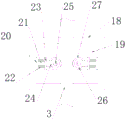
fig. 4 is a sectional view of a guide sleeve applied to an intelligent grounding system for a high voltage cable according to the present invention;
fig. 5 is a cross-sectional view of a first power connection block or a second power connection block in the intelligent grounding system for high-voltage cables according to the present invention.
In the figure: 1. a pillar magnetic bottle; 2. a universal joint; 3. a main knife vertical connecting rod; 4. a ground cutter vertical connecting rod; 5. an electric mechanism; 6. a single-phase linkage connecting rod; 7. a main knife linkage connecting rod; 8. a main knife three-phase horizontal connecting rod; 9. the ground cutter is linked with the connecting rod; 10. a three-phase horizontal connecting rod of the ground cutter; 11. a support; 12. an electric terminal is connected; 13. a first ground switch; 14. a second ground switch; 15. a first ground block; 16. a second ground block; 17. a ground plate; 18. a guide sleeve; 19. a mounting cavity; 20. a first piston; 21. a piston shaft; 22. a spring; 23. a second piston; 24. mounting a plate; 25. a rotating shaft; 26. a guide wheel; 27. a rubber cushion sleeve; 28. a first power connection block; 29. a second power connection block; 30. a mounting frame; 31. a movable shaft; 32. a stress plate; 33. a buffer plate; 34. a movable tube; 35. a guide groove; 36. a conductive plug board; 37. a movable cavity; 38. a guide rib; 39. a conductive rod; 40. and (4) a slot.
Detailed Description
The technical solutions in the embodiments of the present invention will be clearly and completely described below with reference to the drawings in the embodiments of the present invention, and it is obvious that the described embodiments are only a part of the embodiments of the present invention, and not all of the embodiments. All other embodiments, which can be derived by a person skilled in the art from the embodiments given herein without making any creative effort, shall fall within the protection scope of the present invention.
Referring to fig. 1 to 5, in an embodiment of the present invention, an intelligent grounding system applied to a high voltage cable includes a bracket 11, the upper end of the bracket 11 is provided with a plurality of pillar magnetic bottles 1, the pillar magnetic bottles 1 are all provided with electric terminals 12, a grounding plate 17 is arranged on the bracket 11 and below the pillar magnetic bottle 1, a first grounding block 15 and a second grounding block 16 are arranged on the grounding plate 17, a first electric connection block 28 is connected between the first grounding block 15 and the support magnetic bottle 1, a second electric connection block 29 is connected between the second grounding block 16 and the support magnetic bottle 1, the grounding plate 17 is provided with a first grounding switch 13 for realizing the electric connection between the first grounding block 28 and the first grounding block 15, the grounding plate 17 is provided with a second grounding switch 14 for realizing the electrical connection between the second grounding block 29 and the second grounding block 16, and an electric mechanism 5 for driving the first grounding switch 13 and the second grounding switch 14 to be turned off is arranged on the bracket 11. When the grounding control device is used, the electric mechanism 5 drives the first grounding switch 13 and the second grounding switch 14 to be turned on or turned off, the first grounding switch 13 with the first grounding block 28 electrically connected with the first grounding block 15 is turned on or turned off by the first grounding switch 13 and the second grounding switch 14 with the second grounding block 29 electrically connected with the second grounding block 16, so that the electric driving control of grounding is realized, the motor mechanism can be controlled by a remote control center through a computer, the intelligent grounding operation of a high-voltage cable is realized, the whole control process is mechanical control, and the stability of grounding connection control is effectively improved.
In this embodiment, the first grounding switch 13 is provided with a main knife linkage connecting rod 7, one end of the main knife linkage connecting rod 7, which is far away from the first grounding switch 13, is connected with a main knife vertical connecting rod, and the main knife vertical connecting rod is in transmission connection with the electric mechanism 5. The main knife linkage connecting rod 7 is arranged on the first grounding switch 13, one end, far away from the first grounding switch 13, of the main knife linkage connecting rod 7 is connected with the main knife vertical connecting rod 3, the main knife vertical connecting rod 3 is in transmission connection with the electric mechanism 5, the electric mechanism 5 drives the main knife vertical connecting rod 3 and the ground knife vertical connecting rod 4 to move, the main knife vertical connecting rod 3 and the ground knife vertical connecting rod 4 drive the ground knife linkage connecting rod 9 and the main knife linkage connecting rod 7 to move, opening or closing of the first grounding switch 13 and the second grounding switch 14 is achieved, and control over grounding connection or disconnection is facilitated.
In this embodiment, the second grounding switch 14 is connected to a grounding-blade linkage link 9, one end of the grounding-blade linkage link 9, which is far away from the second grounding switch 14, is connected to a grounding-blade vertical link 4, and a single-phase linkage link 6, a main-blade three-phase horizontal link 8 and a grounding-blade three-phase horizontal link 10 are connected between the first grounding switch 13 and the second grounding switch 14. Through be connected with ground sword linkage connecting rod 9 on second earthing switch 14, the one end that second earthing switch 14 was kept away from to ground sword linkage connecting rod 9 is connected with the perpendicular connecting rod 4 of ground sword, is connected with single-phase interlock connecting rod 6 and main sword three-phase horizontal connecting rod 8 between first earthing switch 13 and the second earthing switch 14, so made things convenient for first earthing switch 13 and second earthing switch 14 to open or close.
In the embodiment, universal joints 2 are connected between the main-cutter linkage connecting rod 7 and the main-cutter vertical connecting rod 3 and between the ground-cutter linkage connecting rod 9 and the ground-cutter vertical connecting rod 4. Through setting up universal joint 2, can improve the stability of rotating between main sword linkage connecting rod 7 and the perpendicular connecting rod 3 of main sword to and the stability of rotating between ground sword linkage connecting rod 9 and the perpendicular connecting rod 4 of ground sword.
In this embodiment, a mounting bracket 30 is provided at one side of the support 11, and a guide sleeve 18 for penetrating the main blade vertical connecting rod 3 and the ground blade vertical connecting rod 4 is provided on the mounting bracket 30. The main knife vertical connecting rod 3 and the ground knife vertical connecting rod 4 are limited and guided through the guide sleeve 18, and the moving stability of the main knife vertical connecting rod 3 and the ground knife vertical connecting rod 4 is improved.
In this embodiment, a mounting cavity 19 is formed in the guide sleeve 18, a mounting plate 24 is formed in the mounting cavity 19, a rotating shaft 25 is arranged on the mounting plate 24, and a guide wheel 26 is arranged on the periphery of the rotating shaft 25. The installation cavity 19 is arranged in the guide sleeve 18, the installation plate 24 is arranged in the installation cavity 19, the rotating shaft 25 is arranged on the installation plate 24, the guide wheel 26 is sleeved outside the rotating shaft 25, and the guide wheel 26 is arranged, so that the movable limiting guide of the ground cutter vertical connecting rod 4 and the main cutter vertical connecting rod 3 is realized, and the movable stability of the ground cutter vertical connecting rod 4 and the main cutter vertical connecting rod 3 is improved.
In this embodiment, a rubber cushion sleeve 27 is sleeved on the outer periphery of the guide wheel 26. Through cup jointing rubber buffer sleeve 27 in the periphery of leading wheel 26, rubber buffer sleeve 27's setting has realized the shock attenuation buffering, has improved the stability of the perpendicular connecting rod of ground sword 4 and the perpendicular connecting rod of main sword 3 activity.
In this embodiment, the bottom is equipped with first piston 20 in installation cavity 19, one side that first piston 20 is close to mounting panel 24 is equipped with piston shaft 21, one side that piston shaft 21 is close to mounting panel 24 is equipped with second piston 23, second piston 23 is fixed on mounting panel 24, be equipped with spring 22 between first piston 20 and the second piston 23, spring 22 cup joints the periphery at piston shaft 21. Through establishing first piston 20, piston shaft 21 and second piston 23 at the bottom in installation cavity 19, piston shaft 21 is flexible in first piston 20 and second piston 23, has realized that leading wheel 26 is flexible in the horizontal direction, and leading wheel 26 flexible has made things convenient for the direction to the activity of main sword vertical connecting rod 3 and ground sword vertical connecting rod 4, has improved the stability of the activity of main sword vertical connecting rod 3 and ground sword vertical connecting rod 4, and then has improved the stability of ground connection and disconnection operation.
In this embodiment, first ground connection piece 15 all includes the movable sleeve and runs through the conducting rod 39 of movable sleeve with second ground connection piece 16, conducting rod 39 is connected with ground plate 17 and pillar magnetism bottle 1 electricity respectively, be equipped with movable chamber 37 in the movable tube 34, conducting rod 39 forms slot 40 in movable chamber 37, be equipped with the loose axle 31 of pegging graft in movable chamber 37 in the movable tube 34, one side that the loose axle 31 is close to conducting rod 39 is equipped with the electrically conductive picture peg 36 that can peg graft in slot 40, electrically conductive picture peg 36 when pegging graft in slot 40, electrically conductive picture peg 36 and conducting rod 39 contact setting, the one end that conducting rod 39 was kept away from to loose axle 31 is equipped with atress board 32, be equipped with buffer board 33 on the atress board 32. The first grounding switch 13 and the second grounding switch 14 are turned on or off to apply force to the buffer plate 33, the buffer plate 33 drives the stress plate 32 to enable the movable shaft 31 to move along the movable cavity 37, the conductive inserting plate 36 is inserted into the slot 40 between the conductive rods 39, the conductive inserting plate 36 is connected with the conductive rods 39 to achieve grounding, and the stability of grounding connection or disconnection is improved.
In this embodiment, the inner wall of the movable tube 34 is provided with a guide groove 35, and the outer periphery of the movable shaft 31 is provided with a guide rib 38 which moves along the guide groove 35. Through establishing guide way 35 at the inner wall of activity pipe 34, the periphery of loose axle 31 is established and is followed the direction muscle 38 of guide way 35 activity, so can effectively improve the stability of loose axle 31 activity, improved the stability of ground connection or disconnection.
As can be appreciated, it is possible to,
it will be evident to those skilled in the art that the invention is not limited to the details of the foregoing illustrative embodiments, and that the present invention may be embodied in other specific forms without departing from the spirit or essential attributes thereof. The present embodiments are therefore to be considered in all respects as illustrative and not restrictive, the scope of the invention being indicated by the appended claims rather than by the foregoing description, and all changes which come within the meaning and range of equivalency of the claims are therefore intended to be embraced therein. Any reference sign in a claim should not be construed as limiting the claim concerned.
Furthermore, it should be understood that although the present description refers to embodiments, not every embodiment may contain only a single embodiment, and such description is for clarity only, and those skilled in the art should integrate the description, and the embodiments may be combined as appropriate to form other embodiments understood by those skilled in the art.
Claims (10)
1. The utility model provides an intelligence ground system for high tension cable, a serial communication port, which comprises a bracket, the support upper end is equipped with a plurality of pillar magnetism bottle, all be equipped with the electrical connection terminal on the pillar magnetism bottle, the below that just is located the pillar magnetism bottle on the support is equipped with the ground plate, be equipped with first grounding piece and second grounding piece on the ground plate, be connected with first grounding piece between first grounding piece and the pillar magnetism bottle, be connected with the second grounding piece between second grounding piece and the pillar magnetism bottle, be equipped with the first ground switch that realizes first grounding piece and first grounding piece electricity and be connected on the ground plate, be equipped with the second ground switch that realizes second grounding piece and second grounding piece electricity and be connected on the ground plate, be equipped with the electronic mechanism of the first ground switch of drive and second ground switch or closing on the support.
2. The intelligent grounding system applied to the high-voltage cable according to claim 1, wherein the first grounding switch is provided with a main knife linkage connecting rod, one end of the main knife linkage connecting rod, which is far away from the first grounding switch, is connected with a main knife vertical connecting rod, and the main knife vertical connecting rod is in transmission connection with an electric mechanism.
3. The intelligent grounding system applied to the high-voltage cable according to claim 2, wherein a grounding knife linkage connecting rod is connected to the second grounding switch, a grounding knife vertical connecting rod is connected to one end of the grounding knife linkage connecting rod, which is far away from the second grounding switch, and a single-phase linkage connecting rod, a main knife three-phase horizontal connecting rod and a grounding knife three-phase horizontal connecting rod are connected between the first grounding switch and the second grounding switch.
4. The intelligent grounding system applied to the high-voltage cable as claimed in claim 2, wherein universal joints are connected between the main knife linkage connecting rod and the main knife vertical connecting rod and between the ground knife linkage connecting rod and the ground knife vertical connecting rod.
5. The intelligent grounding system applied to the high-voltage cable as claimed in claim 1, wherein a mounting frame is disposed on one side of the support, and a guide sleeve for the main knife vertical connecting rod and the ground knife vertical connecting rod to penetrate is disposed on the mounting frame.
6. The intelligent grounding system applied to high-voltage cables as claimed in claim 5, wherein a mounting cavity is arranged in the guide sleeve, a mounting plate is arranged in the mounting cavity, a rotating shaft is arranged on the mounting plate, and a guide wheel is arranged on the periphery of the rotating shaft.
7. The intelligent grounding system applied to the high-voltage cable according to claim 6, wherein a rubber buffer sleeve is sleeved on the periphery of the guide wheel.
8. The intelligent grounding system applied to the high-voltage cable is characterized in that a first piston is arranged at the bottom in the installation cavity, a piston shaft is arranged on one side, close to the installation plate, of the first piston, a second piston is arranged on one side, close to the installation plate, of the piston shaft, the second piston is fixed on the installation plate, a spring is arranged between the first piston and the second piston, and the spring is sleeved on the periphery of the piston shaft.
9. The intelligent grounding system applied to the high-voltage cable is characterized in that the first grounding block and the second grounding block respectively comprise a movable sleeve and a conductive rod penetrating through the movable sleeve, the conductive rod is respectively electrically connected with a grounding plate and a supporting column magnetic bottle, a movable cavity is arranged in the movable tube, the conductive rod forms a slot in the movable cavity, a movable shaft inserted in the movable cavity is arranged in the movable tube, a conductive inserting plate capable of being inserted in the slot is arranged on one side, close to the conductive rod, of the movable shaft, the conductive inserting plate is contacted with the conductive rod when the conductive inserting plate is inserted in the slot, a stress plate is arranged at one end, far away from the conductive rod, of the movable shaft, and a buffer plate is arranged on the stress plate.
10. The intelligent grounding system applied to high-voltage cables as claimed in claim 9, wherein the inner wall of the movable tube is provided with a guide groove, and the outer periphery of the movable shaft is provided with a guide rib moving along the guide groove.
Priority Applications (1)
| Application Number | Priority Date | Filing Date | Title |
|---|---|---|---|
| CN202010876859.4A CN112003182B (en) | 2020-08-27 | 2020-08-27 | Intelligent grounding system applied to high-voltage cable |
Applications Claiming Priority (1)
| Application Number | Priority Date | Filing Date | Title |
|---|---|---|---|
| CN202010876859.4A CN112003182B (en) | 2020-08-27 | 2020-08-27 | Intelligent grounding system applied to high-voltage cable |
Publications (2)
| Publication Number | Publication Date |
|---|---|
| CN112003182A true CN112003182A (en) | 2020-11-27 |
| CN112003182B CN112003182B (en) | 2021-11-30 |
Family
ID=73471045
Family Applications (1)
| Application Number | Title | Priority Date | Filing Date |
|---|---|---|---|
| CN202010876859.4A Active CN112003182B (en) | 2020-08-27 | 2020-08-27 | Intelligent grounding system applied to high-voltage cable |
Country Status (1)
| Country | Link |
|---|---|
| CN (1) | CN112003182B (en) |
Citations (7)
| Publication number | Priority date | Publication date | Assignee | Title |
|---|---|---|---|---|
| CN2735526Y (en) * | 2004-08-19 | 2005-10-19 | 王若柏 | Outdoor high-voltage isolating switch |
| CN201402771Y (en) * | 2009-04-08 | 2010-02-10 | 山东泰开隔离开关有限公司 | Double-post horizontal rotation type outdoor tri-phase high-voltage alternating-current disconnector |
| CN203588907U (en) * | 2013-12-06 | 2014-05-07 | 山东泰开隔离开关有限公司 | Double column horizontal rotation type high voltage direct current isolation switch |
| CN204537924U (en) * | 2015-03-27 | 2015-08-05 | 李玉珍 | A kind of power transformation operation isolating switch control device |
| US20160248229A1 (en) * | 2012-11-13 | 2016-08-25 | Michael Clark | Generator coupling kit and methods thereof |
| CN108906690A (en) * | 2018-06-08 | 2018-11-30 | 张志成 | A kind of hardware goes insulated hull equipment with aluminum steel recycling with aluminum steel |
| CN109036936A (en) * | 2018-09-25 | 2018-12-18 | 西安西电电气研究院有限责任公司 | A kind of direct acting type earthing switch |
-
2020
- 2020-08-27 CN CN202010876859.4A patent/CN112003182B/en active Active
Patent Citations (7)
| Publication number | Priority date | Publication date | Assignee | Title |
|---|---|---|---|---|
| CN2735526Y (en) * | 2004-08-19 | 2005-10-19 | 王若柏 | Outdoor high-voltage isolating switch |
| CN201402771Y (en) * | 2009-04-08 | 2010-02-10 | 山东泰开隔离开关有限公司 | Double-post horizontal rotation type outdoor tri-phase high-voltage alternating-current disconnector |
| US20160248229A1 (en) * | 2012-11-13 | 2016-08-25 | Michael Clark | Generator coupling kit and methods thereof |
| CN203588907U (en) * | 2013-12-06 | 2014-05-07 | 山东泰开隔离开关有限公司 | Double column horizontal rotation type high voltage direct current isolation switch |
| CN204537924U (en) * | 2015-03-27 | 2015-08-05 | 李玉珍 | A kind of power transformation operation isolating switch control device |
| CN108906690A (en) * | 2018-06-08 | 2018-11-30 | 张志成 | A kind of hardware goes insulated hull equipment with aluminum steel recycling with aluminum steel |
| CN109036936A (en) * | 2018-09-25 | 2018-12-18 | 西安西电电气研究院有限责任公司 | A kind of direct acting type earthing switch |
Also Published As
| Publication number | Publication date |
|---|---|
| CN112003182B (en) | 2021-11-30 |
Similar Documents
| Publication | Publication Date | Title |
|---|---|---|
| CN103368096B (en) | Solid insulation ring main unit | |
| CN204696549U (en) | The gas isolated switch cubicle of a kind of environmental protection | |
| CN205303311U (en) | Vacuum circuit breaker | |
| CN203134677U (en) | Insulating cylinder and main loop structure adopting same | |
| CN105070577A (en) | Isolation grounding switch mechanism, single-pole component and GIS electrical equipment | |
| CN216750969U (en) | Gas insulation switch equipment | |
| CN205753147U (en) | A kind of 12kV current-carrying 1250A solid insulation switch cabinet | |
| CN112003182B (en) | Intelligent grounding system applied to high-voltage cable | |
| CN206595618U (en) | Environmentally friendly gas-insulated ring network cabinet | |
| CN202339871U (en) | Gas-insulated three-station isolating switch | |
| CN218732744U (en) | Environment-friendly gas-insulated vacuum-opening-closing power distribution switch cabinet | |
| CN104917095B (en) | The full station isolation circuit breakers of clad type three | |
| CN107180714B (en) | Arc suppression device | |
| CN104143464A (en) | Earthing switch assembling unit and high-speed earthing switch | |
| CN202839450U (en) | Vacuum arc extinguishing chamber | |
| CN203288944U (en) | Solid insulation cabinet | |
| CN110518460A (en) | The quick power supply of on-load disconnecting link takes arrangements of electric connection | |
| CN209029786U (en) | A kind of buoyance chamber with vacuum circuit breaker with spring mechanism | |
| CN214539805U (en) | High-voltage insulator overhauling device simple to operate | |
| CN212062327U (en) | Intelligent outdoor circuit breaker | |
| CN216849753U (en) | Three-station full-sealed isolating switch with visible state and position | |
| CN205230914U (en) | Outdoor high -voltage isolating switch | |
| CN112202100B (en) | Gas-insulated metal-enclosed switchgear and operation method | |
| CN219106004U (en) | High stability isolator for medium-high voltage circuit | |
| CN217984266U (en) | Environment-friendly gas ring main unit |
Legal Events
| Date | Code | Title | Description |
|---|---|---|---|
| PB01 | Publication | ||
| PB01 | Publication | ||
| SE01 | Entry into force of request for substantive examination | ||
| SE01 | Entry into force of request for substantive examination | ||
| GR01 | Patent grant | ||
| GR01 | Patent grant | ||
| PE01 | Entry into force of the registration of the contract for pledge of patent right | ||
| PE01 | Entry into force of the registration of the contract for pledge of patent right |
Denomination of invention: Intelligent grounding system applied to high-voltage cables Effective date of registration: 20221109 Granted publication date: 20211130 Pledgee: Hangzhou Fuyang Sub branch of China CITIC Bank Co.,Ltd. Pledgor: HANGZHOU JUQI INFORMATION TECHNOLOGY Co.,Ltd. Registration number: Y2022980021239 |