CN111981944B - Method for measuring sheet thickness - Google Patents
Method for measuring sheet thickness Download PDFInfo
- Publication number
- CN111981944B CN111981944B CN202010760251.5A CN202010760251A CN111981944B CN 111981944 B CN111981944 B CN 111981944B CN 202010760251 A CN202010760251 A CN 202010760251A CN 111981944 B CN111981944 B CN 111981944B
- Authority
- CN
- China
- Prior art keywords
- measuring
- plate
- measuring scale
- scale
- tool
- Prior art date
- Legal status (The legal status is an assumption and is not a legal conclusion. Google has not performed a legal analysis and makes no representation as to the accuracy of the status listed.)
- Active
Links
Images


Classifications
-
- G—PHYSICS
- G01—MEASURING; TESTING
- G01B—MEASURING LENGTH, THICKNESS OR SIMILAR LINEAR DIMENSIONS; MEASURING ANGLES; MEASURING AREAS; MEASURING IRREGULARITIES OF SURFACES OR CONTOURS
- G01B5/00—Measuring arrangements characterised by the use of mechanical techniques
- G01B5/02—Measuring arrangements characterised by the use of mechanical techniques for measuring length, width or thickness
- G01B5/06—Measuring arrangements characterised by the use of mechanical techniques for measuring length, width or thickness for measuring thickness
Landscapes
- Physics & Mathematics (AREA)
- General Physics & Mathematics (AREA)
- A Measuring Device Byusing Mechanical Method (AREA)
Abstract
The invention discloses a plate thickness measuring tool and a plate thickness measuring method, wherein a blocking part is arranged at one end of a measuring scale, a pin shaft is connected with one end of the measuring scale, a reference plate comprises a plate body and a crank arm, one end of the crank arm is connected with the plate body, the other end of the crank arm deviates from the plane of the plate body, the other end of the crank arm is rotatably connected with the pin shaft, the side surface of the reference plate, facing the measuring scale, is vertical to the measuring scale when the reference plate is abutted against the blocking part, and one end of a traction rope measuring scale or one end of the pin shaft is connected with a traction rope. Operating in being surveyed the board top alone, inserting the instrument toward the measuring hole in being surveyed the board top, the benchmark board is crossing downwards and will be opened at the beat under the effect under self gravity after being surveyed the board, measures thick back, lets the dipperstick also cross downwards and is surveyed the board, and the dipperstick takes place to deflect under the pendant of haulage rope, and the benchmark board folds. Therefore, the single-person simple measurement is realized, the manpower is liberated, and the measurement configuration personnel are reduced.
Description
Technical Field
The invention relates to a measuring tool, in particular to a plate thickness measuring method.
Background
In the measurement of the thickness of the concrete structure plate, due to the obstruction of the concrete structure plate, one person needs to be arranged above and below the concrete structure plate, one person needs to measure, and the other person needs to provide auxiliary work under the structure plate.
For example, the thickness of a floor plate of a certain building is measured, a through hole is formed in the floor plate, one person is arranged above and below the floor plate, a common ruler or tape measure is selected, the person below the floor plate supports the zero scale end of the ruler, and the person above the floor plate is read and measured.
Therefore, the thickness of the plate can be measured only by two persons in the conventional plate thickness measuring tool, and the method wastes labor.
Disclosure of Invention
The present invention is directed to solving at least one of the problems of the prior art. Therefore, the plate thickness measuring tool provided by the invention can liberate manpower, reduce measurement configuration personnel and realize simple measurement by a single person.
A sheet thickness measuring method comprising the steps of:
inserting a tool, namely inserting a plate thickness measuring tool into a measuring hole of a measured plate from top to bottom, inserting one end of a measuring scale and one end of a reference plate which are hinged into each other into the measuring hole, holding the upper end of the measuring scale, and preventing the free end of a traction rope from falling into the measuring hole;
the reference plate is attached, the reference plate swings and opens under the action of self gravity after crossing the measured plate, the measuring scale is pulled upwards to enable the side surface of the reference plate facing the measuring scale to be abutted against the lower end surface of the measured plate, the reference plate is abutted against the blocking part on the measuring scale, and the side surface of the reference plate facing the measuring scale is vertical to the measuring scale;
reading, wherein the upper end face of the measured plate corresponds to a scale of the measuring scale, and the scale reading corresponds to the thickness value of the measured plate;
preparing before the tool is retracted, holding the free end of the traction rope, continuously moving the measuring scale downwards, swinging and rotating the measuring scale after the measuring scale crosses the measured plate, pulling and pulling one hinged end of the measuring scale and the reference plate by the traction rope, enabling the hinged end to be upward, and folding the reference plate towards the measuring scale;
and (4) recovering the tool, lifting the traction rope, and enabling the measuring scale and the reference plate to penetrate through the measuring hole from bottom to top.
The plate thickness measuring method provided by the embodiment of the invention has at least the following beneficial effects: only need operate alone above the board under test, realize single simple and easy measurement, liberation manpower reduces and measures the configuration personnel.
According to some embodiments of the invention, the measuring stick comprises a measuring stick and a pointing head, the measuring stick being detachably connected to the pointing head, the tool insertion step being preceded by a measuring stick replacement step of replacing the measuring stick with a larger or smaller measuring scale. In some fields, the measured plate is thicker or thinner, and the longer or shorter measuring rod is replaced.
According to some embodiments of the invention, the measuring rod is a hollow rod, the pointing head is provided with an insertion part for inserting the measuring rod, the insertion part is provided with the elastic clamping pin, the peripheral wall of the measuring rod is provided with a buckling hole for connecting the elastic clamping pin, and in the range replacing step, the elastic clamping pin is pressed on the outer side of the measuring rod to drive the elastic clamping pin to be separated from the buckling hole. The measuring scale and the directing head are very convenient to disassemble and assemble due to the buckle connection mode; just can press the elasticity card foot in the measuring stick outside, make the elasticity card foot break away from the buckle hole, the unblock of elasticity card foot is comparatively convenient in this kind of setting.
According to some embodiments of the invention, the free end of the pulling rope is provided with a pull ring, which is hooked on a finger of an operator or a stud of an external object during the tool insertion, reference abutment and reading steps. In the instrument use, the free end of haulage rope can be hung and detained on the operator finger, just need not spend too much thinking to arrange in order and draw the haulage rope when not needing to operate the haulage rope.
According to some embodiments of the invention, the measuring tape is provided with a hidden groove on the circumferential wall, and the tool insertion, reference abutment, reading and tool pre-retraction preparation steps are performed such that the middle part of the traction rope is accommodated in the hidden groove. In the instrument use, the free end of haulage rope can be hung and detained on the operator finger, just need not spend too much thinking to arrange in order and draw the haulage rope when not needing to operate the haulage rope.
According to some embodiments of the invention, the reference plates are provided in two, the measuring scale is provided between the two reference plates, and the reference abutting step is performed in such a manner that the two reference plates abut against the lower end surface of the measured plate. Paste and lean on by survey board lower extreme face examination, two benchmark boards all remove to paste and lean on by survey board, especially when the measuring orifice is great, can judge fast that the benchmark board pastes and leans on to the right place, avoid the dipperstick crooked not counterpoint, set up the dipperstick at the intermediate position.
According to some embodiments of the invention, the measuring scale and the reference plate are rotatably connected to a pin, the pull rope is connected to the pin, and the measuring scale and the reference plate rotate relative to the pin in the tool pre-retraction preparation step. In the upset of dipperstick and benchmark board, mainly the round pin axle rotates relatively, reduces the distortion turn of haulage rope junction, and haulage rope junction can not too fast mechanical fatigue, breakage, can effectively promote life.
Drawings
The above and/or additional aspects and advantages of the present invention will become apparent and readily appreciated from the following description of the embodiments, taken in conjunction with the accompanying drawings of which:
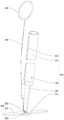
FIG. 1 is a schematic view showing a plate thickness measuring tool according to an embodiment of the present invention, when a reference plate is not opened;
FIG. 2 is an exploded view of the gauge tool of FIG. 1;
FIG. 3 is a schematic view of the plate thickness measuring tool shown in FIG. 1 after opening the reference plate;
fig. 4 is a simplified flowchart of the sheet thickness measurement.
The measuring device comprises a measuring scale 100, a measuring rod 110, a buckling hole 111, a hiding groove 112, a pointing head 120, a blocking part 121, an elastic clamping foot 122 and an inserting part 123;
a pin 200;
a reference plate 300, a plate body 310, a crank arm 320;
a tested plate 500 and a measuring hole 510.
Detailed Description
Reference will now be made in detail to embodiments of the present invention, examples of which are illustrated in the accompanying drawings, wherein like or similar reference numerals refer to the same or similar elements or elements having the same or similar function throughout. The embodiments described below with reference to the accompanying drawings are illustrative only for the purpose of explaining the present invention, and are not to be construed as limiting the present invention.
In the description of the present invention, it should be understood that the orientation or positional relationship referred to in the description of the orientation, such as the upper, lower, front, rear, left, right, etc., is based on the orientation or positional relationship shown in the drawings, and is only for convenience of description and simplification of description, and does not indicate or imply that the device or element referred to must have a specific orientation, be constructed and operated in a specific orientation, and thus, should not be construed as limiting the present invention.
In the description of the present invention, the meaning of a plurality of means is one or more, the meaning of a plurality of means is two or more, and larger, smaller, larger, etc. are understood as excluding the number, and larger, smaller, inner, etc. are understood as including the number. If the first and second are described for the purpose of distinguishing technical features, they are not to be understood as indicating or implying relative importance or implicitly indicating the number of technical features indicated or implicitly indicating the precedence of the technical features indicated.
In the description of the present invention, unless otherwise explicitly limited, terms such as arrangement, installation, connection and the like should be understood in a broad sense, and those skilled in the art can reasonably determine the specific meanings of the above terms in the present invention in combination with the specific contents of the technical solutions.
Referring to fig. 1 to 3, a plate thickness measuring tool according to a first aspect of the present invention includes a measuring scale 100, a pin 200, a reference plate 300 and a pulling rope 400, wherein one end of the measuring scale 100 is provided with a stopper 121, the pin 200 is connected to one end of the measuring scale 100, the pin 200 and the stopper 121 are spaced apart from each other, the reference plate 300 includes a plate body 310 and a crank 320, one end of the crank 320 is connected to the plate body 310, the other end of the crank 320 is offset from a plane where the plate body 310 is located, the other end of the crank 320 is rotatably connected to the pin 200, a side of the reference plate 300 facing the measuring scale 100 is perpendicular to the measuring scale 100 when the reference plate 300 abuts against the stopper 121, and one end of the measuring scale 100 or one end of the pin 200 is connected to the pulling rope 400.
The pin 200 is spaced apart from the stopper 121, and the reference plate 300 can swing until the stopper 121 abuts against the reference plate.
The pin 200 is connected to one end of a stop pin on the measurement scale 100. In some embodiments, the pin 200 is fixedly attached to the measurement scale 100, such as integrally formed, welded, threaded. The cord piece itself is somewhat flexible, bendable, and after the measuring scale 100 has passed down over the board 500 to be measured, the measuring scale 100 can also be turned over, with the end of the connecting pull cord 400 on the measuring scale 100 facing up. In some embodiments, the pin 200 may be rotatably coupled to the measuring ruler 100.
The plate thickness measuring tool provided by the embodiment of the invention at least has the following beneficial effects: only one person needs to operate above the measured plate 500, a tool is inserted into the measuring hole 510 above the measured plate 500, and the hinged ends of the measuring scale 100 and the reference plate 300 are inserted into the measuring hole 510; one end of the crank arm 320 is deviated from the plane of the plate body 310, the reference plate 300 swings open under its own weight after passing downward over the measured plate 500, the side of the reference plate 300 facing the measuring scale 100 is vertical to the measuring scale 100 when the reference plate 300 abuts against the stopper 121, and the side of the reference plate 300 facing the measuring scale 100 can be used as a corresponding structure of the zero scale of the measuring scale 100; one end of the pulling rope 400 is connected with the measuring scale 100 or the pin shaft 200, and the other end of the pulling rope 400 is a free end; after the thickness of the measured plate 500 is measured, the free end of the pulling rope 400 is pulled, and the measuring scale 100 also passes through the measured plate 500 downwards, so that the measuring scale 100 deflects under the pendant of the pulling rope 400, the hinged ends of the measuring scale 100 and the reference plate 300 are turned upwards, and the reference plate 300 is correspondingly folded with the measuring scale 100 under the action of self gravity; the tool after closing can be pulled up over the metering hole 510 with the pull cord 400; therefore, the single-person simple measurement is realized, the manpower is liberated, and the measurement configuration personnel are reduced.
In the production of the plate thickness measuring tool, the measuring scale 100 and the reference plate 300 are produced, and the measuring scale 100 and the reference plate 300 are hinged to each other by the pin 200. The pin 200 may be fixedly connected to the measuring scale 100, for example, the pin is a spline, or the pin is in threaded connection with the measuring scale 100); pin 200) and measuring scale 100) may also be rotatably connected, measuring scale 100) being rotatable relative to pin 200). The measuring scale 100) is hinged with the reference plate 300), the reference plate is opened to the vertical state relative to the measuring scale 100), the corresponding position of zero scale is determined, a plurality of scale marks are recorded on the measuring scale 100), and the corresponding numerical values are marked.
Referring to fig. 1 to 4, a sheet thickness measuring method according to an embodiment of a second aspect of the present invention includes the steps of:
inserting a tool, wherein an operator is positioned above the measured plate 500, inserting the plate thickness measuring tool into the measuring hole 510 of the measured plate 500 from top to bottom, inserting the hinged end of the measuring scale 100 and the reference plate 300 into the measuring hole 510, holding the upper end of the measuring scale 100 by the operator, and preventing the free end of the traction rope 400 from falling into the measuring hole 510;
the reference is attached, the reference plate 300 swings and opens under the action of self gravity after passing over the measured plate 500, the measuring scale 100 is pulled upwards, the side surface of the reference plate 300 facing the measuring scale 100 is abutted against the lower end surface of the measured plate 500, the reference plate 300 is abutted against the blocking part 121 on the measuring scale 100, and the side surface of the reference plate 300 facing the measuring scale 100 is vertical to the measuring scale 100;
reading, wherein the upper end face of the measured plate 500 corresponds to a scale of the measuring scale 100, and the reading of the scale corresponds to the thickness value of the measured plate 500;
preparing before drawing the tool, holding the free end of the traction rope 400 by an operator, continuously turning the measuring scale 100 downwards, swinging the measuring scale 100 after the measuring scale 100 passes through the measured plate 500, drawing and drawing one end of the measuring scale 100, which is hinged with the reference plate 300, by the traction rope 400, and upwards drawing the hinged end, and folding the reference plate 300 towards the measuring scale 100;
the tool is retracted and the operator pulls the pull cord 400, the measuring tape 100 and the reference plate 300 through the measuring hole 510 from bottom to top.
The plate thickness measuring method provided by the embodiment of the invention has at least the following beneficial effects: only need operate alone in being surveyed board 500 tops, realize single simple and easy measurement, liberation manpower reduces and measures the configuration personnel.
In some embodiments of the present invention, in the reference applying step, after the reference plate 300 passes over the measured plate 500, the rotating or shaking tool swings the reference plate 300 open. The reference plate 300 is deviated from the rotation axis position of the pin shaft, and when rotated, it is given a centrifugal action to eccentrically swing and open the reference plate 300.
Referring to fig. 1 to 3, in some embodiments of the present invention, the measuring ruler 100 includes a measuring rod 110 and a pointing head 120, the measuring rod 110 is detachably connected to the pointing head 120, and a stopper 121 is disposed at an end of the pointing head 120 away from the measuring rod 110. The measuring rod 110 and the pointing head 120 are convenient to disassemble and assemble, and are convenient to store and transport after being disassembled; the measuring stick 110 is detachable, the measuring stick 110 can have a plurality of different measuring range specifications, and the measuring stick 110 can be made as long as possible. The tool insertion step is also preceded by a range exchange step, in which the measuring rod 110 with a larger or smaller range is exchanged. In some fields, the measured plate 500 is thicker or thinner, and the measuring rod 110 is replaced with a longer or shorter one.
In some embodiments of the present invention, the measuring rod 110 is provided with a plurality of measuring rods 110, and the plurality of measuring rods 110 correspond to different measuring ranges respectively.
In some embodiments of the invention, the measurement ruler 100 is snap-fit or threaded with the pointing head 120.
Referring to fig. 1 to 3, in some embodiments of the present invention, one of the measuring tape 100 and the pointing head 120 is provided with an elastic clip 122, and the other is provided with a fastening hole 111 for connecting the elastic clip 122. The snap-fit connection, the measuring scale 100 and the pointing head 120 are very convenient to disassemble and assemble.
Referring to fig. 1 to 3, in some embodiments of the present invention, the measuring rod 110 is a hollow rod, the pointing head 120 is provided with an insertion portion 123 for inserting the measuring rod 110, the measuring rod 110 is provided with a fastening hole 111 on a peripheral wall, and the insertion portion 123 is provided with an elastic fastening pin 122. The elastic clamping pin 122 can be pressed on the outer side of the measuring rod 110, so that the elastic clamping pin 122 is separated from the clamping hole 111, and the elastic clamping pin 122 is convenient to unlock in the arrangement. In the span changing step, the elastic latch 122 is pressed outside the measuring rod 110 to drive the elastic latch 122 to disengage from the fastening hole 111.
Referring to fig. 1 to 3, in some embodiments of the present invention, the other end of the pull-cord 400 is provided with a pull-tab 410. During the tool insertion, datum abutment and reading steps, the pull ring 410 is hooked over the operator's finger or the stud of an external object. In the use of the tool, the free end of the pulling rope 400 can be hung on the finger of an operator, and the pulling rope 400 does not need to be arranged and pulled with much mind when the pulling rope 400 is not required to be operated.
The pull ring 410 and the pull rope 400 may be integrally formed, such as being a rope member made of a material of the pull ring 410. The pull ring 410 and the pull rope 400 may be formed separately and then connected together, such as the pull rope 400 formed by rope member material, and the pull ring 410 may be a metal ring. The hauling rope 400 may be made of existing fibers such as nylon, polyester, etc., or may be a steel wire.
Referring to fig. 1 to 3, in some embodiments of the present invention, a hidden groove 112 is formed on a circumferential wall of the measuring ruler 100, and a middle portion of the pulling string 400 may be received in the hidden groove 112. The middle portion of the pull string 400 is received in the hidden slot 112 during the tool insertion, datum abutment, reading and tool pre-retraction preparation steps. Especially, when the measuring hole 510 is small, the pulling rope 400 can be well prevented from being clamped and pressed, and the pulling rope 400 is prevented from being worn. In the use of the tool, the free end of the pulling rope 400 can be hung on the finger of an operator, and the pulling rope 400 does not need to be arranged and pulled with much mind when the pulling rope 400 is not required to be operated.
Referring to fig. 1-3, in some embodiments of the invention, a pin 200 is rotatably coupled to the measurement scale 100 and a pull cord 400 is coupled to the pin 200. In the preparation step before the tool is retracted, the measuring scale 100 and the reference plate 300 are rotated with respect to the pin 200. In the upset of dipperstick 100 and benchmark board 300, mainly the round pin axle 200 rotates relatively, reduces the distortion of haulage rope 400 junction and turns, and haulage rope 400 junction can not too fast mechanical fatigue, breakage, can effectively promote life.
Referring to fig. 1 to 3, in some embodiments of the invention, two reference plates 300 are provided, and the measuring scale 100 is provided between the two reference plates 300. In the reference abutment step, the two reference plates 300 abut against the lower end surface of the board 500 to be measured. Lean on and is leaned on the board 500 lower extreme face examination of being surveyed, two benchmark boards 300 all get to lean on and lean on the board 500 of being surveyed, especially when measuring hole 510 is great, can judge fast that benchmark board 300 pastes and leans on in place, avoid dipperstick 100 skew misalignment, set up the dipperstick 100 at the intermediate position.
The embodiments of the present invention have been described in detail with reference to the accompanying drawings, but the present invention is not limited to the above embodiments, and various changes can be made within the knowledge of those skilled in the art without departing from the gist of the present invention.
Claims (7)
1. The plate thickness measuring method is characterized in that a plate thickness measuring tool comprises a measuring scale (100), a pin shaft (200), a reference plate (300) and a traction rope (400), a blocking portion (121) is arranged at one end of the measuring scale (100), one end of the measuring scale (100) is connected with the pin shaft (200), the pin shaft (200) and the blocking portion (121) are arranged at intervals, the reference plate (300) comprises a plate body (310) and a crank arm (320), one end of the crank arm (320) is connected with the plate body (310), the other end of the crank arm (320) deviates from a plane where the plate body (310) is located, the other end of the crank arm (320) is rotatably connected with the pin shaft (200), when the reference plate (300) abuts against the blocking portion (121), the side face, facing the measuring scale (100), of the reference plate (300) is perpendicular to the measuring scale (100), one end of the measuring scale (100) or the pin shaft (200) is connected with one end of the traction rope (400) The plate thickness measuring method comprises the following steps:
inserting a tool, namely inserting a plate thickness measuring tool into a measuring hole (510) of a measured plate (500) from top to bottom, inserting one end of a measuring scale (100) and one end of a reference plate (300) which are hinged into the measuring hole (510) first, holding the upper end of the measuring scale (100), and preventing the free end of a traction rope (400) from falling into the measuring hole (510);
the reference plate (300) is attached to the measuring scale, the measuring scale (100) is lifted upwards after the reference plate (300) crosses the measured plate (500) and is opened in a deflected mode under the action of self gravity, the side face, facing the measuring scale (100), of the reference plate (300) is abutted to the lower end face of the measured plate (500), the reference plate (300) is abutted to a blocking part (121) on the measuring scale (100), and the side face, facing the measuring scale (100), of the reference plate (300) is vertical to the measuring scale (100);
reading, wherein the upper end face of the measured plate (500) corresponds to a scale of the measuring scale (100), and the scale reading corresponds to the thickness value of the measured plate (500);
preparing before drawing the tool, holding the free end of the traction rope (400), continuously moving the measuring scale (100) downwards, swinging and rotating the measuring scale (100) after the measuring scale (100) crosses the measured plate (500), pulling and drawing the hinged ends of the measuring scale (100) and the reference plate (300) by the traction rope (400), and moving the hinged ends upwards, and folding the reference plate (300) towards the measuring scale (100);
and (5) recovering the tool, lifting the traction rope (400), and enabling the measuring scale (100) and the reference plate (300) to penetrate through the measuring hole (510) from bottom to top.
2. The plate thickness measuring method according to claim 1, wherein the measuring rule (100) includes a measuring rod (110) and a pointing head (120), the measuring rod (110) is detachably connected to the pointing head (120), and the tool inserting step is preceded by a span changing step of changing the measuring rod (110) having a larger or smaller span.
3. The plate thickness measuring method according to claim 2, wherein the measuring rod (110) is a hollow rod, the indicator (120) is provided with an insertion portion (123) for inserting the measuring rod (110), the insertion portion (123) is provided with an elastic locking leg (122), the measuring rod (110) is provided with a locking hole (111) for connecting the elastic locking leg (122) on a peripheral wall, and in the range changing step, the elastic locking leg (122) is pressed outside the measuring rod (110) to drive the elastic locking leg (122) to be separated from the locking hole (111).
4. A method for measuring sheet thickness according to claim 1, wherein a free end of said pulling rope (400) is provided with a pull ring (410), and said pull ring (410) is hooked on a finger of an operator or a nail of an external object in said tool inserting, reference attaching and reading steps.
5. The method of measuring a plate thickness according to claim 1, wherein a hidden groove (112) is provided on a peripheral wall of the measuring rule (100), and a central portion of the pulling rope (400) is received in the hidden groove (112) in the steps of tool insertion, reference abutment, reading, and preparation before tool retraction.
6. The plate thickness measuring method according to claim 1, wherein two reference plates (300) are provided, the measuring scale (100) is provided between the two reference plates (300), and in the reference abutting step, the two reference plates (300) abut against a lower end surface of the plate under test (500).
7. A method for measuring sheet thickness according to claim 1, wherein said measuring rule (100) and said reference plate (300) are each a rotatably attached pin (200) to which a pull cord (400) is attached to said pin (200), and wherein said measuring rule (100) and said reference plate (300) are rotated relative to said pin (200) in said tool pre-retraction preparation step.
Priority Applications (1)
| Application Number | Priority Date | Filing Date | Title |
|---|---|---|---|
| CN202010760251.5A CN111981944B (en) | 2020-07-31 | 2020-07-31 | Method for measuring sheet thickness |
Applications Claiming Priority (1)
| Application Number | Priority Date | Filing Date | Title |
|---|---|---|---|
| CN202010760251.5A CN111981944B (en) | 2020-07-31 | 2020-07-31 | Method for measuring sheet thickness |
Publications (2)
| Publication Number | Publication Date |
|---|---|
| CN111981944A CN111981944A (en) | 2020-11-24 |
| CN111981944B true CN111981944B (en) | 2022-03-29 |
Family
ID=73445682
Family Applications (1)
| Application Number | Title | Priority Date | Filing Date |
|---|---|---|---|
| CN202010760251.5A Active CN111981944B (en) | 2020-07-31 | 2020-07-31 | Method for measuring sheet thickness |
Country Status (1)
| Country | Link |
|---|---|
| CN (1) | CN111981944B (en) |
Citations (9)
| Publication number | Priority date | Publication date | Assignee | Title |
|---|---|---|---|---|
| JP2013195412A (en) * | 2012-03-23 | 2013-09-30 | Mitsubishi Heavy Ind Ltd | Plate thickness measurement device and plate thickness measurement method |
| CN205245948U (en) * | 2015-12-11 | 2016-05-18 | 刘怡静 | Concrete floor pours thickness inspection light instrument |
| CN105953698A (en) * | 2016-07-18 | 2016-09-21 | 中建八局第三建设有限公司 | Floor thickness measuring tool and measuring method |
| JP2017161414A (en) * | 2016-03-10 | 2017-09-14 | 京セラ株式会社 | Thickness measuring device |
| CN207963712U (en) * | 2018-03-26 | 2018-10-12 | 浙江省三建建设集团有限公司 | A kind of concrete slab thickness detector |
| CN209069173U (en) * | 2018-09-07 | 2019-07-05 | 安徽省建筑工程质量监督检测站 | It is a kind of for detecting the tooling of thickness of concrete floor |
| CN110763105A (en) * | 2019-09-18 | 2020-02-07 | 镇江新区建设工程质量中心试验室 | Floor thickness damage detection method |
| CN210374915U (en) * | 2019-08-02 | 2020-04-21 | 嘉兴市春秋建设工程检测中心有限责任公司 | Floor thickness detection device of convenient operation |
| CN212779018U (en) * | 2020-07-31 | 2021-03-23 | 华润建筑有限公司 | Plate thickness measuring tool |
Family Cites Families (1)
| Publication number | Priority date | Publication date | Assignee | Title |
|---|---|---|---|---|
| CN203687831U (en) * | 2013-12-17 | 2014-07-02 | 中建八局第四建设有限公司 | Measuring subassembly for measuring thickness of floor plate |
-
2020
- 2020-07-31 CN CN202010760251.5A patent/CN111981944B/en active Active
Patent Citations (9)
| Publication number | Priority date | Publication date | Assignee | Title |
|---|---|---|---|---|
| JP2013195412A (en) * | 2012-03-23 | 2013-09-30 | Mitsubishi Heavy Ind Ltd | Plate thickness measurement device and plate thickness measurement method |
| CN205245948U (en) * | 2015-12-11 | 2016-05-18 | 刘怡静 | Concrete floor pours thickness inspection light instrument |
| JP2017161414A (en) * | 2016-03-10 | 2017-09-14 | 京セラ株式会社 | Thickness measuring device |
| CN105953698A (en) * | 2016-07-18 | 2016-09-21 | 中建八局第三建设有限公司 | Floor thickness measuring tool and measuring method |
| CN207963712U (en) * | 2018-03-26 | 2018-10-12 | 浙江省三建建设集团有限公司 | A kind of concrete slab thickness detector |
| CN209069173U (en) * | 2018-09-07 | 2019-07-05 | 安徽省建筑工程质量监督检测站 | It is a kind of for detecting the tooling of thickness of concrete floor |
| CN210374915U (en) * | 2019-08-02 | 2020-04-21 | 嘉兴市春秋建设工程检测中心有限责任公司 | Floor thickness detection device of convenient operation |
| CN110763105A (en) * | 2019-09-18 | 2020-02-07 | 镇江新区建设工程质量中心试验室 | Floor thickness damage detection method |
| CN212779018U (en) * | 2020-07-31 | 2021-03-23 | 华润建筑有限公司 | Plate thickness measuring tool |
Also Published As
| Publication number | Publication date |
|---|---|
| CN111981944A (en) | 2020-11-24 |
Similar Documents
| Publication | Publication Date | Title |
|---|---|---|
| CN212779018U (en) | Plate thickness measuring tool | |
| CN111981944B (en) | Method for measuring sheet thickness | |
| CN208026283U (en) | Measuring for verticality falls device with smart wire | |
| CN210513135U (en) | Ruler for detecting quality of constructional engineering | |
| CN208966326U (en) | A kind of elevation angle bolthole drill hole inclination measuring tool | |
| CN206818728U (en) | Test card | |
| CN209673573U (en) | A kind of strength of glass test device | |
| CN209131664U (en) | Ruler is used in a kind of detection of construction engineering quality | |
| CN214749979U (en) | Concrete strength on-site detector | |
| CN208563062U (en) | A kind of digital smoothness measuring equipment | |
| CN217980301U (en) | Foldable efficient simple verticality detection ruler | |
| CN206514741U (en) | A kind of direct-reading slab thickness measuring scale | |
| CN217424384U (en) | Measuring marker post | |
| CN114034285B (en) | High-voltage line tower safety inspection equipment based on sensor | |
| CN209085587U (en) | Spline wedge angle symmetry measuring device | |
| CN214845007U (en) | Portable detection hammer for constructional engineering | |
| CN208733694U (en) | Grout pile bottom dirt slag thickness detection apparatus | |
| CN220039446U (en) | Straightness detection device hangs down | |
| CN208884327U (en) | A kind of construction of the highway road surface checking device | |
| CN205981035U (en) | Scissors form enlarged footing anchor eye inside diameter measurement ware | |
| CN220794237U (en) | Engineering quality detection device convenient to operate | |
| CN212747627U (en) | Button interval rechecking device of twisting machine | |
| CN202437140U (en) | Auxiliary portable armrest for lie detector | |
| CN219978028U (en) | Dangerous house identification device after earthquake | |
| CN213688370U (en) | Building engineering straightness detection device that hangs down |
Legal Events
| Date | Code | Title | Description |
|---|---|---|---|
| PB01 | Publication | ||
| PB01 | Publication | ||
| SE01 | Entry into force of request for substantive examination | ||
| SE01 | Entry into force of request for substantive examination | ||
| GR01 | Patent grant | ||
| GR01 | Patent grant |