CN111958358A - Workpiece end face grinding and polishing platform for multi-form grinding - Google Patents
Workpiece end face grinding and polishing platform for multi-form grinding Download PDFInfo
- Publication number
- CN111958358A CN111958358A CN202010834522.7A CN202010834522A CN111958358A CN 111958358 A CN111958358 A CN 111958358A CN 202010834522 A CN202010834522 A CN 202010834522A CN 111958358 A CN111958358 A CN 111958358A
- Authority
- CN
- China
- Prior art keywords
- grinding
- polishing
- fixedly connected
- supporting
- plate
- Prior art date
- Legal status (The legal status is an assumption and is not a legal conclusion. Google has not performed a legal analysis and makes no representation as to the accuracy of the status listed.)
- Granted
Links
- 238000005498 polishing Methods 0.000 title claims abstract description 99
- 238000000227 grinding Methods 0.000 title claims abstract description 79
- 238000009837 dry grinding Methods 0.000 claims abstract description 59
- 238000001238 wet grinding Methods 0.000 claims abstract description 46
- 239000007921 spray Substances 0.000 claims abstract description 40
- 230000005540 biological transmission Effects 0.000 claims abstract description 15
- 239000002351 wastewater Substances 0.000 claims abstract description 15
- 238000005507 spraying Methods 0.000 claims description 30
- 239000000314 lubricant Substances 0.000 claims description 29
- 238000013016 damping Methods 0.000 claims description 7
- XLYOFNOQVPJJNP-UHFFFAOYSA-N water Substances O XLYOFNOQVPJJNP-UHFFFAOYSA-N 0.000 claims description 7
- 238000010276 construction Methods 0.000 description 4
- 238000010586 diagram Methods 0.000 description 4
- 239000000428 dust Substances 0.000 description 3
- 238000000034 method Methods 0.000 description 3
- 238000013459 approach Methods 0.000 description 2
- 238000009434 installation Methods 0.000 description 2
- 238000003754 machining Methods 0.000 description 2
- 238000012545 processing Methods 0.000 description 2
- 238000007792 addition Methods 0.000 description 1
- 230000009286 beneficial effect Effects 0.000 description 1
- 238000004891 communication Methods 0.000 description 1
- 230000001788 irregular Effects 0.000 description 1
- 238000012986 modification Methods 0.000 description 1
- 230000004048 modification Effects 0.000 description 1
- 238000006467 substitution reaction Methods 0.000 description 1
- 239000000725 suspension Substances 0.000 description 1
Images


Classifications
-
- B—PERFORMING OPERATIONS; TRANSPORTING
- B24—GRINDING; POLISHING
- B24B—MACHINES, DEVICES, OR PROCESSES FOR GRINDING OR POLISHING; DRESSING OR CONDITIONING OF ABRADING SURFACES; FEEDING OF GRINDING, POLISHING, OR LAPPING AGENTS
- B24B7/00—Machines or devices designed for grinding plane surfaces on work, including polishing plane glass surfaces; Accessories therefor
- B24B7/10—Single-purpose machines or devices
- B24B7/16—Single-purpose machines or devices for grinding end-faces, e.g. of gauges, rollers, nuts, piston rings
-
- B—PERFORMING OPERATIONS; TRANSPORTING
- B24—GRINDING; POLISHING
- B24B—MACHINES, DEVICES, OR PROCESSES FOR GRINDING OR POLISHING; DRESSING OR CONDITIONING OF ABRADING SURFACES; FEEDING OF GRINDING, POLISHING, OR LAPPING AGENTS
- B24B27/00—Other grinding machines or devices
- B24B27/0076—Other grinding machines or devices grinding machines comprising two or more grinding tools
-
- B—PERFORMING OPERATIONS; TRANSPORTING
- B24—GRINDING; POLISHING
- B24B—MACHINES, DEVICES, OR PROCESSES FOR GRINDING OR POLISHING; DRESSING OR CONDITIONING OF ABRADING SURFACES; FEEDING OF GRINDING, POLISHING, OR LAPPING AGENTS
- B24B27/00—Other grinding machines or devices
- B24B27/02—Bench grinders
-
- B—PERFORMING OPERATIONS; TRANSPORTING
- B24—GRINDING; POLISHING
- B24B—MACHINES, DEVICES, OR PROCESSES FOR GRINDING OR POLISHING; DRESSING OR CONDITIONING OF ABRADING SURFACES; FEEDING OF GRINDING, POLISHING, OR LAPPING AGENTS
- B24B41/00—Component parts such as frames, beds, carriages, headstocks
- B24B41/02—Frames; Beds; Carriages
-
- B—PERFORMING OPERATIONS; TRANSPORTING
- B24—GRINDING; POLISHING
- B24B—MACHINES, DEVICES, OR PROCESSES FOR GRINDING OR POLISHING; DRESSING OR CONDITIONING OF ABRADING SURFACES; FEEDING OF GRINDING, POLISHING, OR LAPPING AGENTS
- B24B41/00—Component parts such as frames, beds, carriages, headstocks
- B24B41/06—Work supports, e.g. adjustable steadies
-
- B—PERFORMING OPERATIONS; TRANSPORTING
- B24—GRINDING; POLISHING
- B24B—MACHINES, DEVICES, OR PROCESSES FOR GRINDING OR POLISHING; DRESSING OR CONDITIONING OF ABRADING SURFACES; FEEDING OF GRINDING, POLISHING, OR LAPPING AGENTS
- B24B47/00—Drives or gearings; Equipment therefor
- B24B47/02—Drives or gearings; Equipment therefor for performing a reciprocating movement of carriages or work- tables
- B24B47/08—Drives or gearings; Equipment therefor for performing a reciprocating movement of carriages or work- tables by mechanical gearing combined with fluid systems
-
- B—PERFORMING OPERATIONS; TRANSPORTING
- B24—GRINDING; POLISHING
- B24B—MACHINES, DEVICES, OR PROCESSES FOR GRINDING OR POLISHING; DRESSING OR CONDITIONING OF ABRADING SURFACES; FEEDING OF GRINDING, POLISHING, OR LAPPING AGENTS
- B24B47/00—Drives or gearings; Equipment therefor
- B24B47/10—Drives or gearings; Equipment therefor for rotating or reciprocating working-spindles carrying grinding wheels or workpieces
- B24B47/12—Drives or gearings; Equipment therefor for rotating or reciprocating working-spindles carrying grinding wheels or workpieces by mechanical gearing or electric power
-
- B—PERFORMING OPERATIONS; TRANSPORTING
- B24—GRINDING; POLISHING
- B24B—MACHINES, DEVICES, OR PROCESSES FOR GRINDING OR POLISHING; DRESSING OR CONDITIONING OF ABRADING SURFACES; FEEDING OF GRINDING, POLISHING, OR LAPPING AGENTS
- B24B55/00—Safety devices for grinding or polishing machines; Accessories fitted to grinding or polishing machines for keeping tools or parts of the machine in good working condition
- B24B55/06—Dust extraction equipment on grinding or polishing machines
-
- Y—GENERAL TAGGING OF NEW TECHNOLOGICAL DEVELOPMENTS; GENERAL TAGGING OF CROSS-SECTIONAL TECHNOLOGIES SPANNING OVER SEVERAL SECTIONS OF THE IPC; TECHNICAL SUBJECTS COVERED BY FORMER USPC CROSS-REFERENCE ART COLLECTIONS [XRACs] AND DIGESTS
- Y02—TECHNOLOGIES OR APPLICATIONS FOR MITIGATION OR ADAPTATION AGAINST CLIMATE CHANGE
- Y02P—CLIMATE CHANGE MITIGATION TECHNOLOGIES IN THE PRODUCTION OR PROCESSING OF GOODS
- Y02P70/00—Climate change mitigation technologies in the production process for final industrial or consumer products
- Y02P70/10—Greenhouse gas [GHG] capture, material saving, heat recovery or other energy efficient measures, e.g. motor control, characterised by manufacturing processes, e.g. for rolling metal or metal working
Abstract
The invention relates to the technical field of workpiece end face grinding and polishing, in particular to a workpiece end face grinding and polishing platform for multi-form grinding and polishing, which comprises a grinding and polishing supporting platform, a dry grinding and polishing supporting frame, a waste water collecting box, a connecting rod extending out of a spray pipe, a spray pipe extending out of the spray pipe, a dry grinding and polishing component, a wet grinding and polishing component and an adjusting and supporting polishing platform, and has the advantage of switching of multiple forms of grinding and polishing, wherein the dry grinding and polishing supporting frame is fixedly connected at the upper end of the grinding and polishing supporting platform, the dry grinding and polishing component is fixedly connected at the upper end of the dry grinding and polishing supporting frame, the wet grinding and polishing component is fixedly connected on the dry grinding and polishing component, the two connecting rods extending out of the spray pipe are both slidably connected in the dry grinding and polishing supporting platform, the two connecting rods extending out of the spray pipe are both rotatably connected with the waste water collecting box extending out of the spray, the adjusting supporting grinding table is in meshing transmission with the grinding and polishing supporting platform.
Description
Technical Field
The invention relates to the technical field of workpiece end face grinding and polishing, in particular to a workpiece end face grinding and polishing platform for multi-form grinding.
Background
In the technical field of machining, a workpiece needs to be polished on the machined end face after machining is finished so as to improve the precision of the end face, and a polishing workbench is industrial dust removal equipment integrating a workbench and a dust remover. The polishing workbench is suitable for small and medium-sized fine processing and irregular part processing working conditions. Under the prerequisite that does not interfere workman daily operation, the fine dust of suspension can effectively be catched to the workstation of polishing, provides clean healthy operational environment for the workman, but the platform is thrown to the mill commonly used and can only carry out the polishing of a form usually, often still need change the apparatus of polishing, is not very convenient to carry out the work of polishing.
Disclosure of Invention
The invention aims to provide a workpiece end face grinding and polishing platform for multi-form grinding and polishing, which has the advantage of switching among various forms of grinding and polishing.
The purpose of the invention is realized by the following technical scheme:
a workpiece end face grinding and polishing platform for multiform polishing comprises a grinding and polishing supporting platform, a dry grinding and polishing supporting frame, a waste water collecting box, a connecting rod extending out of a spraying pipe, a stretching spraying pipe, a dry grinding and polishing assembly, a wet grinding and polishing assembly and an adjusting and supporting grinding platform, wherein the dry grinding and polishing supporting frame is fixedly connected to the upper end of the grinding and polishing supporting platform;
the grinding and polishing support platform comprises an upper support plate, a support table sliding support plate, support legs, sliding rods, damping springs and bottom anti-skidding blocks, wherein the support table sliding support plate is fixedly connected to the upper support plate;
the dry grinding support frame comprises a support frame, an upper support beam and sliding chutes, the support frame is fixedly connected to the upper end of the upper support plate, the upper support beam is fixedly connected to the support frame, and the two sliding chutes are arranged on the support frame;
the waste water collecting box comprises a collecting box, supporting edges and track lifting plates, the two supporting edges are respectively and fixedly connected to the front end and the rear end of the collecting box, the two track lifting plates are respectively and fixedly connected to the right ends of the two supporting edges, and the supporting edges are fixedly connected to the upper supporting plate;
the connecting rod of the extending spraying pipe comprises a pushing motor, a pushing screw rod, a connecting rod and connecting grooves, the pushing screw rod is fixedly connected to an output shaft of the pushing motor, the connecting rod and the pushing screw rod are in threaded transmission, the two connecting grooves are both arranged on the connecting rod, the two pushing motors are both fixedly connected to the supporting frame, and the two connecting rods are respectively connected in the two sliding grooves in a sliding manner;
the extension spraying pipe comprises a rotary spraying box, spraying pipes, a driving gear, an adjusting bolt, an adjusting gear and spray heads, wherein the spraying pipes are rotatably connected to the rotary spraying box;
the dry grinding and polishing assembly comprises a grinding assembly supporting frame, a dry grinding motor, a dry grinding wheel and a wet die assembly mounting groove, the dry grinding motor is fixedly connected to the grinding assembly supporting frame, the grinding assembly supporting frame is fixedly connected to the upper end of an upper supporting beam, the dry grinding wheel is fixedly connected to an output shaft of the dry grinding motor, and the wet die assembly mounting groove is formed in the grinding assembly supporting frame;
the wet grinding assembly comprises a wet grinding motor, a lubricant providing disc, a connecting hollow shaft and a wet grinding wheel, the lubricant providing disc is fixedly connected to the polishing and grinding assembly supporting frame, the wet grinding motor is fixedly connected to the lubricant providing disc, the connecting hollow shaft is fixedly connected to an output shaft of the wet grinding motor, the lubricant providing disc is communicated with the connecting hollow shaft, and the wet grinding wheel is fixedly connected to the lower end of the connecting hollow shaft;
the adjusting support polishing platform comprises a clamp supporting platform, limiting sliders, a lifting hydraulic rod, a clamp mounting plate, lifting inclined blocks, a moving motor connecting plate, a moving motor, a moving gear, a locking plate, a telescopic pipe and a tightening spring, wherein the two limiting sliders are fixedly connected to the lower end of the clamp supporting platform, the two limiting sliders are slidably connected between an upper supporting plate and a supporting platform sliding supporting plate, the lifting hydraulic rod is fixedly connected to the upper end of the clamp supporting platform, the clamp mounting plate is fixedly connected to the upper end of the lifting hydraulic rod, the two lifting inclined blocks are respectively and fixedly connected to the two limiting sliders, the moving motor connecting plate is fixedly connected to the limiting slider at the front end, the moving motor is slidably connected to a moving motor connecting plate, the locking plate is fixedly connected to the moving motor, the locking plate is slidably connected to the moving motor connecting plate, and the upper end and the lower end of the telescopic pipe, the tightening spring sleeve is arranged on the telescopic pipe, the upper end and the lower end of the tightening spring are fixedly connected to the locking plate and the mobile motor connecting plate respectively, the two lifting inclined blocks are connected to the two supporting edges in a sliding mode respectively, the two lifting inclined blocks are connected to the rail lifting plate in a sliding mode respectively, and the mobile gear is in meshing transmission with the meshing rack arranged on the upper supporting plate.
The workpiece end surface grinding and polishing platform for multi-form grinding has the beneficial effects that: the invention relates to a workpiece end face grinding and polishing platform for multi-form grinding, which is characterized in that a moving motor is started, a moving gear rotates, an adjusting support grinding table moves due to the meshing transmission of the moving gear and an upper support plate meshing rack, when two track lifting plates are contacted with two lifting inclined blocks, the adjusting support grinding table can ascend due to inclined planes, at the moment, a telescopic pipe extends, a tightening spring is stretched, the moving gear is always ensured to be always meshed with a meshing rack arranged on the upper support plate, the adjusting support grinding table moves to be positioned right above a waste water collecting box, the dry grinding and the wet grinding can be switched, two connecting rods are pushed out, four extending spray pipes are rotated out, a plurality of adjusting bolts are respectively rotated to drive a plurality of driving gears meshed with the adjusting gears, a plurality of spray pipes are rotated to drive a plurality of spray nozzles on the adjusting gears to rotate to adjust angles, and the spray pipes are externally connected with a water source, the plurality of nozzles spray water to clean the fixture supporting table.
Drawings
The invention is described in further detail below with reference to the accompanying drawings and specific embodiments.
In the description of the present invention, it should be noted that the terms "center", "longitudinal", "lateral", "up", "down", "front", "back", "left", "right", "top", "bottom", "inner", "outer" and "upright", etc., indicate orientations or positional relationships based on those shown in the drawings, and are only for convenience of description and simplicity of description, but do not indicate or imply that the referred device or element must have a specific orientation, be constructed and operated in a specific orientation, and thus, should not be construed as limiting the present invention.
In the description of the present invention, it should be noted that unless otherwise explicitly stated or limited, the terms "mounted," "connected," and "connected" are to be construed broadly, and may be, for example, fixedly connected, detachably connected, or integrally connected, directly or indirectly connected through an intermediate medium, and may be a communication between two members. The specific meanings of the above terms in the present invention can be understood in specific cases to those skilled in the art.
In addition, in the description of the present invention, the meaning of "a plurality", and "a plurality" is two or more unless otherwise specified.
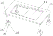
FIG. 1 is a schematic diagram of the overall construction of a multi-form polishing platform for polishing the end face of a workpiece;
FIG. 2 is a schematic structural view of the polishing support platform of the present invention;
FIG. 3 is a schematic diagram of the dry grinding carriage of the present invention;
FIG. 4 is a schematic view of the construction of the waste water collection tank of the present invention;
FIG. 5 is a schematic structural view of the extension shower attachment rod of the present invention;
FIG. 6 is a schematic view of the construction of the extended shower of the present invention;
FIG. 7 is a schematic diagram of the dry polishing assembly of the present invention;
FIG. 8 is a schematic diagram of the construction of the wet sanding assembly of the present invention;
FIG. 9 is a first schematic view of the adjustable support grinding table of the present invention;
FIG. 10 is a schematic view of the structure of the adjustable supporting and polishing table of the present invention
FIG. 11 is an enlarged view of the structure of the adjustable support grinding table of the present invention.
In the figure: grinding and polishing the supporting platform 1; an upper support plate 1-1; a support table sliding support plate 1-2; support legs 1-3; 1-4 of a sliding rod; 1-5 of a damping spring; 1-6 parts of bottom anti-skid blocks; dry grinding the support frame 2; a support frame 2-1; an upper support beam 2-2; 2-3 of a chute; a wastewater collection tank 3; a collection box 3-1; a support edge 3-2; a rail lifting plate 3-3; the spray pipe connecting rod 4 extends out; a push-out motor 4-1; pushing the screw rod 4-2; 4-3 of a connecting rod; 4-4 connecting grooves; extending out of the spray pipe 5; rotating the spraying box 5-1; 5-2 parts of a spray pipe; 5-3 of a driving gear; 5-4 of an adjusting bolt; 5-5 of an adjusting gear; 5-6 parts of a spray head; a dry grinding and polishing component 6; a polishing component support 6-1; a dry grinding motor 6-2; 6-3 parts of a dry grinding wheel; a wet die assembly mounting groove 6-4; a wet sanding assembly 7; wet grinding motor 7-1; a lubricant supply tray 7-2; connecting a hollow shaft 7-3; 7-4 parts of wet grinding wheel; adjusting the support polishing table 8; a jig support table 8-1; a limiting slide 8-2; lifting a hydraulic rod 8-3; 8-4, mounting a clamp; 8-5 of a lifting inclined block; a mobile motor connecting plate 8-6; 8-7 of a mobile motor; 8-8 parts of a movable gear; 8-9 of a locking plate; 8-10 of a telescopic pipe; the springs 8-11 are tightened.
Detailed Description
The present invention will be described in further detail with reference to the accompanying drawings.
The first embodiment is as follows:
the following describes the present embodiment with reference to fig. 1 to 11, and a workpiece end surface polishing platform for multiform polishing includes a polishing support platform 1, a dry polishing support frame 2, a wastewater collection tank 3, an extended shower connection rod 4, an extended shower 5, a dry polishing assembly 6, a wet polishing assembly 7, and an adjustment support polishing table 8, and is characterized in that: the dry grinding and polishing device comprises a dry grinding and polishing support frame 2, a dry grinding and polishing assembly 6, a wet grinding and polishing assembly 7, two extending spraying pipe connecting rods 4, two extending spraying pipes 5, a waste water collecting box 3, an adjusting support grinding table 8 and a grinding and polishing support platform 1, wherein the dry grinding and polishing assembly 2 is fixedly connected to the upper end of the dry grinding and polishing support frame 2;
installing a workpiece clamp on a clamp installation plate 8-4, clamping and installing a workpiece, starting a dry grinding motor 6-2, rotating a dry grinding wheel 6-3, adjusting the height of a lifting hydraulic rod 8-3 to adjust the lifting height of the workpiece, starting a moving motor 8-7, rotating a moving gear 8-8, enabling an adjusting support grinding table 8 to move due to the meshing transmission of the moving gear 8-8 and an upper support plate 1-1 meshing rack, enabling the adjusting support grinding table 8 to ascend due to an inclined plane when two track lifting plates 3-3 are contacted with two lifting inclined blocks 8-5, enabling an extension tube 8-10 to extend, stretching a tightening spring 8-11, always ensuring that the moving gear 8-8 is always meshed with a meshing rack arranged on the upper support plate 1-1, and enabling the adjusting support grinding table 8 to move right above a wastewater collection box 3, adding a lubricating agent into a lubricating agent providing disc 7-2, starting a wet grinding motor 7-1, rotating a wet grinding wheel 7-4, enabling the wet grinding wheel 7-4 to rotate, enabling the lubricating agent to flow out of a hollow connecting shaft 7-3 along with the rotation of a wet grinding wheel 7-4, adjusting the height of a lifting hydraulic rod 8-3 to enable a workpiece to approach the wet grinding wheel 7-4 to be subjected to wet grinding, enabling two pushing motors 4-1 to be started to enable two pushing screw rods 4-2 to rotate after the grinding is finished and enabling two connecting rods 4-3 to be pushed out, enabling four extending spraying pipes 5 to be rotated out, respectively rotating a plurality of adjusting bolts 5-4 to enable a plurality of adjusting gears 5-5 to rotate to drive a plurality of driving gears 5-3 meshed with the adjusting gears, enabling a plurality of spraying pipes 5-2 to rotate to drive a plurality of spray heads 5-6 on the adjusting gears to rotate to adjust angles, the spray pipe 5-2 is externally connected with an external water source, so that the plurality of spray heads 5-6 spray water to clean the fixture supporting table 8-1.
The second embodiment is as follows:
referring to fig. 1-11, the polishing support platform 1 includes an upper support plate 1-1, a support platform slide plate 1-2, and support legs 1-3, the support platform comprises sliding rods 1-4, damping springs 1-5 and bottom anti-skidding blocks 1-6, a support platform sliding support plate 1-2 is fixedly connected to an upper support plate 1-1, a plurality of support legs 1-3 are respectively and fixedly connected to four corners of the lower end of the upper support plate 1-1, a plurality of sliding rods 1-4 are respectively and slidably connected to the plurality of support legs 1-3, a plurality of sliding rods 1-4 are respectively and fixedly connected to the plurality of bottom anti-skidding blocks 1-6, the damping springs 1-5 are sleeved on the plurality of sliding rods 1-4, and a meshing rack is arranged on the lower portion of the front end of the upper support plate 1-1;
when a workpiece is installed, the sliding rods 1-4 slide into the supporting legs 1-3, and the damping springs 1-5 contract to remove the impact force generated when the workpiece is installed and place a damaged device.
The third concrete implementation mode:
the embodiment is described below with reference to fig. 1-11, wherein the dry grinding support frame 2 includes a support frame 2-1, an upper support beam 2-2 and a chute 2-3, the support frame 2-1 is fixedly connected to the upper end of the upper support plate 1-1, the upper support beam 2-2 is fixedly connected to the support frame 2-1, and the two chutes 2-3 are both disposed on the support frame 2-1;
the support frame 2-1 can prevent the scraps from splashing to the workers in the dry grinding process.
The fourth concrete implementation mode:
the present embodiment will be described with reference to fig. 1-11, wherein the wastewater collection tank 3 includes a collection tank 3-1, two support edges 3-2 and two rail lifting plates 3-3, the two support edges 3-2 are respectively and fixedly connected to the front and rear ends of the collection tank 3-1, the two rail lifting plates 3-3 are respectively and fixedly connected to the right ends of the two support edges 3-2, and the support edge 3-2 is fixedly connected to the upper support plate 1-1.
The fifth concrete implementation mode:
the present embodiment is described below with reference to fig. 1-11, wherein the connecting rod 4 extending out of the shower pipe includes a push-out motor 4-1, a push screw rod 4-2, a connecting rod 4-3 and a connecting groove 4-4, the push screw rod 4-2 is fixedly connected to an output shaft of the push-out motor 4-1, the connecting rod 4-3 and the push screw rod 4-2 are in screw transmission, two connecting grooves 4-4 are both arranged on the connecting rod 4-3, two push-out motors 4-1 are both fixedly connected to a supporting frame 2-1, and two connecting rods 4-3 are respectively slidably connected in two sliding grooves 2-3;
the two pushing motors 4-1 are started to enable the two pushing screw rods 4-2 to rotate, and the two connecting rods 4-3 slide out of the two sliding grooves 2-3 under the pushing of the threads.
The sixth specific implementation mode:
referring to fig. 1-11, the projecting spray pipe 5 includes a rotary spray box 5-1, a spray pipe 5-2, and a driving gear 5-3, the spray pipe 5-2 is rotatably connected to the rotary spray box 5-1, the meshing gear 5-3 is fixedly connected to the spray pipe 5-2, the driving gear 5-3 is in meshing transmission with the adjusting gear 5-5, the adjusting bolt 5-4 is rotatably connected to the rotary spray box 5-1, the adjusting gear 5-5 is fixedly connected to the adjusting bolt 5-4, the spray heads 5-6 are fixedly connected to the spray pipe 5-2, and the rotary spray boxes 5-1 are rotatably connected to the connecting grooves 4-4 respectively;
the two connecting rods 4-3 slide out, the rotary spraying boxes 5-1 are rotated, the adjusting bolts 5-4 are rotated to enable the adjusting gears 5-5 to rotate, the driving gears 5-3 meshed with the adjusting gears are driven to rotate, the spraying pipes 5-2 also rotate along with the adjusting gears, and the spraying heads 5-6 rotate to adjust the angle to clean the clamp supporting table 8-1.
The seventh embodiment:
the embodiment is described below with reference to fig. 1-11, wherein the dry grinding and polishing assembly 6 includes a grinding assembly holder 6-1, a dry grinding motor 6-2, a dry grinding wheel 6-3 and a wet mold assembly mounting groove 6-4, the dry grinding motor 6-2 is fixedly connected to the grinding assembly holder 6-1, the grinding assembly holder 6-1 is fixedly connected to the upper end of the upper support beam 2-2, the dry grinding wheel 6-3 is fixedly connected to the output shaft of the dry grinding motor 6-2, and the wet mold assembly mounting groove 6-4 is arranged on the grinding assembly holder 6-1;
and starting the dry grinding motor 6-2, and rotating the dry grinding wheel 6-3 to perform fine grinding.
The specific implementation mode is eight:
referring to fig. 1-11, the wet grinding assembly 7 includes a wet grinding motor 7-1, a lubricant supplying plate 7-2, a connecting hollow shaft 7-3 and a wet grinding wheel 7-4, the lubricant supplying plate 7-2 is fixedly connected to a polishing assembly support 6-1, the wet grinding motor 7-1 is fixedly connected to the lubricant supplying plate 7-2, the connecting hollow shaft 7-3 is fixedly connected to an output shaft of the wet grinding motor 7-1, the lubricant supplying plate 7-2 is communicated with the connecting hollow shaft 7-3, and the wet grinding wheel 7-4 is fixedly connected to the lower end of the connecting hollow shaft 7-3;
adding a lubricant into the lubricant supplying disc 7-2, enabling the lubricant to flow into the connecting hollow shaft 7-3, starting the wet grinding motor 7-1 to enable the wet grinding wheel 7-4 to rotate, enabling the lubricant to flow out from the connecting hollow shaft 7-3 along with the rotation of the wet grinding wheel 7-4 to enable the wet grinding wheel 7-4 to always have the lubricant, and carrying out rough grinding.
The specific implementation method nine:
the embodiment is described below with reference to fig. 1-11, the adjusting support grinding table 8 includes a clamp support table 8-1, a limiting slide 8-2, a lifting hydraulic rod 8-3, a clamp mounting plate 8-4, a lifting inclined block 8-5, a moving motor connecting plate 8-6, a moving motor 8-7, a moving gear 8-8, a locking plate 8-9, an extension tube 8-10 and a tightening spring 8-11, both limiting slides 8-2 are fixedly connected to the lower end of the clamp support table 8-1, both limiting slides 8-2 are slidably connected between the upper support plate 1-1 and the support table sliding support plate 1-2, the lifting hydraulic rod 8-3 is fixedly connected to the upper end of the clamp support table 8-1, and the clamp mounting plate 8-4 is fixedly connected to the upper end of the lifting hydraulic rod 8-3, two lifting inclined blocks 8-5 are respectively fixedly connected to two limiting sliders 8-2, a mobile motor connecting plate 8-6 is fixedly connected to the limiting slider 8-2 positioned at the front end, a mobile motor 8-7 is slidably connected to the mobile motor connecting plate 8-6, a locking plate 8-9 is fixedly connected to the mobile motor 8-7, the locking plate 8-9 is slidably connected to the mobile motor connecting plate 8-6, the upper and lower ends of a telescopic tube 8-10 are respectively fixedly connected to the locking plate 8-9 and the mobile motor connecting plate 8-6, a tightening spring 8-11 is sleeved on the telescopic tube 8-10, the upper and lower ends of the tightening spring 8-11 are respectively fixedly connected to the locking plate 8-9 and the mobile motor connecting plate 8-6, and the two lifting inclined blocks 8-5 are respectively slidably connected to two supporting edges 3-2, the two lifting inclined blocks 8-5 are respectively connected on the track lifting plates 3-3 in a sliding manner, and the moving gear 8-8 is in meshing transmission with the meshing rack arranged on the upper supporting plate 1-1.
The height of a workpiece can be adjusted by adjusting the lifting height of a lifting hydraulic rod 8-3, when the grinding form is changed, a moving motor 8-7 is started, a moving gear 8-8 rotates, the adjusting support grinding table 8 can move horizontally due to the meshing transmission of the moving gear 8-8 and a meshing rack arranged on an upper support plate 1-1, when two lifting inclined blocks 8-5 are contacted with two track lifting plates 3-3, two limiting slide blocks 8-2 ascend, a telescopic pipe 8-10 and a tightening spring 8-11 are both lengthened, and the moving gear 8-8 is always meshed with the meshing rack arranged on the upper support plate 1-1.
The invention relates to a workpiece end face grinding and polishing platform for multi-form grinding, which has the use principle that: installing a workpiece clamp on a clamp installation plate 8-4, clamping and installing a workpiece, starting a dry grinding motor 6-2, rotating a dry grinding wheel 6-3, adjusting the height of a lifting hydraulic rod 8-3 to adjust the lifting height of the workpiece, starting a moving motor 8-7, rotating a moving gear 8-8, enabling an adjusting support grinding table 8 to move due to the meshing transmission of the moving gear 8-8 and an upper support plate 1-1 meshing rack, enabling the adjusting support grinding table 8 to ascend due to an inclined plane when two track lifting plates 3-3 are contacted with two lifting inclined blocks 8-5, enabling an extension tube 8-10 to extend, stretching a tightening spring 8-11, always ensuring that the moving gear 8-8 is always meshed with a meshing rack arranged on the upper support plate 1-1, and enabling the adjusting support grinding table 8 to move right above a wastewater collection box 3, adding a lubricating agent into a lubricating agent providing disc 7-2, starting a wet grinding motor 7-1, rotating a wet grinding wheel 7-4, enabling the wet grinding wheel 7-4 to rotate, enabling the lubricating agent to flow out of a hollow connecting shaft 7-3 along with the rotation of a wet grinding wheel 7-4, adjusting the height of a lifting hydraulic rod 8-3 to enable a workpiece to approach the wet grinding wheel 7-4 to be subjected to wet grinding, enabling two pushing motors 4-1 to be started to enable two pushing screw rods 4-2 to rotate after the grinding is finished and enabling two connecting rods 4-3 to be pushed out, enabling four extending spraying pipes 5 to be rotated out, respectively rotating a plurality of adjusting bolts 5-4 to enable a plurality of adjusting gears 5-5 to rotate to drive a plurality of driving gears 5-3 meshed with the adjusting gears, enabling a plurality of spraying pipes 5-2 to rotate to drive a plurality of spray heads 5-6 on the adjusting gears to rotate to adjust angles, the spray pipes 5-2 are externally connected with an external water source, so that the spray heads 5-6 spray water to clean the fixture supporting table 8-1, the supporting frame 2-1 can be splashed onto workers without chips splashing around in the dry grinding process, the two push screw rods 4-2 are rotated by starting the two push motors 4-1, the two connecting rods 4-3 slide out in the two chutes 2-3 under the push of threads, the two connecting rods 4-3 slide out, the rotary spray boxes 5-1 are rotated by rotating the plurality of adjusting bolts 5-4, the plurality of adjusting gears 5-5 are rotated by rotating the plurality of adjusting bolts 5-4 to drive the driving gears 5-3 meshed with the adjusting gears to rotate, the plurality of spray pipes 5-2 also rotate along with the rotating direction, the spray heads 5-6 rotate to adjust the angle, so as to clean the fixture supporting table 8-1, starting a dry grinding motor 6-2, enabling a dry grinding wheel 6-3 to rotate for fine grinding, adding a grinding lubricant into a grinding lubricant providing disc 7-2, enabling the grinding lubricant to flow into a connecting hollow shaft 7-3, then starting a wet grinding motor 7-1 to enable a wet grinding wheel 7-4 to rotate, enabling the grinding lubricant to flow out from the connecting hollow shaft 7-3 along with the rotation of the wet grinding wheel 7-4 to enable the wet grinding wheel 7-4 to always have the grinding lubricant for rough grinding, mounting a clamp on a clamp mounting plate 8-4, fixedly clamping the workpiece on the clamp mounting plate 8-4, adjusting the height of the workpiece by adjusting the lifting height of a lifting hydraulic rod 8-3, starting a moving motor 8-7 and rotating a moving gear 8-8 when the grinding form is changed, and enabling the moving gear 8-8 to be in meshing transmission with a meshing rack arranged on an upper support plate 1-1, the adjusting supporting grinding table 8 can move horizontally, when the two lifting inclined blocks 8-5 are contacted with the two track lifting plates 3-3, the two limiting slide blocks 8-2 are lifted, the telescopic pipes 8-10 and the tightening springs 8-11 are both lengthened, and the moving gear 8-8 is always meshed with the meshing rack arranged on the upper supporting plate 1-1.
It is to be understood that the above description is not intended to limit the present invention, and the present invention is not limited to the above examples, and that various changes, modifications, additions and substitutions which are within the spirit and scope of the present invention and which may be made by those skilled in the art are also within the scope of the present invention.
Claims (9)
1. The utility model provides a work piece terminal surface that multiform was polished grinds platform, includes to grind and throws supporting platform (1), dry grinding support frame (2), effluent water collecting box (3), stretches out shower connecting rod (4), stretches out shower (5), dry grinding throws subassembly (6), wet subassembly (7) and the adjustment support platform (8) of polishing, its characterized in that: the dry grinding support frame (2) is fixedly connected to the upper end of the grinding and polishing support platform (1), the dry grinding and polishing assembly (6) is fixedly connected to the upper end of the dry grinding support frame (2), the wet grinding assembly (7) is fixedly connected to the dry grinding and polishing assembly (6), two extending spraying pipe connecting rods (4) are connected into the dry grinding support frame (2) in a sliding mode, two extending spraying pipe connecting rods (4) are connected with two extending spraying pipes (5) in a rotating mode, a waste water collecting box (3) is fixedly connected to the grinding and polishing support platform (1), an adjusting supporting and polishing platform (8) is connected onto the grinding and polishing support platform (1) in a sliding mode, the adjusting supporting and polishing platform (8) is connected to the upper end of the waste water collecting box (3) in a sliding mode, and the adjusting supporting and polishing platform (8) is in meshing transmission with the grinding and polishing support.
2. The workpiece end face polishing platform for multiform polishing as recited in claim 1, characterized in that: the grinding and polishing support platform (1) comprises an upper support plate (1-1), a support table sliding support plate (1-2), support legs (1-3), a sliding rod (1-4), a damping spring (1-5) and a bottom anti-skid block (1-6), a supporting table sliding support plate (1-2) is fixedly connected to an upper supporting plate (1-1), a plurality of supporting legs (1-3) are respectively and fixedly connected to four corners of the lower end of the upper supporting plate (1-1), a plurality of sliding rods (1-4) are respectively and slidably connected to the supporting legs (1-3), the sliding rods (1-4) are respectively and fixedly connected to bottom anti-skidding blocks (1-6), damping springs (1-5) are sleeved on the sliding rods (1-4), and a meshing rack is arranged on the lower portion of the front end of the upper supporting plate (1-1).
3. The workpiece end face polishing platform for multiform polishing as recited in claim 2, characterized in that: the dry grinding support frame (2) comprises a support frame (2-1), an upper support beam (2-2) and sliding grooves (2-3), the support frame (2-1) is fixedly connected to the upper end of the upper support plate (1-1), the upper support beam (2-2) is fixedly connected to the support frame (2-1), and the two sliding grooves (2-3) are arranged on the support frame (2-1).
4. The workpiece end face polishing platform for multiform polishing as claimed in claim 3, wherein: the waste water collecting box (3) comprises a collecting box (3-1), supporting edges (3-2) and track lifting plates (3-3), wherein the two supporting edges (3-2) are respectively and fixedly connected to the front end and the rear end of the collecting box (3-1), the two track lifting plates (3-3) are respectively and fixedly connected to the right ends of the two supporting edges (3-2), and the supporting edges (3-2) are fixedly connected to the upper supporting plate (1-1).
5. The workpiece end face polishing platform for multiform polishing as recited in claim 4, characterized in that: the extending spray pipe connecting rod (4) comprises a push-out motor (4-1), a push screw rod (4-2), a connecting rod (4-3) and connecting grooves (4-4), the push screw rod (4-2) is fixedly connected to an output shaft of the push-out motor (4-1), the connecting rod (4-3) and the push screw rod (4-2) are in threaded transmission, the two connecting grooves (4-4) are arranged on the connecting rod (4-3), the two push-out motors (4-1) are fixedly connected to a supporting frame (2-1), and the two connecting rods (4-3) are respectively in sliding connection in the two sliding grooves (2-3).
6. The workpiece end face polishing platform for multiform polishing as recited in claim 5, characterized in that: the extension spraying pipe (5) comprises a rotary spraying box (5-1), a spraying pipe (5-2), a driving gear (5-3), an adjusting bolt (5-4), an adjusting gear (5-5) and a spray head (5-6), the spraying pipe (5-2) is rotatably connected to the rotary spraying box (5-1), the meshing gear (5-3) is fixedly connected to the spraying pipe (5-2), the driving gear (5-3) is in meshing transmission with the adjusting gear (5-5), the adjusting bolt (5-4) is rotatably connected to the rotary spraying box (5-1), the adjusting gear (5-5) is fixedly connected to the adjusting bolt (5-4), the spray heads (5-6) are fixedly connected to the spraying pipe (5-2), and the rotary spraying boxes (5-1) are respectively rotatably connected to connecting grooves (4-4) And (4) the following steps.
7. The workpiece end face polishing platform for multiform polishing as recited in claim 6, characterized in that: the dry grinding and polishing assembly (6) comprises a grinding assembly supporting frame (6-1), a dry grinding motor (6-2), a dry grinding wheel (6-3) and a wet mold assembly mounting groove (6-4), the dry grinding motor (6-2) is fixedly connected to the grinding assembly supporting frame (6-1), the grinding assembly supporting frame (6-1) is fixedly connected to the upper end of the upper supporting beam (2-2), the dry grinding wheel (6-3) is fixedly connected to an output shaft of the dry grinding motor (6-2), and the wet mold assembly mounting groove (6-4) is arranged on the grinding assembly supporting frame (6-1).
8. The workpiece end face polishing platform for multiform polishing as recited in claim 7, characterized in that: the wet grinding assembly (7) comprises a wet grinding motor (7-1), a lubricant providing disc (7-2), a connecting hollow shaft (7-3) and a wet grinding wheel (7-4), the lubricant providing disc (7-2) is fixedly connected to a grinding assembly supporting frame (6-1), the wet grinding motor (7-1) is fixedly connected to the lubricant providing disc (7-2), the connecting hollow shaft (7-3) is fixedly connected to an output shaft of the wet grinding motor (7-1), the lubricant providing disc (7-2) is communicated with the connecting hollow shaft (7-3), and the wet grinding wheel (7-4) is fixedly connected to the lower end of the connecting hollow shaft (7-3).
9. The workpiece end face polishing platform for multiform polishing as recited in claim 8, characterized in that: the adjusting support grinding table (8) comprises a clamp supporting table (8-1), limiting sliders (8-2), a lifting hydraulic rod (8-3), a clamp mounting plate (8-4), a lifting inclined block (8-5), a moving motor connecting plate (8-6), a moving motor (8-7), a moving gear (8-8), a locking plate (8-9), a telescopic pipe (8-10) and a tightening spring (8-11), wherein the two limiting sliders (8-2) are fixedly connected to the lower end of the clamp supporting table (8-1), the two limiting sliders (8-2) are both slidably connected between the upper supporting plate (1-1) and the supporting table sliding supporting plate (1-2), the lifting hydraulic rod (8-3) is fixedly connected to the upper end of the clamp supporting table (8-1), the clamp mounting plate (8-4) is fixedly connected to the upper end of a lifting hydraulic rod (8-3), two lifting inclined blocks (8-5) are respectively and fixedly connected to two limiting sliders (8-2), a moving motor connecting plate (8-6) is fixedly connected to the limiting slider (8-2) positioned at the front end, a moving motor (8-7) is slidably connected to the moving motor connecting plate (8-6), a locking plate (8-9) is fixedly connected to the moving motor (8-7), the locking plate (8-9) is slidably connected into the moving motor connecting plate (8-6), the upper end and the lower end of a telescopic pipe (8-10) are respectively and fixedly connected to the locking plate (8-9) and the moving motor connecting plate (8-6), and a tightening spring (8-11) is sleeved on the telescopic pipe (8-10), the upper end and the lower end of a tightening spring (8-11) are respectively fixedly connected to a locking plate (8-9) and a mobile motor connecting plate (8-6), two lifting inclined blocks (8-5) are respectively connected to two supporting edges (3-2) in a sliding mode, the two lifting inclined blocks (8-5) are respectively connected to a track lifting plate (3-3) in a sliding mode, and a mobile gear (8-8) is in meshing transmission with a meshing rack arranged on an upper supporting plate (1-1).
Priority Applications (1)
| Application Number | Priority Date | Filing Date | Title |
|---|---|---|---|
| CN202010834522.7A CN111958358B (en) | 2020-08-19 | 2020-08-19 | Workpiece end face grinding and polishing platform for multi-form grinding |
Applications Claiming Priority (1)
| Application Number | Priority Date | Filing Date | Title |
|---|---|---|---|
| CN202010834522.7A CN111958358B (en) | 2020-08-19 | 2020-08-19 | Workpiece end face grinding and polishing platform for multi-form grinding |
Publications (2)
| Publication Number | Publication Date |
|---|---|
| CN111958358A true CN111958358A (en) | 2020-11-20 |
| CN111958358B CN111958358B (en) | 2022-12-09 |
Family
ID=73388947
Family Applications (1)
| Application Number | Title | Priority Date | Filing Date |
|---|---|---|---|
| CN202010834522.7A Active CN111958358B (en) | 2020-08-19 | 2020-08-19 | Workpiece end face grinding and polishing platform for multi-form grinding |
Country Status (1)
| Country | Link |
|---|---|
| CN (1) | CN111958358B (en) |
Cited By (1)
| Publication number | Priority date | Publication date | Assignee | Title |
|---|---|---|---|---|
| CN113579949A (en) * | 2021-09-28 | 2021-11-02 | 湖南致用科技有限公司 | Polishing machine tool for polishing multidimensional welding points |
Citations (8)
| Publication number | Priority date | Publication date | Assignee | Title |
|---|---|---|---|---|
| US5779520A (en) * | 1993-11-09 | 1998-07-14 | Sony Corporation | Method and apparatus of polishing wafer |
| US6004195A (en) * | 1997-05-21 | 1999-12-21 | Jaslow; Saul | Crown and bridge clamp and finishing system |
| JP2006110642A (en) * | 2004-10-12 | 2006-04-27 | Shiraitekku:Kk | Polishing apparatus |
| US20140228995A1 (en) * | 2013-02-09 | 2014-08-14 | Nidek Co., Ltd. | Eyeglass lens processing system and eyeglass lens processing method |
| CN207736024U (en) * | 2018-01-24 | 2018-08-17 | 重庆万协管业科技有限公司 | A kind of gas pipeline outer surface burnishing device |
| CN108994705A (en) * | 2018-08-22 | 2018-12-14 | 中山弗雷德机械有限公司 | A kind of polishing process and equipment of redwood |
| CN209987293U (en) * | 2019-04-12 | 2020-01-24 | 河南朗迪叶轮机械有限公司 | Shaping equipment for machining axial flow fan blades of air conditioner |
| CN111347306A (en) * | 2020-03-05 | 2020-06-30 | 屈静清 | Automatic grinding and processing equipment for plates |
-
2020
- 2020-08-19 CN CN202010834522.7A patent/CN111958358B/en active Active
Patent Citations (8)
| Publication number | Priority date | Publication date | Assignee | Title |
|---|---|---|---|---|
| US5779520A (en) * | 1993-11-09 | 1998-07-14 | Sony Corporation | Method and apparatus of polishing wafer |
| US6004195A (en) * | 1997-05-21 | 1999-12-21 | Jaslow; Saul | Crown and bridge clamp and finishing system |
| JP2006110642A (en) * | 2004-10-12 | 2006-04-27 | Shiraitekku:Kk | Polishing apparatus |
| US20140228995A1 (en) * | 2013-02-09 | 2014-08-14 | Nidek Co., Ltd. | Eyeglass lens processing system and eyeglass lens processing method |
| CN207736024U (en) * | 2018-01-24 | 2018-08-17 | 重庆万协管业科技有限公司 | A kind of gas pipeline outer surface burnishing device |
| CN108994705A (en) * | 2018-08-22 | 2018-12-14 | 中山弗雷德机械有限公司 | A kind of polishing process and equipment of redwood |
| CN209987293U (en) * | 2019-04-12 | 2020-01-24 | 河南朗迪叶轮机械有限公司 | Shaping equipment for machining axial flow fan blades of air conditioner |
| CN111347306A (en) * | 2020-03-05 | 2020-06-30 | 屈静清 | Automatic grinding and processing equipment for plates |
Cited By (1)
| Publication number | Priority date | Publication date | Assignee | Title |
|---|---|---|---|---|
| CN113579949A (en) * | 2021-09-28 | 2021-11-02 | 湖南致用科技有限公司 | Polishing machine tool for polishing multidimensional welding points |
Also Published As
| Publication number | Publication date |
|---|---|
| CN111958358B (en) | 2022-12-09 |
Similar Documents
| Publication | Publication Date | Title |
|---|---|---|
| CN109290885B (en) | Synchronous accurate platform of polishing of maintenance box spanner for hardware and tools | |
| CN109227159B (en) | Size-adjustable workbench for cutting machining | |
| CN211661806U (en) | Polishing equipment in automobile die hole | |
| CN112223068A (en) | Grinding and polishing integrated machine tool | |
| CN111958358B (en) | Workpiece end face grinding and polishing platform for multi-form grinding | |
| CN109807352A (en) | A kind of dedicated vertical lathe of sheet metal shop and its application method | |
| CN113263365A (en) | High-strength spindle machining equipment and machining process thereof | |
| CN219541737U (en) | Drilling equipment is used in metal accessory production | |
| CN112775461A (en) | Drilling equipment is used in processing of general machine part | |
| CN209954337U (en) | Special automobile spare and accessory part machining center | |
| CN208215031U (en) | Bell housing cross grinding processing unit (plant) | |
| CN209648428U (en) | Grinding machine in a kind of steel pipe | |
| CN216421969U (en) | High-precision horizontal-axis saw-table surface grinding machine | |
| CN219380241U (en) | Grinding device for cutting production | |
| CN216680256U (en) | Vertical numerically controlled lathe with two axial rails | |
| CN220825736U (en) | Tungsten steel bush processingequipment | |
| CN218904677U (en) | Foundry goods processingequipment that polishes | |
| CN217914375U (en) | Crane slip ring repair tool | |
| CN211728561U (en) | Grinding machine with grinding wheel adjusting device | |
| CN216802864U (en) | Novel precise large water mill | |
| CN216608485U (en) | Transmission device of grinding machine manipulator | |
| CN211681376U (en) | Grinding mechanism of grinding machine for machining automobile parts | |
| CN214351357U (en) | Burr removing device for machining convenient to adjust | |
| CN212733379U (en) | Cleaning device for automobile part machining machine tool | |
| CN217167419U (en) | Heavy vertical car of diaxon line rail grinds all-in-one |
Legal Events
| Date | Code | Title | Description |
|---|---|---|---|
| PB01 | Publication | ||
| PB01 | Publication | ||
| SE01 | Entry into force of request for substantive examination | ||
| SE01 | Entry into force of request for substantive examination | ||
| TA01 | Transfer of patent application right |
Effective date of registration: 20221121 Address after: 221300 Building B, Kechuang Phase I, Xiyi High tech Industrial Development Zone, Xinyi City, Xuzhou City, Jiangsu Province Applicant after: Jiangsu Chengyida Intelligent Technology Co.,Ltd. Address before: No. 120 Huayuan street, Nangang District, Harbin, Heilongjiang 150006 Applicant before: Wang Xiaoyou |
|
| TA01 | Transfer of patent application right | ||
| GR01 | Patent grant | ||
| GR01 | Patent grant |