CN111955143A - Shrub and garden trimming means on lawn dual purpose - Google Patents
Shrub and garden trimming means on lawn dual purpose Download PDFInfo
- Publication number
- CN111955143A CN111955143A CN202010668825.6A CN202010668825A CN111955143A CN 111955143 A CN111955143 A CN 111955143A CN 202010668825 A CN202010668825 A CN 202010668825A CN 111955143 A CN111955143 A CN 111955143A
- Authority
- CN
- China
- Prior art keywords
- cutter
- shaft
- fixedly connected
- bevel gear
- motor
- Prior art date
- Legal status (The legal status is an assumption and is not a legal conclusion. Google has not performed a legal analysis and makes no representation as to the accuracy of the status listed.)
- Granted
Links
- 238000009966 trimming Methods 0.000 title claims abstract description 38
- 230000009977 dual effect Effects 0.000 title claims description 3
- 230000005540 biological transmission Effects 0.000 claims abstract description 26
- 244000025254 Cannabis sativa Species 0.000 claims description 4
- 238000013138 pruning Methods 0.000 description 8
- 239000000679 carrageenan Substances 0.000 description 2
- 230000009286 beneficial effect Effects 0.000 description 1
- 230000007547 defect Effects 0.000 description 1
- 238000012986 modification Methods 0.000 description 1
- 230000004048 modification Effects 0.000 description 1
- 230000009466 transformation Effects 0.000 description 1
- 238000009333 weeding Methods 0.000 description 1
Images


Classifications
-
- A—HUMAN NECESSITIES
- A01—AGRICULTURE; FORESTRY; ANIMAL HUSBANDRY; HUNTING; TRAPPING; FISHING
- A01D—HARVESTING; MOWING
- A01D34/00—Mowers; Mowing apparatus of harvesters
- A01D34/01—Mowers; Mowing apparatus of harvesters characterised by features relating to the type of cutting apparatus
- A01D34/412—Mowers; Mowing apparatus of harvesters characterised by features relating to the type of cutting apparatus having rotating cutters
- A01D34/416—Flexible line cutters
-
- A—HUMAN NECESSITIES
- A01—AGRICULTURE; FORESTRY; ANIMAL HUSBANDRY; HUNTING; TRAPPING; FISHING
- A01D—HARVESTING; MOWING
- A01D34/00—Mowers; Mowing apparatus of harvesters
- A01D34/01—Mowers; Mowing apparatus of harvesters characterised by features relating to the type of cutting apparatus
- A01D34/412—Mowers; Mowing apparatus of harvesters characterised by features relating to the type of cutting apparatus having rotating cutters
- A01D34/42—Mowers; Mowing apparatus of harvesters characterised by features relating to the type of cutting apparatus having rotating cutters having cutters rotating about a horizontal axis, e.g. cutting-cylinders
- A01D34/46—Mowers; Mowing apparatus of harvesters characterised by features relating to the type of cutting apparatus having rotating cutters having cutters rotating about a horizontal axis, e.g. cutting-cylinders hand-guided by a walking operator
- A01D34/47—Mowers; Mowing apparatus of harvesters characterised by features relating to the type of cutting apparatus having rotating cutters having cutters rotating about a horizontal axis, e.g. cutting-cylinders hand-guided by a walking operator with motor driven cutters or wheels
Abstract
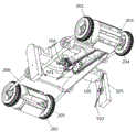
The invention discloses a shrub and lawn dual-purpose garden trimming device, which comprises a machine shell, a push handle, a caster wheel component, a motor, a transmission mechanism and a cutter component, wherein the push handle is arranged on the machine shell; the push handle is arranged on the shell, and the power supply is electrically connected with the motor through a wire; the caster assembly comprises a front caster, a rear caster and a front roller and a rear roller, a front wheel shaft is connected between the front casters, a rear wheel shaft is connected between the rear casters, supporting rods are connected to two sides of the front caster and the rear caster, and the rollers are detachably connected to the front wheel shaft and the rear wheel shaft; the power output end of the motor extends to the lower portion of the machine shell, the transmission mechanism is arranged at the bottom of the machine shell, the motor drives the transmission mechanism, the first cutter is horizontally arranged on the transmission mechanism at the bottom of the machine shell, and the second cutter is vertically arranged at two ends of the transmission mechanism at two sides of the machine shell. The invention adopts two trimming modes of a plane and a side wing, not only can trim the lawn, but also can trim shrubs on both sides of the road, thereby realizing the diversified operation requirement of single equipment.
Description
Technical Field
The invention relates to the technical field of garden equipment, in particular to a bush and lawn dual-purpose garden trimming device.
Background
The garden trimming device is also called a mower, a lawnmower, a weeder and the like, and is a mechanical tool for trimming lawns, vegetation and the like.
However, most of the prior garden trimming devices are four-wheel hand-push type, hand-hold type and stepping type full-automatic lawn mowers. The small tree-shaped green vegetation can only be trimmed manually, especially in recent years, urban afforestation is more and more emphasized, a large number of street tree vegetation appear on two sides of an urban road, a large amount of workload is brought to trimmers, then manual deep trimming cannot be carried out on large shrubs planted in many universities and gardens, a traditional weeding machine cannot assist workers in trimming, and great troubles are brought to garden beautification and urban trimming.
Therefore, it is necessary to develop a garden pruning device for both bush and lawn to solve the above problems.
Disclosure of Invention
The invention aims to provide a shrub and lawn dual-purpose garden trimming device, which adopts two trimming modes of a plane and a side wing, not only can trim a lawn, but also can trim shrubs on two sides of a road, and single equipment can meet different trimming requirements so as to solve the problems in the background technology.
In order to achieve the purpose, the invention provides the following technical scheme:
a shrub and lawn dual-purpose garden trimming device comprises a machine shell, a push handle, a caster wheel component, a motor, a transmission mechanism and a cutter component;
the push handle is arranged on the shell, a groove is formed in the top of the shell, the power supply is detachably arranged in the groove, and the power supply is electrically connected with the motor through a wire;
the caster assembly comprises a group of front casters, a group of rear casters and a front roller and a rear roller, a front wheel shaft is connected between the front casters, a rear wheel shaft is connected between the rear casters, supporting rods are connected to two sides of the front casters and the rear casters, one end of each supporting rod is connected to two ends of the machine shell through an angle adjusting mechanism, and the rollers are detachably connected to the front wheel shaft and the rear wheel shaft;
the motor is arranged on the shell, the power output end of the motor extends to the lower part of the shell, the transmission mechanism is arranged at the bottom of the shell, and the motor drives the transmission mechanism which is connected with the front wheel shaft in a driving way;
the cutter assembly comprises a first cutter and a second cutter, the first cutter is horizontally arranged on a transmission mechanism at the bottom of the machine shell, the second cutter is vertically arranged at two ends of the transmission mechanism at two sides of the machine shell, and grass cutting ropes are arranged at two ends of the first cutter and two ends of the second cutter.
The invention has the further improvement scheme that the top end of the shell is provided with a notch, the motor is fixedly connected with the upper edge of the notch through a transverse plate on the outer side of the motor, an output shaft of the motor is fixedly connected with a first cutter disc, and the first cutter is fixedly connected to the first cutter disc.
The invention has the further improvement scheme that the transmission mechanism comprises a bevel gear A, a transverse shaft and a vertical shaft, the bevel gear A is fixedly connected to an output shaft of the motor, the bottom of the casing is symmetrically and fixedly connected with a support, the transverse shaft is rotatably connected to the support through a bearing sleeve, the two ends of the transverse shaft are fixedly connected with a bevel gear B and a bevel gear C, the two sides of the casing are fixedly connected with U-shaped blocks, through holes are formed in the U-shaped blocks, the transverse shaft penetrates through the U-shaped blocks through the through holes, the bevel gear C is positioned on the outer sides of the U-shaped blocks, and.
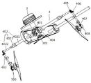
The invention has the further improvement scheme that the vertical shaft is fixedly connected in the cutter holder through a bearing seat, the upper end and the lower end of the vertical shaft are fixedly connected with a bevel gear D and a bevel gear E, the transverse shaft extends into the cutter holder, and the bevel gear C is meshed with the bevel gear D; the cutter holder is characterized in that a cutter shaft is rotatably connected to the inner side wall of the bottom of the cutter holder, a bevel gear F at the rear end of the cutter shaft is meshed with a bevel gear E, a second cutter disc is fixedly connected to the front end of the cutter shaft, and the second cutter is fixedly connected to the second cutter disc.
The invention has the further improvement scheme that a driving chain wheel is fixedly connected to the transverse shaft, a driven chain wheel is fixedly connected to the front wheel shaft, and a chain is in transmission connection between the driving chain wheel and the driven chain wheel.
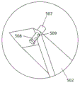
The improved scheme of the invention is that two ends of the first cutter and the second cutter are fixedly connected with thread sleeves, bolts are connected in the thread sleeves, at least one rope hole is formed in each bolt, and a mowing rope penetrates through the rope holes and is locked on the bolts.
The invention has the further improvement scheme that the roller comprises circular plates at two sides, a plurality of amplitude rods are connected between the outer edges of the circular plates, and an obliquely arranged support plate is connected between adjacent amplitude rods; the center of the circular plate is provided with a mounting hole, one side of the mounting hole is provided with a through V-shaped bayonet, the minimum opening size of the V-shaped bayonet is smaller than the inner diameter size of the mounting hole, and the front wheel axle and the rear wheel axle open the V-shaped bayonet and the mounting hole.
The invention has the further improvement scheme that the angle adjusting mechanism comprises a spline disc and a spring, the end part of the supporting rod is fixedly connected with a spline sleeve, half key teeth are arranged in the spline sleeve, and the side without the key teeth in the spline sleeve is rotationally connected with a shell; one end of the spring is fixedly connected to the machine shell, the other end of the spring is fixedly connected to the spline disc, the spline disc is meshed with the spline sleeve, and when the spline disc is pressed down, the spline disc is separated from the spline teeth on the spline disc so as to rotate the supporting rod.
According to a further improvement of the invention, the transverse shaft is of a telescopic structure, and the distance between the two second cutters is changed along with the extension or retraction of the transverse shaft.
The invention has the further improvement scheme that the transverse shaft comprises an inner side section and an outer side section, the end part of the inner side section is fixedly connected with a hexagonal shaft sleeve, the end part of the outer side section is of a hexagonal structure, the outer side section is inserted and locked in the shaft sleeve, and the shaft sleeve is positioned at the opening of the U-shaped block.
The invention has the beneficial effects that:
first, the dual-purpose garden trimming device for shrubs and lawns adopts two trimming modes of a plane and a side wing, not only can be used for trimming lawns, but also can be used for trimming shrubs on two sides of a road, and single equipment can meet different trimming requirements.
Secondly, the shrub and lawn dual-purpose garden trimming device is simple and portable as a whole, scientific and reasonable in structure, low in design and processing cost and convenient to use and maintain.
Thirdly, the second cutter of the dual-purpose garden pruning device for shrubs and lawns is convenient to disassemble, can quickly perform structural transformation of operation in different fields, and is convenient and quick, and high in practicability.
Fourthly, the roller type front and rear supporting wheels of the dual-purpose garden pruning device for the shrubs and the lawns increase the contact area of the vehicle body and the shrubs, so that the vehicle body floats on the shrubs; in addition, the roller is mounted on the front wheel shaft and the rear wheel shaft in a clamping manner, so that the roller is convenient to disassemble and assemble, and the trimming efficiency is improved.
Fifthly, in the dual-purpose garden pruning device for the shrubs and the lawns, the grass cutting ropes are arranged at the two ends of the first cutter and the second cutter, so that the coverage area of the cutters is increased.
Sixth, the angle of the front and rear caster wheels of the dual-purpose garden trimming device for shrubs and lawns is adjustable, and when the lawn is trimmed, the distance between the first cutter and the ground can be adjusted by adjusting the front and rear caster wheels, so that the requirements of lawn trimming at different heights are met; when the shrubs are trimmed, the roller is adjusted upwards, so that the lower opening of the roller is parallel to the first cutter as much as possible.
Seventh, the lateral axis of the garden trimming device for both shrubs and lawns of the invention can be extended and contracted, and the distance between the second cutters can be adjusted according to requirements, so that the requirements of shrub trimming with different width sizes can be met.
Drawings
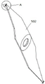
Fig. 1 is a front view of the overall structure of the present invention.
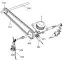
Fig. 2 and 3 are perspective views of the present invention in partial structure.
Fig. 4 and 5 are perspective views of the transmission mechanism of the present invention.
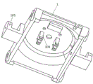
Fig. 6 is a schematic view of the housing structure of the present invention.
FIG. 7 is a schematic view of the structure of the roll of the present invention.
Fig. 8 is a schematic view of a second tool according to the present invention.
Fig. 9 is a partial enlarged view of a portion a in fig. 8.
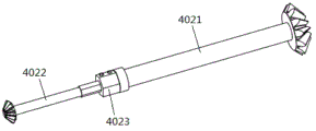
FIG. 10 is a cross-axis schematic of the present invention.
Fig. 11 is a schematic view of an angle adjustment mechanism of the present invention.
In the figure: 1-machine shell, 101-push handle, 102-groove, 103-buckle, 104-support, 105-U-shaped block, 2-caster component, 201-front caster, 202-rear caster, 203-roller, 2031-circular plate, 2032-amplitude bar, 2033-support plate, 2034-bayonet, 2035-mounting hole, 204-front axle, 205-rear axle, 206-support bar, 3-motor, 301-output shaft, 302-horizontal plate, 4-transmission mechanism, 401-bevel gear A, 402-horizontal shaft, 4021-inner section, 4022-outer section, 4023-shaft sleeve, 403-vertical shaft, 404-bevel gear B, 405-bevel gear C, 406-bevel gear D, 407-bevel gear E, 408-bevel gear F, 4023-shaft sleeve, 403-vertical shaft, 404-bevel gear B, 405-bevel gear C, 406-bevel gear D, 407-bevel gear E, 408, 409-a driving sprocket, 410-a driven sprocket, 411-a chain, 5-a cutter assembly, 501-a first cutter, 502-a second cutter, 503-a first cutter disc, 504-a second cutter disc, 505-a cutter holder, 506-a cutter shaft, 507-a thread bush, 508-a bolt, 509-a rope hole, 6-an angle adjusting mechanism, 601-a spline disc, 602-a spring and 603-a spline bush.
Detailed Description
The invention is further elucidated with reference to the drawings and the embodiments.
Example 1: as shown in fig. 1 to 11, a garden pruning device for both shrubs and lawns comprises a housing 1, a push handle 101, a caster component 2, a motor 3, a transmission mechanism 4 and a cutter component 5; the push handle 101 is arranged on the casing 1, the top of the casing 1 is provided with a groove 102, a power supply (not shown in the figure) is detachably arranged in the groove 102 through a buckle 103, and the power supply is electrically connected with the motor 3 through a lead; the caster assembly 2 comprises a group of front casters 201, a group of rear casters 202 and a front roller and a rear roller 203, wherein a front wheel shaft 204 is connected between the front casters 201, a rear wheel shaft 205 is connected between the rear casters 202, supporting rods 206 are connected to two sides of the front casters 201 and the rear casters 202, one end of each supporting rod 206 is connected to two ends of the machine shell 1 through an angle adjusting mechanism 6, and the rollers 203 are detachably connected to the front wheel shaft 204 and the rear wheel shaft 205; the motor 3 is arranged on the machine shell 1, the power output end of the motor 3 extends to the lower part of the machine shell 1, the transmission mechanism 4 is arranged at the bottom of the machine shell 1, the motor 3 drives the transmission mechanism 4, and the transmission mechanism 4 is connected with the front wheel shaft 204 in a driving way; the cutter assembly 5 comprises a first cutter 501 and a second cutter 502, the first cutter 501 is horizontally arranged on the transmission mechanism 4 at the bottom of the machine shell 1, the second cutter 502 is vertically arranged at two ends of the transmission mechanism 4 at two sides of the machine shell 1, and both ends of the first cutter 501 and the second cutter 502 are provided with grass cutting ropes; a notch is formed in the top end of the machine shell 1, the motor 3 is fixedly connected to the upper edge of the notch through a transverse plate 302 on the outer side of the motor 3, a first cutter disc 503 is fixedly connected to an output shaft 301 of the motor 3, and the first cutter 501 is fixedly connected to the first cutter disc 503; the transmission mechanism 4 comprises a bevel gear A401, a transverse shaft 402 and a vertical shaft 403, the bevel gear A401 is fixedly connected to an output shaft 301 of the motor 3, the bottom of the machine shell 1 is symmetrically and fixedly connected with a support 104, the transverse shaft 402 is rotatably connected to the support 104 through a bearing sleeve, two ends of the transverse shaft 402 are fixedly connected with a bevel gear B404 and a bevel gear C405, two sides of the machine shell 1 are fixedly connected with U-shaped blocks 105, through holes are formed in the U-shaped blocks 105, the transverse shaft 402 penetrates through the U-shaped blocks 105 through the through holes, the bevel gear C405 is located on the outer side of the U-shaped blocks 105, and the; the vertical shaft 403 is fixedly connected into the cutter holder 505 through a bearing seat, the upper end and the lower end of the vertical shaft 403 are fixedly connected with a bevel gear D406 and a bevel gear E407, the horizontal shaft 402 extends into the cutter holder 505, and the bevel gear C405 is meshed with the bevel gear D406; a cutter shaft 506 is rotatably connected to the inner side wall of the bottom of the cutter holder 505, a bevel gear F408 at the rear end of the cutter shaft 506 is meshed with a bevel gear E407, a second cutter disc 504 is fixedly connected to the front end of the cutter shaft 506, and a second cutter 502 is fixedly connected to the second cutter disc 504; a driving chain wheel 409 is fixedly connected to the transverse shaft 402, a driven chain wheel 410 is fixedly connected to the front wheel shaft 204, and a chain 411 is connected between the driving chain wheel 409 and the driven chain wheel 410 in a transmission manner; two ends of the first cutter 501 and the second cutter 502 are fixedly connected with threaded sleeves 507, bolts 508 are connected in the threaded sleeves 507, at least one rope hole 509 is formed in each bolt 508, and a mowing rope penetrates through the rope holes 509 and is locked on the bolts 508; the roller 203 comprises circular plates 2031 at two sides, a plurality of amplitude rods 2032 are connected between the outer edges of the circular plates 2031, and a supporting plate 2033 which is obliquely arranged is connected between the adjacent amplitude rods 2032; a mounting hole 2035 is formed in the center of the circular plate 2031, a through V-shaped bayonet 2034 is formed in one side of the mounting hole 2035, the minimum opening size of the V-shaped bayonet 2034 is smaller than the inner diameter size of the mounting hole 2035, and the front axle 204 and the rear axle 205 open the V-shaped bayonet 2034 and the mounting hole 2035; the angle adjusting mechanism 6 comprises a spline disc 601 and a spring 602, the end part of the support rod 206 is fixedly connected with a spline housing 603, half key teeth are arranged in the spline housing 603, and the side without the key teeth in the spline housing 603 is rotationally connected with the machine shell 1; one end of the spring 602 is fixedly connected to the casing 1, the other end of the spring is fixedly connected to the spline disk 601, the spline disk 601 is meshed with the spline housing 603, and when the spline disk 601 is pressed down, the spline disk 601 is separated from the spline teeth on the spline disk 601 to rotate the supporting rod 206.
Example 2: the embodiment is a further improvement of embodiment 1, and the main improvement is that, in the use of embodiment 1, the distance between the second cutters 502 on both sides of the housing 1 cannot be changed, so that the universality is poor when shrubs are trimmed; in the present embodiment, the above-mentioned defects can be avoided, specifically:
the cross shaft 402 is of a telescopic structure, and when the cross shaft 402 extends or retracts, the distance between the two second cutters 502 changes; the transverse shaft 402 comprises an inner section 4021 and an outer section 4022, the end of the inner section 4021 is fixedly connected with a hexagonal shaft sleeve 4023, the end of the outer section 4022 is in a hexagonal structure, the outer section 4022 is inserted and locked in the shaft sleeve 4023, and the shaft sleeve 4023 is positioned at the opening of the U-shaped block 105; when the embodiment is used, the transverse shaft 402 can be stretched, and the distance between the second cutters 502 can be adjusted according to needs, so that the requirements of shrub pruning with different width sizes are met.
Otherwise, this embodiment is identical to embodiment 1, and will not be described herein.
The specific working principle of the invention is as follows:
firstly, when the lawn is trimmed, the lawn is pushed to the lawn, and the height of the first cutter 501 from the ground is adjusted according to the height of the lawn required by the field; during adjustment, the spline disc 601 is pressed down, so that the spline teeth meshed with the spline sleeve 603 on the spline disc 601 are separated, the supporting rod 206 can be rotated, the angle adjustment of the front caster 201 and the rear caster 202 is realized, and the purpose of adjusting the ground clearance of the first cutter 501 is achieved; after the switch is turned on, the motor 3 works, so that the first cutter 501 rotates to realize the trimming of the lawn; in addition, the bevel gear A401 drives the bevel gear B404 to rotate, the transverse shaft 402 rotates along with the bevel gear B404, and the driving chain wheel 409 of the transverse shaft 402 drives the front wheel shaft 204 to rotate, so that the walking of the trimming device is realized.
Before pruning shrubs, the push handle 101 is detached, the tool apron 505 is installed at two ends of the transverse shaft 402, the bevel gear C405 is meshed with the bevel gear D406, the roller 203 is clamped on the front wheel shaft 204 and the rear wheel shaft 205, and the angle of the roller 203 is adjusted in the first step; when the bush is trimmed, the motor 3 works, so that the first cutter 501 rotates to trim the top of the bush; in addition, the bevel gear B404 drives the transverse shaft 402 to rotate, the transverse shaft 402 drives the bevel gear C405 to rotate, the bevel gear C405 drives the vertical shaft 403 to rotate, the vertical shaft 403 drives the cutter shaft 506 to rotate, and therefore the second cutter 502 rotates to trim two sides of a bush; in addition, a driving chain wheel 409 of the transverse shaft 402 drives the front wheel shaft 204 to rotate, and the roller 203 rotates along with the transverse shaft 402, so that the pruning device can walk on the bush.
When the distance between the second cutters 502 needs to be adjusted, the hexagon socket countersunk head screws on the shaft sleeves 4023 are loosened, the outer sections 4022 of the transverse shafts 402 are drawn or inserted, and the hexagon socket countersunk head screws are tightened.
The above embodiments are merely illustrative of the technical concepts and features of the present invention, and the purpose of the embodiments is to enable those skilled in the art to understand the contents of the present invention and implement the present invention, and not to limit the protection scope of the present invention. All equivalent changes and modifications made according to the spirit of the present invention should be covered within the protection scope of the present invention.
Claims (10)
1. The utility model provides a gardens trimming means on bush and lawn dual purpose, its characterized in that: comprises a shell (1), a push handle (101), a caster wheel component (2), a motor (3), a transmission mechanism (4) and a cutter component (5);
the push handle (101) is arranged on the casing (1), a groove (102) is formed in the top of the casing (1), the power supply is detachably arranged in the groove (102) through a buckle (103), and the power supply is electrically connected with the motor (3) through a wire;
the caster wheel assembly (2) comprises a group of front caster wheels (201), a group of rear caster wheels (202) and a front roller and a rear roller (203), wherein a front wheel shaft (204) is connected between the front caster wheels (201), a rear wheel shaft (205) is connected between the rear caster wheels (202), supporting rods (206) are connected to two sides of the front caster wheels (201) and the rear caster wheels (202), one end of each supporting rod (206) is connected to two ends of the machine shell (1) through an angle adjusting mechanism (6), and the rollers (203) are detachably connected to the front wheel shaft (204) and the rear wheel shaft (205);
the motor (3) is arranged on the machine shell (1), the power output end of the motor (3) extends to the lower part of the machine shell (1), the transmission mechanism (4) is arranged at the bottom of the machine shell (1), the motor (3) drives the transmission mechanism (4), and the transmission mechanism (4) is connected with the front wheel shaft (204) in a driving mode;
cutter unit (5) include first cutter (501) and second cutter (502), and on drive mechanism (4) of casing (1) bottom were located to first cutter (501) level, drive mechanism (4) both ends of casing (1) both sides were located vertically to second cutter (502), and the both ends of first cutter (501) and second cutter (502) all are equipped with the rope of cutting grass.
2. The garden trimming apparatus for both shrubs and lawns as defined in claim 1, wherein: the top of casing (1) is equipped with the breach, and motor (3) are followed in the last of breach through diaphragm (302) fixed connection in its outside, and first blade disc (503) of fixedly connected with are gone up in output shaft (301) of motor (3), and first cutter (501) fixed connection is on first blade disc (503).
3. A garden trimming device for both shrubs and lawns as defined in claim 2, wherein: drive mechanism (4) include bevel gear A (401), cross axle (402) and vertical axis (403), bevel gear A (401) fixed connection is on output shaft (301) of motor (3), the symmetrical fixedly connected with support (104) in casing (1) bottom, cross axle (402) pass through the bearing housing and rotate to be connected in support (104), and the both ends fixedly connected with bevel gear B (404) and bevel gear C (405) of cross axle (402), both sides fixedly connected with U type piece (105) of casing (1), be equipped with the through-hole on U type piece (105), cross axle (402) pass through U type piece (105) through the through-hole, bevel gear C (405) are located the outside of U type piece (105), bevel gear A (401) mesh in bevel gear B (404).
4. A garden trimming device for both brush and lawn as claimed in claim 3, wherein: the vertical shaft (403) is fixedly connected into the cutter holder (505) through a bearing seat, the upper end and the lower end of the vertical shaft (403) are fixedly connected with a bevel gear D (406) and a bevel gear E (407), the horizontal shaft (402) extends into the cutter holder (505), and the bevel gear C (405) is meshed with the bevel gear D (406); the inner side wall of the bottom of the tool apron (505) is rotatably connected with a tool shaft (506), a bevel gear F (408) at the rear end of the tool shaft (506) is meshed with a bevel gear E (407), the front end of the tool shaft (506) is fixedly connected with a second cutter head (504), and the second cutter (502) is fixedly connected to the second cutter head (504).
5. A garden trimming device for both brush and lawn as claimed in claim 3, wherein: the driving chain wheel (409) is fixedly connected to the transverse shaft (402), the driven chain wheel (410) is fixedly connected to the front wheel shaft (204), and a chain (411) is connected between the driving chain wheel (409) and the driven chain wheel (410) in a transmission mode.
6. A garden trimming device for both brush and lawn as claimed in claim 4, wherein: the two ends of the first cutter (501) and the second cutter (502) are fixedly connected with thread sleeves (507), bolts (508) are connected in the thread sleeves (507), at least one rope hole (509) is formed in each bolt (508), and a mowing rope penetrates through the rope holes (509) and is locked on the bolts (508).
7. The garden trimming apparatus for both shrubs and lawns as defined in claim 1, wherein: the roller (203) comprises circular plates (2031) at two sides, a plurality of amplitude rods (2032) are connected between the outer edges of the circular plates (2031), and a supporting plate (2033) which is obliquely arranged is connected between the adjacent amplitude rods (2032); the center of the circular plate (2031) is provided with a mounting hole (2035), one side of the mounting hole (2035) is provided with a through V-shaped bayonet (2034), the minimum opening size of the V-shaped bayonet (2034) is smaller than the inner diameter size of the mounting hole (2035), and the front wheel axle (204) and the rear wheel axle (205) open the V-shaped bayonet (2034) and the mounting hole (2035).
8. The garden trimming apparatus for both shrubs and lawns as defined in claim 1, wherein: the angle adjusting mechanism (6) comprises a spline disc (601) and a spring (602), the end part of the support rod (206) is fixedly connected with a spline sleeve (603), half key teeth are arranged in the spline sleeve (603), and the side without the key teeth in the spline sleeve (603) is rotatably connected with the machine shell (1); one end of the spring (602) is fixedly connected to the machine shell (1), the other end of the spring is fixedly connected to the spline disc (601), the spline disc (601) is meshed with the spline sleeve (603), and when the spline disc (601) is pressed down, the spline disc (601) is separated from the spline teeth on the spline disc (601) to rotate the support rod (206).
9. A garden trimming device for both brush and lawn as claimed in claim 4, wherein: the transverse shaft (402) is of a telescopic structure, and when the transverse shaft (402) extends or retracts, the distance between the two second cutters (502) changes.
10. A garden trimming apparatus for both shrubs and lawns, as claimed in claim 9, wherein: the transverse shaft (402) comprises an inner section (4021) and an outer section (4022), the end of the inner section (4021) is fixedly connected with a hexagonal shaft sleeve (4023), the end of the outer section (4022) is of a hexagonal structure, the outer section (4022) is inserted and locked in the shaft sleeve (4023), and the shaft sleeve (4023) is positioned at the opening of the U-shaped block (105).
Priority Applications (1)
| Application Number | Priority Date | Filing Date | Title |
|---|---|---|---|
| CN202010668825.6A CN111955143B (en) | 2020-07-13 | 2020-07-13 | Shrub and garden trimming means on lawn dual purpose |
Applications Claiming Priority (1)
| Application Number | Priority Date | Filing Date | Title |
|---|---|---|---|
| CN202010668825.6A CN111955143B (en) | 2020-07-13 | 2020-07-13 | Shrub and garden trimming means on lawn dual purpose |
Publications (2)
| Publication Number | Publication Date |
|---|---|
| CN111955143A true CN111955143A (en) | 2020-11-20 |
| CN111955143B CN111955143B (en) | 2022-03-18 |
Family
ID=73361809
Family Applications (1)
| Application Number | Title | Priority Date | Filing Date |
|---|---|---|---|
| CN202010668825.6A Active CN111955143B (en) | 2020-07-13 | 2020-07-13 | Shrub and garden trimming means on lawn dual purpose |
Country Status (1)
| Country | Link |
|---|---|
| CN (1) | CN111955143B (en) |
Citations (7)
| Publication number | Priority date | Publication date | Assignee | Title |
|---|---|---|---|---|
| US3811232A (en) * | 1972-07-10 | 1974-05-21 | Massey Ferguson Inc | Knife edge grinder for rotary reel type cutter head |
| CN106576955A (en) * | 2016-11-30 | 2017-04-26 | 常州市双强机械制造有限公司 | Vehicle three-surface hedge trimmer |
| CN108040584A (en) * | 2017-12-25 | 2018-05-18 | 东风农业装备(襄阳)有限公司 | Adjustable clipping device |
| CN108307772A (en) * | 2018-03-29 | 2018-07-24 | 苏州钜昇机电设备工程有限公司 | A kind of double-pole weeder |
| CN108307773A (en) * | 2018-03-29 | 2018-07-24 | 苏州钜昇机电设备工程有限公司 | A kind of weeds cleaning equipment |
| CN108432445A (en) * | 2018-03-29 | 2018-08-24 | 苏州钜昇机电设备工程有限公司 | A kind of weeder |
| CN110679275A (en) * | 2019-10-31 | 2020-01-14 | 杭州易岚永道景观设计有限公司 | Handheld mower |
-
2020
- 2020-07-13 CN CN202010668825.6A patent/CN111955143B/en active Active
Patent Citations (7)
| Publication number | Priority date | Publication date | Assignee | Title |
|---|---|---|---|---|
| US3811232A (en) * | 1972-07-10 | 1974-05-21 | Massey Ferguson Inc | Knife edge grinder for rotary reel type cutter head |
| CN106576955A (en) * | 2016-11-30 | 2017-04-26 | 常州市双强机械制造有限公司 | Vehicle three-surface hedge trimmer |
| CN108040584A (en) * | 2017-12-25 | 2018-05-18 | 东风农业装备(襄阳)有限公司 | Adjustable clipping device |
| CN108307772A (en) * | 2018-03-29 | 2018-07-24 | 苏州钜昇机电设备工程有限公司 | A kind of double-pole weeder |
| CN108307773A (en) * | 2018-03-29 | 2018-07-24 | 苏州钜昇机电设备工程有限公司 | A kind of weeds cleaning equipment |
| CN108432445A (en) * | 2018-03-29 | 2018-08-24 | 苏州钜昇机电设备工程有限公司 | A kind of weeder |
| CN110679275A (en) * | 2019-10-31 | 2020-01-14 | 杭州易岚永道景观设计有限公司 | Handheld mower |
Also Published As
| Publication number | Publication date |
|---|---|
| CN111955143B (en) | 2022-03-18 |
Similar Documents
| Publication | Publication Date | Title |
|---|---|---|
| CN108401644A (en) | A kind of gardens daily maintenance lawn mower | |
| US2913058A (en) | Lawn edger | |
| CN111955143B (en) | Shrub and garden trimming means on lawn dual purpose | |
| CN211322075U (en) | Grass cutting device for landscaping | |
| US2941347A (en) | Mowing implement | |
| CN211482002U (en) | Agricultural is with quick weeding device | |
| CN218125529U (en) | Crop weeding machine | |
| US3693333A (en) | Lawn mower vertical cutter attachment | |
| CN214902011U (en) | Vegetable planting is with device of ploughing | |
| CN212728058U (en) | Hand-push type mower | |
| CN211152816U (en) | Zero turning radius lawn mower of integrative formula of increaseing | |
| CN208359916U (en) | A kind of walking mechanism of grass-removing robot | |
| CN211630860U (en) | Heavy bush-cutting mower | |
| CN111758413A (en) | Bush ball trimming means for afforestation | |
| CN111567212A (en) | Novel multifunctional remote control mowing and pesticide applying machine | |
| CN116491294B (en) | Garden weeder capable of collecting weeds | |
| CN212393253U (en) | Gardens are planted and are used weeding device | |
| CN219459828U (en) | Hedge trimming trimmer | |
| CN219834885U (en) | Intelligent grass mower | |
| CN215301563U (en) | Lawn repair system for garden landscape | |
| CN215935594U (en) | Conveniently collect ruderal gardens weed harvester | |
| CN210900248U (en) | Dry land rural weeding device | |
| CN218473780U (en) | Garden mower with double cutting tool bits | |
| CN215454016U (en) | Adjustable auxiliary roller device and lawn mower thereof | |
| CN210076077U (en) | Tall and big tree trimming means in gardens |
Legal Events
| Date | Code | Title | Description |
|---|---|---|---|
| PB01 | Publication | ||
| PB01 | Publication | ||
| SE01 | Entry into force of request for substantive examination | ||
| SE01 | Entry into force of request for substantive examination | ||
| GR01 | Patent grant | ||
| GR01 | Patent grant | ||
| EE01 | Entry into force of recordation of patent licensing contract |
Application publication date: 20201120 Assignee: Shenzhen Zhonghuineng Technology Co.,Ltd. Assignor: HUAIYIN INSTITUTE OF TECHNOLOGY Contract record no.: X2023320000252 Denomination of invention: A dual-purpose garden pruning device for shrubs and lawns Granted publication date: 20220318 License type: Common License Record date: 20231211 |
|
| EE01 | Entry into force of recordation of patent licensing contract |