CN111936091B - Ophthalmic microsurgical instrument - Google Patents
Ophthalmic microsurgical instrument Download PDFInfo
- Publication number
- CN111936091B CN111936091B CN201880075174.0A CN201880075174A CN111936091B CN 111936091 B CN111936091 B CN 111936091B CN 201880075174 A CN201880075174 A CN 201880075174A CN 111936091 B CN111936091 B CN 111936091B
- Authority
- CN
- China
- Prior art keywords
- trocar
- composite microcannula
- microcannula
- distal end
- microsurgical instrument
- Prior art date
- Legal status (The legal status is an assumption and is not a legal conclusion. Google has not performed a legal analysis and makes no representation as to the accuracy of the status listed.)
- Active
Links
- 239000002131 composite material Substances 0.000 claims abstract description 196
- 230000035515 penetration Effects 0.000 claims abstract description 15
- 239000012530 fluid Substances 0.000 claims description 41
- 238000006073 displacement reaction Methods 0.000 claims description 16
- 239000000463 material Substances 0.000 claims description 15
- 239000011800 void material Substances 0.000 claims description 15
- 230000007704 transition Effects 0.000 claims description 14
- 239000007787 solid Substances 0.000 claims description 12
- 238000004891 communication Methods 0.000 claims description 4
- 238000000034 method Methods 0.000 abstract description 10
- 210000001519 tissue Anatomy 0.000 description 41
- 210000003786 sclera Anatomy 0.000 description 30
- 239000003550 marker Substances 0.000 description 19
- 238000001356 surgical procedure Methods 0.000 description 9
- 229940079593 drug Drugs 0.000 description 7
- 239000003814 drug Substances 0.000 description 7
- 238000003780 insertion Methods 0.000 description 7
- 230000037431 insertion Effects 0.000 description 7
- 210000001585 trabecular meshwork Anatomy 0.000 description 7
- 230000000007 visual effect Effects 0.000 description 7
- 210000001742 aqueous humor Anatomy 0.000 description 6
- 239000011248 coating agent Substances 0.000 description 6
- 238000000576 coating method Methods 0.000 description 6
- 238000010586 diagram Methods 0.000 description 6
- 230000007246 mechanism Effects 0.000 description 6
- 210000001747 pupil Anatomy 0.000 description 6
- 239000007788 liquid Substances 0.000 description 5
- 210000003462 vein Anatomy 0.000 description 5
- 238000005520 cutting process Methods 0.000 description 4
- 239000010410 layer Substances 0.000 description 4
- 230000003287 optical effect Effects 0.000 description 3
- 239000013307 optical fiber Substances 0.000 description 3
- 230000037361 pathway Effects 0.000 description 3
- 238000011176 pooling Methods 0.000 description 3
- 238000000926 separation method Methods 0.000 description 3
- 238000011282 treatment Methods 0.000 description 3
- 208000010412 Glaucoma Diseases 0.000 description 2
- 208000035965 Postoperative Complications Diseases 0.000 description 2
- 230000005670 electromagnetic radiation Effects 0.000 description 2
- 208000015181 infectious disease Diseases 0.000 description 2
- 230000001678 irradiating effect Effects 0.000 description 2
- 238000012544 monitoring process Methods 0.000 description 2
- 230000000149 penetrating effect Effects 0.000 description 2
- 230000003068 static effect Effects 0.000 description 2
- 238000012546 transfer Methods 0.000 description 2
- 239000003190 viscoelastic substance Substances 0.000 description 2
- 201000004569 Blindness Diseases 0.000 description 1
- 241001149900 Fusconaia subrotunda Species 0.000 description 1
- 208000022873 Ocular disease Diseases 0.000 description 1
- 208000031481 Pathologic Constriction Diseases 0.000 description 1
- FAPWRFPIFSIZLT-UHFFFAOYSA-M Sodium chloride Chemical compound [Na+].[Cl-] FAPWRFPIFSIZLT-UHFFFAOYSA-M 0.000 description 1
- 239000002390 adhesive tape Substances 0.000 description 1
- 210000002159 anterior chamber Anatomy 0.000 description 1
- 238000005452 bending Methods 0.000 description 1
- 230000009286 beneficial effect Effects 0.000 description 1
- 230000008901 benefit Effects 0.000 description 1
- 210000004204 blood vessel Anatomy 0.000 description 1
- 230000008859 change Effects 0.000 description 1
- 238000005234 chemical deposition Methods 0.000 description 1
- 239000003795 chemical substances by application Substances 0.000 description 1
- 210000004087 cornea Anatomy 0.000 description 1
- 230000008878 coupling Effects 0.000 description 1
- 238000010168 coupling process Methods 0.000 description 1
- 238000005859 coupling reaction Methods 0.000 description 1
- 238000000151 deposition Methods 0.000 description 1
- 230000008021 deposition Effects 0.000 description 1
- 230000004406 elevated intraocular pressure Effects 0.000 description 1
- 208000030533 eye disease Diseases 0.000 description 1
- 238000001415 gene therapy Methods 0.000 description 1
- 238000005286 illumination Methods 0.000 description 1
- 238000002347 injection Methods 0.000 description 1
- 239000007924 injection Substances 0.000 description 1
- 208000014674 injury Diseases 0.000 description 1
- 230000002452 interceptive effect Effects 0.000 description 1
- 230000004410 intraocular pressure Effects 0.000 description 1
- 238000002483 medication Methods 0.000 description 1
- 238000000465 moulding Methods 0.000 description 1
- 239000002105 nanoparticle Substances 0.000 description 1
- -1 objects Substances 0.000 description 1
- 210000000056 organ Anatomy 0.000 description 1
- 239000002245 particle Substances 0.000 description 1
- 238000002360 preparation method Methods 0.000 description 1
- 238000003825 pressing Methods 0.000 description 1
- 230000008569 process Effects 0.000 description 1
- 231100000241 scar Toxicity 0.000 description 1
- 230000037390 scarring Effects 0.000 description 1
- 239000002356 single layer Substances 0.000 description 1
- 239000011780 sodium chloride Substances 0.000 description 1
- 239000000243 solution Substances 0.000 description 1
- 210000000130 stem cell Anatomy 0.000 description 1
- 230000036262 stenosis Effects 0.000 description 1
- 208000037804 stenosis Diseases 0.000 description 1
- 238000002560 therapeutic procedure Methods 0.000 description 1
- 230000009772 tissue formation Effects 0.000 description 1
- 230000008733 trauma Effects 0.000 description 1
- 229940006076 viscoelastic substance Drugs 0.000 description 1
- 230000004393 visual impairment Effects 0.000 description 1
- XLYOFNOQVPJJNP-UHFFFAOYSA-N water Substances O XLYOFNOQVPJJNP-UHFFFAOYSA-N 0.000 description 1
Images


Classifications
-
- A—HUMAN NECESSITIES
- A61—MEDICAL OR VETERINARY SCIENCE; HYGIENE
- A61F—FILTERS IMPLANTABLE INTO BLOOD VESSELS; PROSTHESES; DEVICES PROVIDING PATENCY TO, OR PREVENTING COLLAPSING OF, TUBULAR STRUCTURES OF THE BODY, e.g. STENTS; ORTHOPAEDIC, NURSING OR CONTRACEPTIVE DEVICES; FOMENTATION; TREATMENT OR PROTECTION OF EYES OR EARS; BANDAGES, DRESSINGS OR ABSORBENT PADS; FIRST-AID KITS
- A61F9/00—Methods or devices for treatment of the eyes; Devices for putting-in contact lenses; Devices to correct squinting; Apparatus to guide the blind; Protective devices for the eyes, carried on the body or in the hand
- A61F9/007—Methods or devices for eye surgery
- A61F9/00781—Apparatus for modifying intraocular pressure, e.g. for glaucoma treatment
-
- A—HUMAN NECESSITIES
- A61—MEDICAL OR VETERINARY SCIENCE; HYGIENE
- A61B—DIAGNOSIS; SURGERY; IDENTIFICATION
- A61B17/00—Surgical instruments, devices or methods, e.g. tourniquets
- A61B17/34—Trocars; Puncturing needles
- A61B17/3415—Trocars; Puncturing needles for introducing tubes or catheters, e.g. gastrostomy tubes, drain catheters
-
- A—HUMAN NECESSITIES
- A61—MEDICAL OR VETERINARY SCIENCE; HYGIENE
- A61B—DIAGNOSIS; SURGERY; IDENTIFICATION
- A61B90/00—Instruments, implements or accessories specially adapted for surgery or diagnosis and not covered by any of the groups A61B1/00 - A61B50/00, e.g. for luxation treatment or for protecting wound edges
- A61B90/30—Devices for illuminating a surgical field, the devices having an interrelation with other surgical devices or with a surgical procedure
-
- A—HUMAN NECESSITIES
- A61—MEDICAL OR VETERINARY SCIENCE; HYGIENE
- A61F—FILTERS IMPLANTABLE INTO BLOOD VESSELS; PROSTHESES; DEVICES PROVIDING PATENCY TO, OR PREVENTING COLLAPSING OF, TUBULAR STRUCTURES OF THE BODY, e.g. STENTS; ORTHOPAEDIC, NURSING OR CONTRACEPTIVE DEVICES; FOMENTATION; TREATMENT OR PROTECTION OF EYES OR EARS; BANDAGES, DRESSINGS OR ABSORBENT PADS; FIRST-AID KITS
- A61F9/00—Methods or devices for treatment of the eyes; Devices for putting-in contact lenses; Devices to correct squinting; Apparatus to guide the blind; Protective devices for the eyes, carried on the body or in the hand
- A61F9/0008—Introducing ophthalmic products into the ocular cavity or retaining products therein
- A61F9/0017—Introducing ophthalmic products into the ocular cavity or retaining products therein implantable in, or in contact with, the eye, e.g. ocular inserts
-
- A—HUMAN NECESSITIES
- A61—MEDICAL OR VETERINARY SCIENCE; HYGIENE
- A61F—FILTERS IMPLANTABLE INTO BLOOD VESSELS; PROSTHESES; DEVICES PROVIDING PATENCY TO, OR PREVENTING COLLAPSING OF, TUBULAR STRUCTURES OF THE BODY, e.g. STENTS; ORTHOPAEDIC, NURSING OR CONTRACEPTIVE DEVICES; FOMENTATION; TREATMENT OR PROTECTION OF EYES OR EARS; BANDAGES, DRESSINGS OR ABSORBENT PADS; FIRST-AID KITS
- A61F9/00—Methods or devices for treatment of the eyes; Devices for putting-in contact lenses; Devices to correct squinting; Apparatus to guide the blind; Protective devices for the eyes, carried on the body or in the hand
- A61F9/007—Methods or devices for eye surgery
- A61F9/00709—Instruments for removing foreign bodies
-
- A—HUMAN NECESSITIES
- A61—MEDICAL OR VETERINARY SCIENCE; HYGIENE
- A61F—FILTERS IMPLANTABLE INTO BLOOD VESSELS; PROSTHESES; DEVICES PROVIDING PATENCY TO, OR PREVENTING COLLAPSING OF, TUBULAR STRUCTURES OF THE BODY, e.g. STENTS; ORTHOPAEDIC, NURSING OR CONTRACEPTIVE DEVICES; FOMENTATION; TREATMENT OR PROTECTION OF EYES OR EARS; BANDAGES, DRESSINGS OR ABSORBENT PADS; FIRST-AID KITS
- A61F9/00—Methods or devices for treatment of the eyes; Devices for putting-in contact lenses; Devices to correct squinting; Apparatus to guide the blind; Protective devices for the eyes, carried on the body or in the hand
- A61F9/007—Methods or devices for eye surgery
- A61F9/00736—Instruments for removal of intra-ocular material or intra-ocular injection, e.g. cataract instruments
-
- A—HUMAN NECESSITIES
- A61—MEDICAL OR VETERINARY SCIENCE; HYGIENE
- A61B—DIAGNOSIS; SURGERY; IDENTIFICATION
- A61B17/00—Surgical instruments, devices or methods, e.g. tourniquets
- A61B17/34—Trocars; Puncturing needles
- A61B17/3417—Details of tips or shafts, e.g. grooves, expandable, bendable; Multiple coaxial sliding cannulas, e.g. for dilating
- A61B17/3421—Cannulas
-
- A—HUMAN NECESSITIES
- A61—MEDICAL OR VETERINARY SCIENCE; HYGIENE
- A61B—DIAGNOSIS; SURGERY; IDENTIFICATION
- A61B90/00—Instruments, implements or accessories specially adapted for surgery or diagnosis and not covered by any of the groups A61B1/00 - A61B50/00, e.g. for luxation treatment or for protecting wound edges
- A61B90/30—Devices for illuminating a surgical field, the devices having an interrelation with other surgical devices or with a surgical procedure
- A61B2090/306—Devices for illuminating a surgical field, the devices having an interrelation with other surgical devices or with a surgical procedure using optical fibres
-
- A—HUMAN NECESSITIES
- A61—MEDICAL OR VETERINARY SCIENCE; HYGIENE
- A61B—DIAGNOSIS; SURGERY; IDENTIFICATION
- A61B90/00—Instruments, implements or accessories specially adapted for surgery or diagnosis and not covered by any of the groups A61B1/00 - A61B50/00, e.g. for luxation treatment or for protecting wound edges
- A61B90/36—Image-producing devices or illumination devices not otherwise provided for
- A61B90/361—Image-producing devices, e.g. surgical cameras
- A61B2090/3612—Image-producing devices, e.g. surgical cameras with images taken automatically
-
- A—HUMAN NECESSITIES
- A61—MEDICAL OR VETERINARY SCIENCE; HYGIENE
- A61B—DIAGNOSIS; SURGERY; IDENTIFICATION
- A61B90/00—Instruments, implements or accessories specially adapted for surgery or diagnosis and not covered by any of the groups A61B1/00 - A61B50/00, e.g. for luxation treatment or for protecting wound edges
- A61B90/39—Markers, e.g. radio-opaque or breast lesions markers
- A61B2090/3937—Visible markers
- A61B2090/3945—Active visible markers, e.g. light emitting diodes
-
- A—HUMAN NECESSITIES
- A61—MEDICAL OR VETERINARY SCIENCE; HYGIENE
- A61B—DIAGNOSIS; SURGERY; IDENTIFICATION
- A61B3/00—Apparatus for testing the eyes; Instruments for examining the eyes
- A61B3/0008—Apparatus for testing the eyes; Instruments for examining the eyes provided with illuminating means
Abstract
In some embodiments, a microsurgical instrument includes a trocar having a hollow rigid shaft formed with a lumen extending from a proximal end to a distal end of the shaft. The distal end of the shaft may be shaped for tissue penetration. The instrument may further include a composite microcannula slidably engaged with the trocar within the lumen. The microcannula includes a light guide and a flexible hollow tube having an outer diameter that is smaller than an inner diameter of a lumen in the trocar. Other embodiments include: the method includes placing the microcannula in a lumen of the trocar, illuminating an end of the trocar by illuminating the end of the microcannula, advancing the trocar from a selected entry point on the eye into a selected structure in the eye, and extending the illuminated end of the microcannula from the trocar into the selected structure.
Description
Cross Reference to Related Applications
This application is a continuation of the application in part of co-pending application serial No. 15/892,833, filed on day 2, 2018, which is incorporated herein by reference in its entirety, which claims the benefit of U.S. provisional patent application No. 62/574,136 filed on day 10, 2017, 18, which is incorporated herein by reference in its entirety.
Technical Field
Embodiments relate to surgical devices for treating eye disorders such as glaucoma.
Background
Aqueous humor is a transparent aqueous fluid that is produced within the eye, fills the anterior and posterior chambers of the eye, delivers the agents required for ocular tissue, and helps maintain the rounded shape of the eye by fluid pressure. Aqueous humor flows out of the eye through a fluid drainage network that includes trabecular meshwork and schlemm's canal, porous circumferential fluid channels connected to collector channels, and veins. Obstruction or collapse of portions of the eye's drainage network may lead to elevated intraocular pressure, which may be associated with ocular diseases such as vision loss and glaucoma.
Surgical treatments may be used to reduce intraocular pressure by improving aqueous humor flow. Some surgical treatments involve making a relatively large incision through the sclera, the white rigid outer covering of the eye, thereby forming a tissue flap that is folded back to expose the trabecular meshwork or other portions of the aqueous humor pathway. The exposed portion of the drainage network may then be modified by removing tissue or creating a new drainage channel. Incisions through the sclera may result in loss of fluid pressure within the eye and collapse of one or more of the houses. It may be necessary to support the natural shape of the eye by injecting a viscoelastic fluid into one of the chambers. The viscoelastic fluid has a viscosity that changes from a dynamic flow state to a static flow state, flows at a relatively low viscosity when subjected to shear stress, and assumes a gelatinous high viscosity state under static conditions.
Surgical treatment involving eye incisions may increase the risk of postoperative complications such as infection and scar tissue formation. Other therapeutic procedures have been developed that are less damaging to the eye. For example, the flow of aqueous humor may be improved by passing a microcannula through portions of the eye's drainage network to remove obstructions or reopen collapsed fluid pathways. In addition, it may be advantageous to deliver drugs or drug eluting devices or materials into tissue structures. Notably, since schlemm is located outside of the immunocompetent region within the body of the human eye, it may be beneficial to deliver drugs and drug eluting devices to schlemm. The microcannula may comprise a flexible hollow tube having an outer diameter small enough to permit introduction of the microcannula into schlemm's canal or some other portion of the eye's drainage network. The microcannula may be flexible enough to follow the schlemm's canal or another portion of the drainage network as the microcannula is pushed from outside the eye (e.g., through a surgically formed flap as previously described or through a penetration of the sclera). The microcannula may be used to mechanically dilate selected portions of the drainage channel in the eye, or may be used to infuse materials, objects, fluids, medications, or viscoelastic substances to apply fluid pressure to improve flow through the ocular drainage system. Alternatively, a microsurgical cutting, penetrating or grasping instrument may be passed through the microcannula to direct the instrument to the site of the eye to be surgically modified.
Some microsurgical instruments have a microcannula slidably engaged with a hollow flexible outer sheath. The flexible outer sheath may be used to position the entry point of the microcannula into the interior of the eye, wherein the microcannula passes through a lumen in the flexible outer sheath and the outer sheath remains stationary relative to the eye. The end of the microcannula may extend from the end of the sheath into a selected portion of the eye. However, the flexibility of the outer sheath may make it difficult for the sheath to penetrate the sclera or other tissue, thereby preventing the microcannula from accessing drainage structures or other treatment areas within the eye. It may be necessary to make an incision or puncture with a separate instrument to permit accurate positioning of the flexible sheath for placement and guidance of the microcannula. Alternatively, the microcannula may be provided with a tip shaped for tissue penetration, which may limit the use of the microcannula for delivering a payload into the interior of the eye.
Disclosure of Invention
One exemplary device embodiment includes a trocar and a composite microcannula. Embodiments of a trocar include a rigid shaft having a proximal end and a distal end. The rigid shaft may be formed with a lumen extending from the proximal end to the distal end. The distal end of the rigid shaft on the trocar may be shaped for tissue penetration.
A composite microcannula may be positioned within the lumen of the trocar. An example of the composite microcannula may include a flexible hollow tube having an outer diameter that is less than an inner diameter of the lumen of the trocar. An example of the composite microcannula may further include a light guide.
Another exemplary device embodiment includes a trocar for ophthalmic surgery. Examples of trocars include a hollow rigid shaft having a distal end shaped for tissue penetration. The hollow shaft is formed with a lumen extending from a distal end of the hollow shaft to a proximal end of the hollow shaft. The example trocar further includes a transition structure attached to the proximal end of the hollow shaft. The transition structure may be formed with a hole for allowing the composite microcannula to enter the lumen. An example of the trocar may further include a light source arranged to illuminate the distal end of the hollow rigid shaft. The distal edge of the lumen in the hollow shaft may be smoothed to reduce wear and/or cutting caused by solids passing through the lumen and exiting the trocar. An example of the trocar may further include a finger grip extending outwardly from the transition structure.
An exemplary method embodiment includes: placing the distal end of the composite microcannula within the lumen of the trocar; illuminating the distal end of the composite microcannula, thereby illuminating the distal end of the trocar; selecting a trocar access point on the eye and positioning the trocar at the selected access point; advancing the trocar at the selected entry point until the illuminated distal end of the trocar is observed to enter a selected structure in the eye; and extending the composite microcannula from the distal end of the trocar toward a target area in the eye, thereby transitioning from illuminating the distal end of the trocar to illuminating tissue outside of the trocar.
Another exemplary device includes: a hand piece; an actuator slidably coupled to the handpiece; an insert slidably coupled to the handpiece; a hollow tube attached to the actuator; and a wire passing through the hollow tube, a first end of the wire being attached to the handpiece and a second end of the wire being attached to the insert.
Another exemplary trocar for ophthalmic surgery includes, inter alia, a hollow rigid shaft including a lumen for receiving a cannula, particularly a composite microcannula, wherein the shaft has a distal end shaped for tissue penetration.
The distal end of the shaft may be beveled or tapered. Alternatively or additionally, the distal end of the shaft is formed such that tissue penetration results in a single penetration of the tissue.
The inner surface of the distal end of the shaft may be smoother than at least a portion of the inner surface of the remainder of the shaft. Further, the distal edge of the shaft may be smoother than at least a portion of the inner surface of the remainder of the shaft. The outer surface of the shaft may include a lubricious coating.
The trocar may include a light guide and/or a light source arranged such that the distal end of the shaft may be illuminated. In particular, one end of the light guide may be used to illuminate the distal end of the shaft and/or tissue. The cross-section of this end of the light guide may be larger than the cross-section of at least a part of the rest of the light guide and/or the other end of the light guide may be connected with a light source for providing visible and invisible light.
The light guide may be attached to the shaft or may be an integral part of the shaft.
Another exemplary device may include the trocar and cannula described above. The cannula may be a composite microcannula and/or may be disposed within the lumen of the trocar.
The cannula may have a stiffness less than the stiffness of the shaft. The cannula may have a diameter in the range from 100 microns to 250 microns.
The cannula may include a lumen extending between the two ends of the cannula. Through the cannula, and in particular the lumen of the cannula, the payload may be allowed to enter the tissue as the cannula protrudes from the distal end of the hollow shaft, and/or through the cannula, the payload may be allowed to enter the tissue, wherein the shaft remains in the same position during the allowing of the payload into the tissue.
The device may comprise a switching structure, in particular a trocar connector. The trocar, and in particular the proximal end of the shaft, may be connected to the transition structure. In addition, the cannula may extend through the switching structure.
The light guide or another light guide may be coupled to the cannula. In particular, the light guide or another light guide may be attached to the cannula or may be an integral part of the cannula. Alternatively, the light guide may be arranged such that the end of the shaft may be illuminated irrespective of the presence or position of the cannula.
The light guide and/or the further light guide may be connected to the light source. The device may comprise a mirror arranged to direct light from said light source to said proximal end of said shaft.
The lumen of the cannula may be fluidly connected to an injector of a material, in particular a viscoelastic material.
Drawings
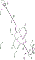
FIG. 1 is a diagram of an exemplary embodiment of a microsurgical instrument including a trocar having a hollow rigid shaft, and a flexible composite microcannula.
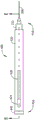
Fig. 2 is a top view of an example of a trocar according to an embodiment.
Fig. 3 is a side view of an example of the trocar of fig. 2.
Fig. 4 is a cross-sectional view A-A of an example of the trocar of fig. 1-3. The cross-sectional line labeled A-A in fig. 3 shows the position and viewing direction of the cross-sectional view of fig. 4.
Fig. 5 is an enlarged partial cross-sectional view B of the hollow rigid shaft of fig. 1-4, showing an example of a distal end shaped for tissue penetration, and further showing an example of a smoothed distal edge of a lumen in a trocar. The position of view B in fig. 5 is marked with a dashed line in fig. 4.
Fig. 6 is a partial top view of an example of a composite microcannula according to an embodiment of a microsurgical instrument.
Fig. 7 is a cross-sectional view C-C of the exemplary composite microcannula of fig. 6. The position and viewing direction of the cross-sectional view C-C in fig. 7 is marked with a longitudinal cross-sectional line C-C in fig. 6.
Fig. 8 is a cross-sectional view D-D of the exemplary composite microcannula of fig. 6. The position and viewing direction of the cross-sectional view D-D in fig. 8 is marked with a transverse cross-sectional line D-D in fig. 6.
Fig. 9 is an alternative cross-sectional view D-D of another example of a composite microcannula in accordance with an embodiment of the microsurgical instrument. The location and viewing direction of the alternative cross-sectional view D-D in fig. 9 is marked with a transverse cross-sectional line D-D in fig. 6.
Fig. 10 is an alternative cross-sectional view D-D of another example of a composite microcannula in accordance with an embodiment of the microsurgical instrument. The location and viewing direction of the alternative cross-sectional view D-D in fig. 10 is marked with a transverse cross-sectional line D-D in fig. 6.
Fig. 11 is an alternative cross-sectional view D-D of another example of a composite microcannula in accordance with an embodiment of the microsurgical instrument. The location and viewing direction of the alternative cross-sectional view D-D in fig. 11 is marked with a transverse cross-sectional line D-D in fig. 6.
Fig. 12 is an alternative cross-sectional view A-A of another example of a trocar, further illustrating an example of a composite microcannula offset from the distal end of the trocar in a proximal direction, and further illustrating an example of an illuminated distal end of the trocar.
Fig. 13 is a continuation of the example of fig. 12, showing an example where the illuminated distal end of the composite microcannula extends outwardly from the distal end of the lumen in the trocar.
Fig. 14 is an alternative cross-sectional view D-D showing another example of a composite microcannula having two light guides in the interior longitudinal void of a flexible hollow tube of the composite microcannula.
Fig. 15 is an alternative cross-sectional view D-D showing another example of a composite microcannula having two light guides, one light guide being located inside the flexible hollow tube of the composite microcannula and the other light guide being in contact with the outer surface of the flexible hollow tube.
Fig. 16 is an alternative cross-sectional view D-D showing another example of a composite microcannula having two light guides, one light guide located in the interior of a flexible hollow tube of the composite microcannula and the other light guide located between the hollow tube and the outer cannula.
Fig. 17 is an alternative cross-sectional view D-D showing another example of a composite microcannula having two light guides, one light guide being located inside a flexible hollow tube of the composite microcannula and a second light guide being held against the flexible hollow tube by an outer coating applied over the second light guide and the flexible hollow tube.
Fig. 18 is a block diagram of an alternative device embodiment including a positioner for displacing the composite microcannula relative to the trocar and optionally including a fluid injector for introducing fluid into the composite microcannula.
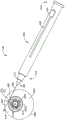
Fig. 19 shows a top view of an example of an embodiment of a microsurgical instrument having a locator and a trocar.
Fig. 20 is a cross-sectional view E-E of an example of the positioner of fig. 19. The location and viewing direction of the sectional view E-E in FIG. 20 is marked with a longitudinal section line labeled E-E in FIG. 19.
Fig. 21 shows a diagram of an exemplary microsurgical instrument embodiment that includes a locator in which the distal tip of the trocar passes through the sclera of the eye into schlemm's canal, illustrating an example in which light emitted from the illuminated distal end of the trocar accurately indicates the position of the trocar.
Fig. 22 shows a view of an exemplary microsurgical instrument and trocar in the same position relative to schlemm's canal as in fig. 21, and further illustrates an example of an illuminated distal tip of a composite microcannula extending outwardly from the trocar along the circumferential path of schlemm's canal.
Fig. 23 is another alternative cross-sectional view A-A of the example of the trocar of fig. 1, showing an example of a composite microcannula and its light guide passing through the lumen of the trocar, and further showing an optional second light guide positioned in the lumen separate from the light guide in the composite microcannula.
Fig. 24 shows a partial view of a trocar with a composite microcannula and a second light guide as in the example of fig. 23, showing an example in which the illuminated distal ends of the trocar and the composite microcannula are separated from each other along the circumferential path of schlemm's canal.
Fig. 25 shows an alternative cross-sectional view D-D of an example of a composite microcannula embodiment carrying an example of an alternative fluid payload and an example of an alternative solid payload within a flexible hollow tube.
Fig. 26 shows a diagram of an example of a trocar access point marker.
Fig. 27 shows a view of an example of a marking surface on a marking pad of the trocar access point marker of fig. 26.
Fig. 28 illustrates a side view of the exemplary trocar access point marker of fig. 26-27.
Fig. 29 shows a view of an example of the sclera and iris of a human eye, illustrating an example of the pattern of tangents formed by the trocar access point marker of fig. 26-28.
Fig. 30 illustrates an example of some of the steps involved in a method for inserting a trocar through the sclera of an eye and pushing a composite microcannula from the trocar into a structure such as schlemm's canal.
Fig. 31 is a partial top view of another example of a composite microcannula according to an embodiment of the microsurgical instrument.
Fig. 32 is a cross-sectional view F-F of the exemplary composite microcannula of fig. 31. The position and viewing direction of the cross-sectional view F-F in FIG. 32 is marked with the longitudinal cross-sectional line F-F in FIG. 31.
Fig. 33 is a cross-sectional view G-G of the exemplary composite microcannula of fig. 30-31. The position and viewing direction of the cross-sectional view G-G in fig. 33 is marked with the transverse cross-section G-G in fig. 31.
Fig. 34 is a view of the top side of another example of an embodiment of a microsurgical instrument having a locator and a trocar.
Fig. 35 is a side view of two of the microsurgical instrument examples of fig. 34, with the upper device showing an example composite microcannula in a retracted position and the lower device showing an example composite microcannula in an extended position.
Fig. 36 is a continuation of the example of fig. 34-35, showing an example of a cross-sectional view H-H of the microsurgical instrument with the composite microcannula in the retracted position and a cross-sectional view K-K of the composite microcannula in the extended position. The locations of sections H-H and K-K are marked with section lines H-H and K-K in FIG. 35.
Detailed Description
Exemplary embodiments according to the present invention are described herein. A trocar having a hollow rigid shaft with a distal end shaped for tissue penetration is configured to pierce biological tissue (e.g., the sclera of an eye) to form a very small entry point into the tissue for a composite microcannula to pass through the lumen of the trocar. The composite microcannula (also referred to herein as a microcatheter) includes a light guide for illuminating the distal end of the microcannula. A light source may be coupled to the composite microcannula and/or the trocar to illuminate the distal end of the hollow rigid shaft by directing light through the light guide into the lumen of the trocar, thereby enabling accurate determination of the position of the distal end of the trocar, a visual indication of the entry of the trocar into the ocular structure, and a visual indication of the position of the distal end of the composite microcannula as it travels toward the target treatment area. The illuminated distal end of the composite microcannula may be used to determine when the microcannula is deviated from the preferred path, e.g., out of the preferred path through schlemm's canal and into another channel or room, such as a collector channel or another portion of the ocular drainage system.
By observing the light emitted from the trocar through tissue (which may include sclera, trabecular meshwork, or other tissue, including tissue not associated with the eye), the embodiments effectively provide a visual indication of the location of the distal end of the trocar. Light passing from the trocar through the sclera or other tissue further indicates the direction of travel of the trocar. The position and direction of travel of the composite microcannula may also be accurately determined by visual observation of the light emanating from the tip of the microcannula. Embodiments may be accurately directed into tissue and/or tissue space such as, but not limited to, trabecular meshwork, schlemm's canal, and collector channels. Rather, embodiments may be directed accurately to specifically avoid access to selected tissues or tissue gaps. The tissue in the eye, as well as the position and direction of travel of the embodiment, may be directly observed using a camera, using a gonioscopic mirror (gonioprism), using other optical aids, or any combination of these devices and methods.
In some embodiments, the second light guide enables independent and optionally simultaneous illumination of the distal ends of the trocar and the composite microcannula. In other embodiments, payloads including fluids and/or solids may be delivered through a composite microcannula to a target area in the eye. Examples of fluid payloads include, but are not limited to: including gene therapy, stem cells and other fluid-based drugs, viscoelastic fluids, water, and saline solutions. Examples of solid payloads include, but are not limited to: devices, particles, nanoparticles, small devices including drug eluting examples of solid payloads, microsurgical instruments such as forceps, instruments for penetrating and/or cutting tissue, stents, light guides, and wires. As used herein, a light guide refers to an optical element capable of transmitting electromagnetic energy received at an input surface to an output surface through an intermediate optical medium. Examples of light guides include, but are not limited to: one or more mirrors, a flexible optical fiber, a bundle of optical fibers, and a rigid light pipe arranged to direct a light beam from a source to an end point.
Some embodiments include a positioner for displacing the composite microcannula relative to the distal end of the trocar. The positioner may optionally include a microcannula displacement mechanism configured to extend and optionally retract the composite microcannula. The locator may further optionally include a fluid injector configured to move fluid from the fluid reservoir into the composite microcannula and into a selected target area in the eye. Some embodiments of the locator include a light source arranged to emit light into the light guide of the composite microcannula and optionally into a second light guide coupled to the trocar when the second light guide is provided. The locator may enable the composite microcannula to accurately advance and/or retract without interfering with the microcannula entry point into the eye, thereby reducing the amount of time required to complete the treatment process and reducing the risk of damage to the eye tissue.
Embodiments of the ophthalmic microsurgical instrument may be configured to smoothly and continuously transition from illuminating the distal end of the trocar to illuminating tissue outside the trocar, thereby enabling very accurate determination of the position of the trocar and the composite microcannula relative to the structures in the eye. The small puncture created by the trocar in the sclera or other portion of the eye contrasts with the relatively large incision required by previous surgical techniques to lift the tissue flap from the sclera to access the structures inside the eye. Smaller puncture reduces the risk of discomfort to the patient and post-operative complications such as scarring and infection. The preparation, monitoring and closure of the surgical field is faster and simpler than methods using incisions through the sclera, which can enable embodiments to be employed at lower levels than can be performed during surgical procedures in the operating room and patient monitoring, and can permit the patient to heal and recover from surgery more quickly.
Fig. 1 illustrates an exemplary embodiment of a microsurgical instrument. The exemplary embodiment 100 includes a trocar 200 configured to receive a composite microcannula 300. The composite microcannula 300 may be slidably engaged with the trocar 200, passed through the trocar connector 222 at the proximal end 204 of the trocar, the transition structure 214, and the lumen 208 formed in the hollow rigid shaft 206, extending outwardly from the transition structure 214 to the distal end 202 of the trocar 200. The hollow rigid shaft 206 is preferably formed with a distal end 210 that is shaped for tissue penetration. One or more optional finger grips 216 may be attached to, or alternatively formed as an integral part of, trocar connector 222 and/or transition structure 214.
In the example of FIG. 1The composite microcannula 300 is shown with several bends and curves to demonstrate the flexibility of the hollow tube 302 forming the majority of the length of the composite microcannula. The flexibility of the composite microcannula allows the microcannula to follow an intraoral structure such as the curved wall of schlemm's canal without puncturing or damaging the walls of the structure. Embodiments of the composite microcannula 300 may have a flexural stiffness of from 3.0x10 -11 kN-m 2 To 2.9x10 -10 kN-m 2 Is formed of a plurality of microcannula sections within the scope of (1). Portions of the composite microcannula near the distal and/or proximal ends may optionally be stiffer than other portions of the composite microcannula. The hollow rigid shaft 206 of the trocar 200 is significantly stiffer than the composite microcannula and is preferably formed with at least 1.5x 10 -8 kN-m 2 To make it stiff enough to easily penetrate the sclera and other tissues in the eye. A trocar with a flexural stiffness greater than the preferred minimum may eliminate the need for a separate surgical instrument to form the penetration portion through the outer surface of the eye.
The composite microcannula 300 may include an optional microcannula connector 314 located at the proximal end 310 of the flexible hollow tube 302. The microcannula connector may include connections for introducing a payload into the composite microcannula and for coupling light from a light source into the composite microcannula. A liquid, solid, or gaseous payload introduced into the proximal end 310 may be delivered through the hollow tube 302 to the distal end 308 of the composite microcannula for delivery to a target area in the eye. Light incident on the proximal end 310 may travel to the distal end 308 to form an illuminated distal end 326 of the composite microcannula. An optional light diffuser 311 may be provided at the distal end 308 for dispersing light in a number of directions, thereby indicating the precise location of the distal end of the composite microcannula as it moves through the passageway and the room in the eye. Light may travel from the proximal end to the distal end of the composite microcannula by internal reflection from the wall of the flexible hollow tube 302 through the liquid introduced into the hollow tube 302, or through one or more light guides included in some embodiments of the composite microcannula.
Fig. 2 shows a top view and fig. 3 shows a side view of an exemplary embodiment of a trocar 200. In the example of fig. 3, the optional finger grip 216 visible in fig. 2 has been omitted. The trocar connector 222 at the proximal end 204 of the trocar 200 may be a luer connector, such as a slip fit or twist lock luer connector. Alternatively, other connectors capable of forming a leak-proof seal may be used. The hollow rigid shaft 206 of the trocar 200 is attached to the transition structure 214. The lumen 208 in the hollow rigid shaft 206 is in fluid communication with the switching structure and the interstitial gaps in the trocar connector, thereby enabling fluid to be introduced into the lumen 208. The lumen 208 of the trocar 200 extends through a distal end 210 shaped for tissue penetration.
The cross-sectional view A-A in fig. 4 and the partial enlarged view B in fig. 5 illustrate some internal details of an example of a trocar 200 according to an embodiment. The hollow rigid shaft 206 is securely held by the transition structure 214 attached to the trocar connector 222. The lumen 208 through the hollow rigid shaft 206 is in fluid communication with a void space 224 in the trocar connector 222. The interstitial gap 224 may be formed with a tapered microcannula guide surface 221 near the proximal end of the hollow shaft 206. The tapered surface 221 may deflect the composite microcannula toward the lumen 208 through an aperture 223 formed in the switching structure 214 near the distal end of the interstitial gap 224.
The distal edge 212 of the lumen 208 is preferably smoothed, for example, by rounding the edge 212 all the way around the distal end of the lumen. The smoothed distal edge 212 reduces wear or cutting of material from the composite microcannula as the microcannula slides over the trocar lumen. If left unsmooth, the distal edge of the trocar lumen may be sharp enough to remove material from the composite microcannula. Reducing the amount of material cut or abraded from the composite microcannula reduces the undesirable deposition of such material in the eye.
View B in fig. 5 further illustrates an example of an outer diameter 219 of the hollow rigid shaft 206 and an inner diameter 218 of the lumen 208 through the hollow rigid shaft 206. The outer diameter 219 may range from about 200 microns to about 700 microns. For example, some trocar embodiments have a hollow rigid shaft with an outer diameter 219 of 450 microns. Other trocar embodiments have a hollow rigid shaft with an outer diameter 219 of 250 microns. The inner diameter 218 is preferably greater than the largest lateral dimension 306 of the composite microcannula configured to slidably pass through the lumen, such as the outer diameter 306 of the flexible hollow tube 302, the largest lateral dimension 306 spanning the tube 302 and the outer coating 321 applied thereto, the largest lateral dimension 306 spanning the hollow tube 302 and the outer light guide 304 in contact with the tube, or the outer diameter 306 of the sleeve 320 surrounding the tube 302.
Fig. 6 shows a top view of an exemplary embodiment of a composite microcannula 300, fig. 7 shows a longitudinal cross-sectional view C-C thereof, and fig. 8-11 show an alternative transverse cross-sectional view D-D. As suggested in fig. 6, 7 and 8, the light guide 304 may be positioned in a longitudinal void 303 extending from a proximal end 310 to a distal end 308 of the flexible hollow tube 302. The longitudinal void 303 within the composite microcannula 300 is also referred to as the lumen 303 of the composite microcannula. Void 303 may serve as a fluid path 324 for fluid introduced into flexible hollow tube 302. The payload directed onto the composite microcannula follows the fluid path 324 as it moves from the proximal end 310 to the distal end 308.
The light guide 304 may be formed separately from the flexible hollow tube, as suggested by the previous examples. Alternatively, the light guide may be formed as an inner layer of a flexible hollow tube 302, as shown in the examples of fig. 31, 32 and 33. The light guide 304 may be arranged as a concentric layer of material adjacent to the void 303 in the composite microcannula 300. The refractive index of the material of the light guide 304 is preferably sufficiently different from the refractive index of the material of the flexible hollow tube 302 to enable light from the light source to be efficiently coupled to the distal end 308 by internal reflection through the light guide. The layer of material forming the light guide 304 may be formed by molding, chemical deposition, or by mechanically inserting a hollow tube into the flexible hollow tube 302. Although the figures show examples of a light guide formed from a single layer of material, the light guide may alternatively be made from several layers of material, each having a selected refractive index value, or may alternatively be made such that its refractive index varies with distance from the edge of the light guide.
Fig. 31, 32 and 33 further illustrate examples of light diffuser 311 having a reduced outer diameter 312 compared to the outer diameter of light diffuser 311 in the examples of fig. 6 and 7. The light diffuser 311 may alternatively be formed as a rounded end of the flexible hollow tube 302, wherein the radius of the diffuser is equal to half the diameter 313 of the flexible hollow tube.
The second light guide and/or other liquid or solid payload may pass through the void 303 surrounded by the light guide 304. In some embodiments, the light guide 304 completely surrounds the void space 303 in the flexible hollow tube 302. Alternatively, the light guide may not completely surround the void space, e.g. a longitudinally separated hollow tube formed as half, quarter or some other part of a complete hollow tube.
The outer diameter 306 of the composite microcannula 300 may be the largest diameter on the composite microcannula, such as diameter 312 in fig. 6. The outer diameter 306 (e.g., the larger of the outer diameter 312 at the distal end 308 of the optional light diffuser 311 and the outer diameter 313 of the hollow tube 302) is preferably smaller than the inner diameter 218 of the lumen 208 in the trocar 200.
When light incident on the proximal end 310 of the light guide 304 emanates from the distal end 308, the distal end 308 of the composite microcannula corresponds to the illuminated end 326. As suggested in fig. 6 and 7, the distal end 308 of the composite microcannula may be rounded to reduce tissue trauma and disperse light from the light diffuser 311 in a number of directions to enhance the visibility of the illuminated distal end 326. The outer diameter 312 of the light diffuser may be greater than the outer diameter 313 of the hollow tube 302. Alternatively, the diameters (312, 313) may be approximately equal to each other.
For some examples, the length of the flexible section 322 of the composite microcannula 300 may be several millimeters longer than the circumferential length of schlemm's canal. The circumferential length of schlemm's canal in the human eye is about 36 mm. For some embodiments of the composite microcannula 300, the length of the flexible section 322 may be greater than 40 millimeters (1.6 inches). The length of the flexible section 322 may optionally be significantly longer than the scleral vein Dou Zhouxiang length, for example to permit connection of the composite microcannula to a light source or fluid injection device, or to provide a convenient length outside the proximal end of the trocar for grasping the composite microcannula with forceps or fingers.
Alternatively, the length of the flexible section 322 of the composite microcannula 300 may be about 20 millimeters, allowing the scleral vein Dou Chaguan to be twice. The first time may be advanced in a clockwise direction through approximately half the length of schlemm's canal. The second time may be advanced in a counter-clockwise direction through the other half of schlemm's canal.
In the example of the composite microcannula 300 of FIG. 8, the light guide 304 is positioned within the longitudinal void 303. The diameter of the light guide is smaller than the inner diameter 307 of the flexible hollow tube 302. The outer diameter 306 of the composite microcannula 300 may be the outer diameter of the hollow tube 302.
In the example of the composite microcannula 300 of fig. 9, the light guide 304 is positioned on the outer surface of the flexible tube 302, leaving room within the flexible tube 302 available for delivering a payload through the composite microcannula. In the example of fig. 9, the outer diameter 306 of the composite microcannula includes the dimensions of the flexible tube 302 and the light guide 304.
Fig. 10 and 11 illustrate further examples of composite microcannula 300 in accordance with microsurgical instrument embodiment 100. The exemplary composite microcannula 300 in fig. 10 positions the light guide 304 outside of the void 303 in the flexible hollow tube 302. An outer sleeve 320 surrounds the light guide 304 and the flexible tube 302. The outer diameter 306 of the composite microcannula may correspond to the outer diameter of the cannula 320 in fig. 10. In fig. 11, an example of a coating 321 has been applied over the light guide 304 and the flexible hollow tube 302. The outer diameter 306 along the flexible section of the composite microcannula comprises the dimensions of the hollow tube 302, the light guide 304, and the outer coating 321. Both the exemplary embodiments of fig. 10 and 11 provide the full inner diameter 307 of the hollow tube 302 for carrying the payload through the longitudinal void 303.
The composite microcannula may be positioned within the lumen of the trocar to illuminate the distal end of the trocar as the trocar is inserted into the eye. Fig. 12 and 13 illustrate examples of alternative configurations for the switching structure 214 and examples of the locations of the composite microcannula. In fig. 12, the composite microcannula is positioned to illuminate the distal end 202 of the hollow rigid shaft 206 of the trocar. The distal end 308 of the composite microcannula (which in the example of fig. 12-13 is also the illuminated end 326 of the microcannula) may be mounted in the lumen of the trocar offset from the distal end 202 of the trocar by a preferred distance 626. Internal reflection in the trocar lumen causes light 614 emanating from the distal end of the composite microcannula to exit the distal end of the trocar because light 612 is dispersed over a wide range of angles such that the trocar tip is visible from different viewing directions. The illuminated distal end 220 of the trocar may be used to identify the precise location of the tip of the trocar within the eye tissue. For example, an easily perceived change in brightness of the emitted light 612 (as may be observed under keratoscopy through the trabecular meshwork) indicates when the distal end of the trocar passes through the sclera and into schlemm's canal.
Pushing the illuminated distal end 326 of the composite microcannula out of the lumen in the trocar results in a smooth transition from illuminating the tip of the trocar to illuminating tissue outside the trocar. In the example of fig. 13, the light 614 emitted from the illuminated distal end 326 of the composite microcannula may be dispersed over a wide range of angles to accurately indicate the position of the tip of the composite microcannula within the eye.
Some alternative embodiments of the composite microcannula include two light guides, as shown in FIGS. 14-17. In the example of the composite microcannula 300 of FIG. 14, a first light guide 304 and a second light guide 412 are disposed within the lumen 303 of the hollow tube 302. In the example of fig. 15, the first light guide 304 may be located outside the inner cavity 303 of the hollow tube 302, while the second light guide 412 may be located therein. In the example of fig. 16, the two light guides may be positioned as shown in fig. 15, with an outer sleeve 320 surrounding the flexible hollow tube 302 and the first light guide 304. In the example of fig. 17, the two light guides may also be positioned as shown in fig. 15, but with an outer coating 321 applied over the first light guide 304 and the flexible hollow tube 302.
Some embodiments of the microsurgical instrument include a positioner for displacing the composite microcannula relative to the trocar. The example of fig. 18 shows a block diagram of an alternative embodiment of a microsurgical instrument 100 having a positioner. The positioner 400 may include a handpiece 420 holding a microcannula displacement mechanism 425 configured to extend and optionally retract the composite microcannula 300 from the trocar 200. The trocar 200 may be attached to a trocar receiver 422, such as a receiver for a luer fitting on a trocar. The composite microcannula may be passed through a hollow cannula 433 disposed between the trocar receiver 422 and the microcannula displacement mechanism 425. The hollow cannula 433 may improve smooth extension and retraction of the composite microcannula by reducing buckling or kinking of the flexible portion of the composite microcannula within the positioner 400 when the microcannula displacement mechanism is operated. An actuator 424 mechanically coupled to the microcannula displacement mechanism 425 enables manual control of the length of the composite microcannula extending from the distal end of the trocar.
An optional light source 328 may be disposed within the fixture 400. Light output from the light source 328 may be coupled into the microcannula connector 314 attached to the composite microcannula 300. The microcannula connector 314 may optionally be configured to receive light from an external light source 330. In some embodiments, the light source 328 may be arranged to transmit light into the lumen of the trocar 200 through the second light guide 412, possibly through the intermediate trocar receiver 422.
The microcannula connector 314 may optionally provide a fluid connection with a fluid injector 446 arranged to transfer fluid from a fluid reservoir 442 within the handpiece 420 to the composite microcannula 300. The microcannula connector 314 may alternatively be connected to an external fluid injector 448 configured to move fluid from an external fluid reservoir 444 into the composite microcannula 300.
Fig. 19 and 20 show some details of an example of an embodiment 100 of a microsurgical instrument that includes a locator 400. The trocar connector 222 connects at the proximal end of the trocar 200 to a trocar receiver 422 at the distal end 418 of the positioner 400. The trocar receiver 422 may be formed as an integral part of the handpiece 420, or alternatively formed separately or securely attached to the handpiece. The actuator 424 is slidably engaged with the handpiece 420 along the actuator aperture 428 to extend the composite microcannula from the trocar. The actuator may be attached to or alternatively formed as an integral part of a guide block 426 configured for tracking along a guide ridge 430 within the handpiece 420.
The hollow cannula 433 may be connected at its proximal end to the guide block 426 and at its distal end to the trocar 200. A composite microcannula (not visible in fig. 19-20) may be positioned within hollow cannula 433. The hollow cannula may include a fixed section 436 attached to or alternatively formed as an integral part of the trocar 200 and a movable section 434 connected to the actuation block 426, wherein the length 438 of the hollow cannula 433 includes both the fixed section and the movable section. The fixed and movable sections of the hollow sleeve 433 may alternatively be embodied as hollow, collapsible and extendable bellows sleeve with collapsible sides. The length 438 of the hollow cannula 433 may vary with the displacement of the composite microcannula 300 relative to the trocar 200.
Fig. 21 and 22 show examples of the location of the trocar access point on the eye and the extension of the composite microcannula following the circumferential path of schlemm's canal. Fig. 21 and 22 both show diagrams of the positioner 400 in the same position and orientation relative to the eye 1000. Other portions of the generally spherical eye 1000, shown in simplified form in the figures, include the sclera 1002, the iris 1006, the pupil 1016, and the circumferential path of schlemm's canal 1010 near the limbus of the eye. Schlemm 1010 includes a porous, generally circular drainage channel for receiving aqueous humor that flows through a trabecular meshwork near the outer edge of the iris. Schlemm is marked with hidden lines in the figures to indicate the general location of schlemm behind the outer surface of sclera 1002. It can be considered that in fig. 21 and 22 there is a cornea extending outwardly toward the viewer above iris 1006, but that is transparent and has no indicia. The center 1018 of the pupil 1016 also indicates the approximate center of the iris 1006.
In the example of fig. 21 and 22, the distal end 202 of the trocar 200 has been inserted into the sclera 1002 at the preferred trocar entry point 606, thereby puncturing the sclera with a small aperture having a diameter approximately equal to the outer diameter of the hollow rigid shaft 206. The trocar may travel in direction 610 along line 604 tangential to schlemm 1010. In the example of fig. 21, the distal end 202 of the trocar 200 is positioned just inside schlemm's canal 1010. The position of the distal end of the trocar is visible by light 612 radiated from the lumen of the trocar. In some embodiments 100, light 612 has been emitted from the distal end of the light guide, which is offset from the distal end of the trocar lumen 208 by a selected distance 626 (see fig. 12). The visual appearance of light 612 radiated through the sclera from the interior of schlemm's canal may be a bright spot located outside the eye as seen from the outside of the eye, and the visual appearance of this light radiated through the trabecular meshwork from the interior of schlemm's canal may be a clear visible bright spot visible across the anterior chamber of the eye. The bright spot is a visual indication of the precise location of the distal end 202 of the trocar 200. In the figures, light 612 emanating from the end of the trocar and light 614 emanating from the end of the composite microcannula are represented by shortwave lines. A gonioscopic mirror may be used to view the bright spots marking the position of the trocar and composite microcannula.
An example of a preferred entry point 606 for trocar 200 through the sclera along a line 604 tangential to schlemm's canal is shown in fig. 21. The entry point 606 of the trocar 200 into the sclera 1002 may be offset from the limbus on the tangent 604 by a predetermined distance. The offset distance may be selected to result in the trocar entering the interior of schlemm's canal when inserted at the preferred entry point 606, with the axis 206 of the trocar parallel to the tangent line. A trocar entry point marker may be used to mark the surface of the eye with a preferred entry point 606 and the direction of travel of the trocar along the tangent line 604, as explained in more detail with reference to fig. 26-29.
In fig. 21, the actuator 424 on the example of the positioner 400 is shown near the proximal end of the actuator travel range. As the actuator is moved from its position in fig. 21 in the distal direction to the position shown in fig. 22, the microcannula displacement mechanism 425 (which may include the actuation block 426 and hollow cannula 433 of the positioner embodiment 400 of fig. 20) causes the composite microcannula to extend outwardly from the distal end of the trocar. The example of displacement distance 630 in fig. 22 corresponds to the length of a portion of the composite microcannula extending outwardly from the distal end of the trocar by movement of actuator 424.
In the example of fig. 22, the section of the composite microcannula extending outwardly from the distal end 202 of the trocar 200 follows the circumferential path of schlemm's canal 1010 in a counterclockwise direction 611 from the trocar entry point 606. The light 614 emanating from the distal end of the composite microcannula 300 may be visible through the sclera as a small spot, accurately indicating the location of the distal end of the composite microcannula. The composite microcannula may alternatively follow schlemm's canal in a counterclockwise direction by reorienting the positioner 400. If the composite microcannula deviates from the preferred path, such as out of schlemm's canal into the collector channel, the path will quickly become apparent from the illuminated distal end of the microcannula.
The locator 400 may remain stationary relative to the eye 1000 as the composite microcannula is moved through schlemm's canal or other site of the eye. The locator 400 may hold the composite microcannula stationary relative to the eye, for example, while delivering the payload through the composite microcannula to a target area in the eye. Although the examples of trocars in fig. 19-22 do not include finger grips, these examples are also applicable to trocars having finger grips. The finger grip may be used to immobilize the positioner, for example by holding the finger grip to the patient's skin by adhesive tape or temporary suturing.
Some embodiments of the trocar are configured to receive two light guides. One of the light guides may be included in a composite microcannula as previously described. The second light guide may be located in another composite microcannula or may be provided separately from the composite microcannula. Fig. 23 and 24 show examples of trocars suitable for use with both light guides. In the example of fig. 23, the composite microcannula 300 is shown with its distal end 308 extending from the distal end 202 of the trocar 200, and the light 614 is emitted from a light guide in the composite microcannula. An optional second light guide 412 is also positioned within the lumen of the trocar 200, wherein a distal end 413 of the second light guide 412 is maintained within the trocar such that light 612 is radiated from the distal end of the trocar. As suggested in fig. 24, the two light guides may alternatively illuminate only the distal end 202 of the trocar 200, only the distal end 326 of the composite microcannula, or both, either sequentially or simultaneously. The emitted light (612, 614) may optionally have a wavelength and/or intensity that is not visible to the human naked eye.
An optional camera 616 may be provided to capture images of the emitted light (612, 614) passing through eye tissue from the trocar and/or microcannula. The location of the composite microcannula and trocar may be seen in the image from camera 616 presented on a computer monitor, smart phone display and/or instrument display. In some microsurgical instrument embodiments 100, both the composite microcannula 300 and the second light guide 412 may receive light from the same light source. The composite microcannula may be advanced until it reaches a target area 1014, such as an area of an obstacle or stenosis to be cleared, or an area that will receive a payload delivered through the composite microcannula.
Fig. 25 shows an example where the payload 620 is carried in the void 303 within the flexible hollow tube 302 of the composite microcannula 300. The payload may follow a fluid path 324 through the composite microcannula. Thus, the composite microcannula may be used to precisely position the payload in the targeted area of the eye. The payload 620 may be a solid 624, a fluid 622 (e.g., a fluid comprising a gas and/or a liquid), or both a solid and a fluid. The fluid may optionally be used to deliver the solid 624, or a long solid payload may be pushed in from the proximal end of the composite microcannula until the payload protrudes from the distal end of the composite microcannula. The example of the composite microcannula 300 of figure 25 has a light guide 304 within a flexible hollow tube. Other embodiments of the composite microcannula 300 disclosed herein may also be used to deliver the payload 620.
Fig. 26, 27 and 28 show examples of a trocar access point marker 800, also referred to as a marking jig 800. The marker may be used to form a tangential pattern on the sclera of the eye. The pattern of lines marks at least one, and optionally more than one, preferred trocar entry point and preferred trocar insertion direction for guiding the trocar 200 through the sclera into an internal fluid pathway in schlemm's canal. The marker 800 includes at least one pair of marking shims 810, 812. When the edge 808 of the collimation orifice passing through the pooling portion 806 is concentric with the pupil of the eye, each marker pad 810, 812 is preferably positioned to form a line tangential to schlemm's canal. The dye applied to the contact surface 814 on each marker pad 810, 812 may be transferred to the sclera 1002 as intersecting segments as the contact surfaces contact the eye surface.
The two marking shims 810, 812 in each pair are arranged at an angle relative to each other such that the intersection of the two line segments formed on the eye marks the location of the preferred trocar entry point 606. The intersection of the two line segments is preferably offset from the limbus 1008 by a predetermined separation distance 826 measured in a radial direction from the pupil center 1018. The limbus 1008 indicates the basal location of schlemm's canal 1010 with sufficient accuracy for the mark formed by the two shims 810, 812 to accurately indicate the insertion location and direction of the distal end of the trocar into schlemm's canal. The predetermined separation distance may be determined based on the selected length of each line segment to be marked on the eye and the number of individual trocar entry points 606 to be marked on the eye.
A plurality of pairs of shims 810, 812 may be connected to the central hub 806. The handle 802 may be attached to the central hub 806. Shims 810, 812 may be directly connected to the pooling portion, or may alternatively be connected to the pooling portion by intermediate radial arm 804. The example of the trocar access point marker 800 in fig. 26 includes a hub 806 with seven radial arms 804. A first marker shim 810 and a second marker shim disposed at an angle to first marker shim 812 are connected to each radial arm 804. Alternative embodiments of the marking jig 800 may have a different number of radial arms and marking shims than shown in the figures.
Fig. 29 shows an example of trocar access point markings formed on the outer surface of an eye by the marking instrument 800 of fig. 26-28. In the example of fig. 29, iris 1006 is represented as a shaded area between the edge of pupil 1016 and limbus 1008, where schlemm's canal 1010 is near the limbus. The edges of limbus 1008, schlemm 1010, and pupil 1016 are shown in dashed lines in fig. 29 to distinguish these lines from the marks formed by instrument 800. In fig. 29, sclera 1002 is represented by an area beyond the periphery of limbus 1008.
Each pair of marking pads 810, 812 prints a corresponding pair of line segments 818, 820 tangential to schlemm's canal 1010. Each pair of line segments 818, 820 meet at an intersection point 822 corresponding to the trocar entry point 606 on the sclera. More than one entry point 606 may be marked to provide for selection of a trocar insertion point to reach a target region in the eye. Each intersection 822 is offset from the limbus 1008 in a radial direction by a predetermined separation distance 826. A point or other marking may be provided at each intersection 822 to enhance visibility of the location of the trocar access point 606.
After the trocar entry point marker 800 transfers the pattern of intersecting line segments from the example of fig. 29 to the surface of the eye, one intersection point 822 may be selected for insertion of the trocar through the sclera. The distal end 210 of the trocar 200 is preferably placed in direct contact with the intersection 822 on the sclera. The axis 206 of the trocar is preferably made parallel to one of the line segments 818, 820 and the trocar is advanced parallel to that line segment in the direction from the intersection point 822 to the limbus 1008 until the illuminated distal end 220 of the trocar is observed to enter schlemm's canal 1010. After the trocar enters schlemm's canal, a composite microcannula 300 may be extended from the end of the trocar, as described with respect to the examples of fig. 21 and 22.
Fig. 30 shows an example of some of the steps involved in an embodiment of the method. The method according to embodiment 700 may comprise one or more of the following steps in any combination:
at step 702, placing a distal end of a composite microcannula within a lumen of a trocar;
at step 704, a structure in the eye for receiving a trocar is selected. Schlemm's canal, collector channel and blood vessel are examples of alternative structures, but it should be appreciated that embodiments of microsurgical instrument 100 may be used to introduce a composite microcannula into other rooms, vessels or channels in the eye or into another organ.
Examples of method embodiments may further include:
at step 706, a trocar point of entry on the eye is selected;
at optional step 708, the trocar access point is marked with a marking jig (e.g., trocar access point marker 800 in the example of fig. 26);
at step 710, irradiating the distal end of the composite microcannula, thereby irradiating the distal end of the trocar;
at step 712, the trocar is positioned at the selected trocar point of entry;
at step 714, the trocar is advanced from the selected trocar point of entry until the illuminated distal end of the trocar is observed to enter the selected structure in the eye; and
At step 716, the composite microcannula is extended from the distal end of the trocar toward the target area in the eye, thereby transitioning from illuminating the distal end of the trocar to illuminating tissue outside of the trocar. Examples of target areas include, but are not limited to: a room, vessel, passageway or sinus of vein that is occluded by the occluding material, and a collapsed or stenosed space to be dilated or reopened.
Exemplary method embodiments may optionally include one or more of the following:
maintaining the distal end of the composite microcannula stationary relative to the trocar;
selecting schlemm's canal as a structure into which the irradiated distal end of the trocar is to be advanced;
advancing the trocar from the selected trocar point of entry along a line tangential to schlemm's canal;
marking a trocar access point at the intersection of two lines, each of which is in communication with scleral vein Dou Xiangqie;
positioning the two tangents to intersect the limbus of the eye a preferred distance;
centering the marker over the pupil of the eye and pressing the marker against the eye to mark the two tangents onto the surface of the eye;
marking more than one trocar entry point each time the marker is pressed against the eye;
Illuminating the distal end of the trocar with another light guide;
inserting a payload into the composite microcannula and delivering the payload to the target area;
illuminating the distal end of the trocar with electromagnetic radiation, the wavelength of which is invisible to the naked human eye, and viewing the distal end of the trocar with a camera sensitive to the electromagnetic radiation;
removing the composite microcannula from the trocar while maintaining the trocar at the trocar access point;
inserting a payload into the composite microcannula;
moving the payload through the composite microcannula to the target area;
retracting the composite microcannula to retain the payload in the target area; and
after the distal end of the trocar enters the selected structure in the eye, the trocar is held stationary relative to the eye.
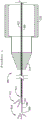
Fig. 34, 35 and 36 illustrate another example of a microsurgical instrument having a positioner configured to extend and retract a composite microcannula through the lumen of a trocar. The locator 400 is configured to attach the trocar 200 to the distal end 418 of the handpiece 420. The composite microcannula 300 is passed through the lumen of the trocar 300 and the handpiece 420, wherein the microcannula is coupled to an insert 488 that is slidably engaged with the handpiece 420. As explained in more detail below, sliding the actuator 424 in the slot 428 on the handpiece 420 a selected distance 484 causes the composite microcannula to correspondingly displace relative to the end of the hollow rigid shaft 206 of the trocar by a distance 486 that is equal to twice the displacement distance 484 of the actuator. The trocar 200 and composite microcannula 300 may be provided separately from the positioner 400 and may be removable for replacement in the event that the trocar or microcannula is damaged or otherwise unavailable for use in a particular surgical procedure.
The two cross-sectional views of fig. 36 illustrate some of the internal features of the exemplary positioner 400 of fig. 34. Section H-H of fig. 36 shows the actuator 424 retracted toward the proximal end 416 of the handpiece 420. Section J-J shows the actuator traveling toward the distal end 418 of the handpiece 420. The two views of the handpiece 420 in fig. 36 are referenced to each other so that the position of the internal components can be accurately compared between the sections.
The insert 488 slidably engages an inner surface of a void formed within the handpiece 420. The actuator 424 travels along one or more guide ridges 430. A U-shaped hollow tube 492 attached to the actuator 424 moves with the actuator. The insertion shift wire 490 slidably passes through the lumen of the U-shaped hollow tube 492. One end of the insert shift wire 490 is attached to the insert 488. The opposite end of the insertion shift wire 490 is attached to an anchor post 494 that is fixedly attached to the handpiece 420 or alternatively formed as an integral part thereof. The insertion displacement wire 490 is preferably flexible enough to easily slide around the bend of the U-shaped hollow tube 492, yet stiff enough to push the insert 488 in the distal direction (i.e., away from the trocar 200) when the actuator is displaced in the distal direction.
With one end of the insert displacement wire 490 secured to the handpiece at the anchor post 494 and the other end of the wire secured to the insert 488, sliding displacement of the actuator 424 a distance "d"484 along the handpiece causes the U-shaped hollow tube 492 to be displaced the same distance "d" and the insert 488 to be displaced twice (2 x d), represented in the drawings by the relative displacement 486 of the insert between sections H-H and K-K. The composite microcannula 300 is sufficiently securely coupled to the insert 488 to hold the composite microcannula stationary relative to the insert as the actuator moves relative to the handpiece. Since the insert displaces the actuator twice the displacement distance 484, the composite microcannula also displaces the actuator twice the displacement distance 484. The actuator is moved proximally a distance "d"484 to extend the composite microcannula a distance "2x d"486 from the trocar. The actuator is moved distally a distance "d" to retract the composite microcannula a distance "2x d".
The composite microcannula 300 may be passed through a hollow cannula having a fixation section 436 attached to or alternatively formed as an integral part of the hollow rigid shaft 206 of the trocar 200. The movable section 434 of the hollow sleeve is slidably engaged with the fixed section 436 at one end and attached to the insert 488 at the other end. The hollow cannula limits lateral deflection of the composite microcannula as the actuator advances and retracts, forcing the composite microcannula to advance and retract without kinking or significantly bending within the handpiece.
As suggested by the example of fig. 36, the composite microcannula 300 may extend outwardly from the proximal end 416 of the locator 400 and the insert 488. The proximal extension of the composite microcannula may be configured to receive a solid and/or liquid payload, a surgical instrument, and one or more optical fibers, as previously described.
Unless explicitly stated otherwise herein, ordinary terms have their corresponding ordinary meanings within the respective contexts of their representations, and ordinary terms in the art have their corresponding ordinary meanings.
Claims (17)
1. An ophthalmic microsurgical instrument comprising:
a hand piece;
an actuator slidably coupled to the handpiece;
an insert slidably coupled to the handpiece;
a hollow tube attached to the actuator, the hollow tube being generally U-shaped; and
a wire passing through the hollow tube, a first end of the wire being attached to the handpiece and a second end of the wire being attached to the insert;
a trocar attached to the handpiece;
a composite microcannula passing through the lumen of the trocar and coupled to the insert.
2. The ophthalmic microsurgical instrument of claim 1, further comprising:
The trocar has a hollow rigid shaft; and
a movable cannula slidably engaged with the hollow rigid shaft, the movable cannula attached to the insert, and the composite microcannula passing through the movable cannula.
3. The ophthalmic microsurgical instrument of claim 1, further comprising:
the trocar includes a rigid shaft having a proximal end and a distal end, the rigid shaft defining a lumen extending from the proximal end to the distal end, the distal end being shaped for tissue penetration; and
a composite microcannula positioned in the lumen, the composite microcannula comprising:
a flexible hollow tube having an outer diameter less than an inner diameter of the lumen; and
a light guide coupled to the flexible hollow tube.
4. The ophthalmic microsurgical instrument of claim 3, further comprising a locator configured to hold the composite microcannula.
5. The ophthalmic microsurgical instrument of claim 4, wherein the locator is configured to displace the composite microcannula relative to the trocar.
6. The ophthalmic microsurgical instrument of claim 4, wherein the locator is configured to hold the composite microcannula stationary relative to the trocar.
7. The ophthalmic microsurgical instrument of claim 4, further comprising a hollow cannula through which the composite microcannula passes.
8. The ophthalmic microsurgical instrument of claim 7, wherein the length of the hollow cannula varies with displacement of the composite microcannula relative to the trocar.
9. The ophthalmic microsurgical instrument of claim 4, wherein the composite microcannula is secured to the locator.
10. The ophthalmic microsurgical instrument of claim 4, wherein the locator is configured to slidingly contact the composite microcannula.
11. The ophthalmic microsurgical instrument of claim 3, further comprising a light source positioned to direct light into the light guide for illuminating a distal end of the light guide.
12. The ophthalmic microsurgical instrument of claim 3, further comprising a second light guide positioned to illuminate the distal end of the trocar.
13. The ophthalmic microsurgical instrument of claim 3, wherein the proximal end of the composite microcannula is in fluid communication with the distal end of the composite microcannula.
14. The ophthalmic microsurgical instrument of claim 3, wherein the composite microcannula is configured to admit a solid payload into the flexible hollow tube.
15. The ophthalmic microsurgical instrument of claim 3, the light guide comprising a layer of material disposed concentrically around a void space within the flexible hollow tube.
16. The ophthalmic microsurgical instrument of claim 1, the trocar further comprising:
a hollow rigid shaft, a distal end of the hollow rigid shaft being shaped for tissue penetration, the shaft being formed with a lumen extending from the distal end to a proximal end of the shaft;
a transition structure attached to the proximal end, the transition structure formed with a hole for allowing a composite microcannula to enter the lumen;
a light source positioned to illuminate the distal end; and
a smoothed distal edge of the lumen.
17. The ophthalmic microsurgical instrument of claim 16, the trocar further comprising: a finger grip extending outwardly from the transition structure.
Priority Applications (3)
| Application Number | Priority Date | Filing Date | Title |
|---|---|---|---|
| CN202310539242.7A CN116459072A (en) | 2017-10-18 | 2018-10-18 | Ophthalmic microsurgical instrument |
| CN202310538399.8A CN116585096A (en) | 2017-10-18 | 2018-10-18 | Ophthalmic microsurgical instrument |
| CN202310540432.0A CN116459073A (en) | 2017-10-18 | 2018-10-18 | Ophthalmic microsurgical instrument |
Applications Claiming Priority (7)
| Application Number | Priority Date | Filing Date | Title |
|---|---|---|---|
| US201762574136P | 2017-10-18 | 2017-10-18 | |
| US62/574,136 | 2017-10-18 | ||
| US15/892,833 | 2018-02-09 | ||
| US15/892,833 US10987247B2 (en) | 2017-10-18 | 2018-02-09 | Opthalmic microsurgical instrument |
| US16/145,119 US11576816B2 (en) | 2017-10-18 | 2018-09-27 | Opthalmic microsurgical instrument |
| US16/145,119 | 2018-09-27 | ||
| PCT/US2018/056433 WO2019079544A1 (en) | 2017-10-18 | 2018-10-18 | Opthalmic microsurgical instrument |
Related Child Applications (3)
| Application Number | Title | Priority Date | Filing Date |
|---|---|---|---|
| CN202310539242.7A Division CN116459072A (en) | 2017-10-18 | 2018-10-18 | Ophthalmic microsurgical instrument |
| CN202310540432.0A Division CN116459073A (en) | 2017-10-18 | 2018-10-18 | Ophthalmic microsurgical instrument |
| CN202310538399.8A Division CN116585096A (en) | 2017-10-18 | 2018-10-18 | Ophthalmic microsurgical instrument |
Publications (2)
| Publication Number | Publication Date |
|---|---|
| CN111936091A CN111936091A (en) | 2020-11-13 |
| CN111936091B true CN111936091B (en) | 2023-06-06 |
Family
ID=66097661
Family Applications (4)
| Application Number | Title | Priority Date | Filing Date |
|---|---|---|---|
| CN202310540432.0A Pending CN116459073A (en) | 2017-10-18 | 2018-10-18 | Ophthalmic microsurgical instrument |
| CN201880075174.0A Active CN111936091B (en) | 2017-10-18 | 2018-10-18 | Ophthalmic microsurgical instrument |
| CN202310539242.7A Pending CN116459072A (en) | 2017-10-18 | 2018-10-18 | Ophthalmic microsurgical instrument |
| CN202310538399.8A Pending CN116585096A (en) | 2017-10-18 | 2018-10-18 | Ophthalmic microsurgical instrument |
Family Applications Before (1)
| Application Number | Title | Priority Date | Filing Date |
|---|---|---|---|
| CN202310540432.0A Pending CN116459073A (en) | 2017-10-18 | 2018-10-18 | Ophthalmic microsurgical instrument |
Family Applications After (2)
| Application Number | Title | Priority Date | Filing Date |
|---|---|---|---|
| CN202310539242.7A Pending CN116459072A (en) | 2017-10-18 | 2018-10-18 | Ophthalmic microsurgical instrument |
| CN202310538399.8A Pending CN116585096A (en) | 2017-10-18 | 2018-10-18 | Ophthalmic microsurgical instrument |
Country Status (7)
| Country | Link |
|---|---|
| US (1) | US11576816B2 (en) |
| EP (1) | EP3697353A1 (en) |
| JP (4) | JP7370990B2 (en) |
| CN (4) | CN116459073A (en) |
| AU (2) | AU2018353126A1 (en) |
| DE (1) | DE112018004635T5 (en) |
| WO (1) | WO2019079544A1 (en) |
Families Citing this family (2)
| Publication number | Priority date | Publication date | Assignee | Title |
|---|---|---|---|---|
| US10987247B2 (en) * | 2017-10-18 | 2021-04-27 | Jesus Moreno | Opthalmic microsurgical instrument |
| US20230181363A1 (en) * | 2018-09-27 | 2023-06-15 | Nova Eye, Inc. | Opthalmic microsurgical instrument |
Citations (7)
| Publication number | Priority date | Publication date | Assignee | Title |
|---|---|---|---|---|
| US5460182A (en) * | 1992-09-14 | 1995-10-24 | Sextant Medical Corporation | Tissue penetrating apparatus and methods |
| WO1995032663A1 (en) * | 1994-06-01 | 1995-12-07 | Kieturakis Maciej J | Instrument and method for performing surgery around a viewing space in the interior of the body |
| CN1398173A (en) * | 2000-01-18 | 2003-02-19 | 伊西康内外科公司 | Laparoscopic access tool with gas seal |
| CN1909859A (en) * | 2004-01-23 | 2007-02-07 | 伊萨恩斯外科手术股份有限公司 | Composite ophthalmic microcannula |
| CN101426473A (en) * | 2006-02-22 | 2009-05-06 | I科学干预公司 | Be used for instrument and preparation that suprachoroid medicine is sent |
| CN106687078A (en) * | 2014-02-12 | 2017-05-17 | 伊西康内外科有限责任公司 | Method and apparatus for suprachoroidal administration of therapeutic agent |
| CN107174398A (en) * | 2017-05-27 | 2017-09-19 | 天津优视眼科技术有限公司 | A kind of luminous trochar of ophthalmology and its application method |
Family Cites Families (27)
| Publication number | Priority date | Publication date | Assignee | Title |
|---|---|---|---|---|
| JPH01293312A (en) * | 1988-05-10 | 1989-11-27 | Trimedyne Inc | Fiber optic system |
| US6564087B1 (en) * | 1991-04-29 | 2003-05-13 | Massachusetts Institute Of Technology | Fiber optic needle probes for optical coherence tomography imaging |
| US5637097A (en) * | 1992-04-15 | 1997-06-10 | Yoon; Inbae | Penetrating instrument having an expandable anchoring portion |
| US5263937A (en) * | 1993-02-11 | 1993-11-23 | Shipp John I | Trocar with profile to reduce insertion force |
| US5647840A (en) * | 1994-09-14 | 1997-07-15 | Circon Corporation | Endoscope having a distally heated distal lens |
| US5517997A (en) * | 1994-09-15 | 1996-05-21 | Gabriel Medical, Inc. | Transillumination of body members for protection during body invasive procedures |
| DE19542955C2 (en) * | 1995-11-17 | 1999-02-18 | Schwind Gmbh & Co Kg Herbert | endoscope |
| US6936053B1 (en) * | 1998-07-02 | 2005-08-30 | Jeffrey N. Weiss | Ocular implant needle |
| KR100771149B1 (en) | 1999-12-10 | 2007-10-30 | 아이싸이언스 인터벤셔날 코포레이션 | Treatment of ocular disease |
| US7217263B2 (en) * | 2000-01-03 | 2007-05-15 | The Johns Hopkins University | Device and method for manual retinal vein catheterization |
| US7077848B1 (en) * | 2000-03-11 | 2006-07-18 | John Hopkins University | Sutureless occular surgical methods and instruments for use in such methods |
| KR100976186B1 (en) * | 2001-11-21 | 2010-08-17 | 아이싸이언스 코포레이션 | Ophthalmic microsurgical system |
| US7931596B2 (en) | 2002-07-12 | 2011-04-26 | Iscience Interventional Corporation | Ultrasound interfacing device for tissue imaging |
| EP1539066B1 (en) * | 2002-09-17 | 2012-11-07 | Iscience Surgical Corporation | Apparatus surgical bypass of aqueous humor |
| BRPI0506837A (en) | 2004-01-12 | 2007-06-12 | Iscience Surgical Corp | viscous material injector, and devices and kit for providing micro-quantities of viscous materials |
| US20100173866A1 (en) * | 2004-04-29 | 2010-07-08 | Iscience Interventional Corporation | Apparatus and method for ocular treatment |
| EP1833440B1 (en) | 2004-12-16 | 2012-08-22 | Iscience Interventional Corporation | Ophthalmic implant for treatment of glaucoma |
| ES2917876T3 (en) * | 2008-09-29 | 2022-07-12 | Applied Med Resources | First Entry Trocar System |
| US8425473B2 (en) | 2009-01-23 | 2013-04-23 | Iscience Interventional Corporation | Subretinal access device |
| JP5551395B2 (en) * | 2009-08-28 | 2014-07-16 | マニー株式会社 | Cannula and manufacturing method thereof |
| EP2575715B1 (en) | 2010-05-27 | 2014-10-29 | Ellex-iScience, Inc. | Device for placing circumferential implant in schlemm's canal |
| US9554940B2 (en) * | 2012-03-26 | 2017-01-31 | Glaukos Corporation | System and method for delivering multiple ocular implants |
| US20160081712A1 (en) * | 2013-04-29 | 2016-03-24 | The Charltte-Mecklenburg Hospital Authority D/B/A Carolinas Healthcare System | Device, system, and method for insertion of a medical device into a subject |
| EP2818127B1 (en) * | 2013-06-20 | 2016-03-16 | Erbe Elektromedizin GmbH | Electrosurgical instrument with light guide |
| CA2987330A1 (en) * | 2015-06-02 | 2016-12-08 | Becton, Dickinson And Company | Tissue removal device and method of use |
| US9980817B2 (en) * | 2015-10-08 | 2018-05-29 | Shlomo Gabbay | Method and device for crimping and loading heart valve |
| US10987247B2 (en) * | 2017-10-18 | 2021-04-27 | Jesus Moreno | Opthalmic microsurgical instrument |
-
2018
- 2018-09-27 US US16/145,119 patent/US11576816B2/en active Active
- 2018-10-18 JP JP2020542704A patent/JP7370990B2/en active Active
- 2018-10-18 CN CN202310540432.0A patent/CN116459073A/en active Pending
- 2018-10-18 CN CN201880075174.0A patent/CN111936091B/en active Active
- 2018-10-18 CN CN202310539242.7A patent/CN116459072A/en active Pending
- 2018-10-18 AU AU2018353126A patent/AU2018353126A1/en not_active Abandoned
- 2018-10-18 WO PCT/US2018/056433 patent/WO2019079544A1/en unknown
- 2018-10-18 DE DE112018004635.4T patent/DE112018004635T5/en active Pending
- 2018-10-18 CN CN202310538399.8A patent/CN116585096A/en active Pending
- 2018-10-18 EP EP18804436.6A patent/EP3697353A1/en active Pending
-
2022
- 2022-11-30 AU AU2022279455A patent/AU2022279455A1/en active Pending
-
2023
- 2023-10-18 JP JP2023179783A patent/JP2024016059A/en active Pending
- 2023-10-18 JP JP2023179782A patent/JP2024016058A/en active Pending
- 2023-10-18 JP JP2023179781A patent/JP2024016057A/en active Pending
Patent Citations (7)
| Publication number | Priority date | Publication date | Assignee | Title |
|---|---|---|---|---|
| US5460182A (en) * | 1992-09-14 | 1995-10-24 | Sextant Medical Corporation | Tissue penetrating apparatus and methods |
| WO1995032663A1 (en) * | 1994-06-01 | 1995-12-07 | Kieturakis Maciej J | Instrument and method for performing surgery around a viewing space in the interior of the body |
| CN1398173A (en) * | 2000-01-18 | 2003-02-19 | 伊西康内外科公司 | Laparoscopic access tool with gas seal |
| CN1909859A (en) * | 2004-01-23 | 2007-02-07 | 伊萨恩斯外科手术股份有限公司 | Composite ophthalmic microcannula |
| CN101426473A (en) * | 2006-02-22 | 2009-05-06 | I科学干预公司 | Be used for instrument and preparation that suprachoroid medicine is sent |
| CN106687078A (en) * | 2014-02-12 | 2017-05-17 | 伊西康内外科有限责任公司 | Method and apparatus for suprachoroidal administration of therapeutic agent |
| CN107174398A (en) * | 2017-05-27 | 2017-09-19 | 天津优视眼科技术有限公司 | A kind of luminous trochar of ophthalmology and its application method |
Also Published As
| Publication number | Publication date |
|---|---|
| EP3697353A1 (en) | 2020-08-26 |
| CN116585096A (en) | 2023-08-15 |
| JP2024016057A (en) | 2024-02-06 |
| CN111936091A (en) | 2020-11-13 |
| DE112018004635T5 (en) | 2020-07-16 |
| US11576816B2 (en) | 2023-02-14 |
| JP2024016058A (en) | 2024-02-06 |
| CN116459072A (en) | 2023-07-21 |
| AU2022279455A1 (en) | 2023-02-02 |
| AU2018353126A1 (en) | 2020-05-07 |
| JP7370990B2 (en) | 2023-10-30 |
| CN116459073A (en) | 2023-07-21 |
| US20190110925A1 (en) | 2019-04-18 |
| WO2019079544A1 (en) | 2019-04-25 |
| JP2021500198A (en) | 2021-01-07 |
| JP2024016059A (en) | 2024-02-06 |
Similar Documents
| Publication | Publication Date | Title |
|---|---|---|
| US11564835B2 (en) | Opthalmic microsurgical instrument | |
| US11723798B2 (en) | Sub-retinal tangential needle catheter guide and introducer | |
| US8491549B2 (en) | Ophthalmic microsurgical system | |
| EP1615604B1 (en) | Opthalmic microsurgical instruments | |
| US20110282190A1 (en) | Combined endoscopic surgical tools | |
| JP2024016058A (en) | Ophthalmic microsurgical instruments | |
| US20110125139A1 (en) | Multi-fiber flexible surgical probe | |
| KR20130008556A (en) | Multi-fiber flexible surgical probe | |
| JP2021500198A5 (en) | ||
| US20230181363A1 (en) | Opthalmic microsurgical instrument | |
| US11696852B2 (en) | Ophthalmic surgical instrument | |
| AU2013276988A1 (en) | Composite Ophthalmic Microcannula |
Legal Events
| Date | Code | Title | Description |
|---|---|---|---|
| PB01 | Publication | ||
| PB01 | Publication | ||
| SE01 | Entry into force of request for substantive examination | ||
| SE01 | Entry into force of request for substantive examination | ||
| TA01 | Transfer of patent application right | ||
| TA01 | Transfer of patent application right |
Effective date of registration: 20210113 Address after: California, USA Applicant after: Xinmou Co.,Ltd. Address before: California, USA Applicant before: J. Moreno Applicant before: P. Prosser |
|
| GR01 | Patent grant | ||
| GR01 | Patent grant |