A high-efficient heat abstractor for outdoor transformer
Technical Field
The invention belongs to the technical field of outdoor transformers, and particularly relates to a high-efficiency heat dissipation device for an outdoor transformer.
Background
A transformer is a device that changes an alternating voltage using the principle of electromagnetic induction, and main components are a primary coil, a secondary coil, and an iron core (magnetic core). The main functions are as follows: voltage transformation, current transformation, impedance transformation, isolation, voltage stabilization (magnetic saturation transformer), and the like. According to the application, the method can be divided into: power transformers and special transformers (furnace transformers, rectification transformers, power frequency test transformers, voltage regulators, mining transformers, audio transformers, intermediate frequency transformers, high frequency transformers, impact transformers, instrument transformers, electronic transformers, reactors, mutual inductors, etc.).
In the using process of the transformer, a large amount of high temperature can be generated, if the transformer cannot be timely cooled, the transformer can be damaged seriously, and the economic loss caused by fire can be caused.
For example, application No.: 201510783280.2, the invention discloses a high-efficiency transformer heat dissipation device, which comprises a heat dissipation chamber, a heat dissipation fan, an oil tank, an oil guide pipe, a sun-proof cover, a heat conduction pipe and a heat dissipation fin, wherein the heat dissipation fan and the heat dissipation fin are arranged outside the heat dissipation chamber, the heat conduction pipe, the oil tank and the oil guide pipe are arranged inside the heat dissipation chamber, the sun-proof cover is arranged on the top of the heat dissipation chamber, the heat dissipation fin is connected with the oil tank through the oil guide pipe, the heat dissipation fin is connected with the heat conduction pipe, the heat conduction pipe abuts against a transformer, and a door is arranged on one side. This high-efficient transformer heat abstractor is last not only to be equipped with the fin, still is equipped with radiator fan, can be very fast distribute away the heat that the transformer sent, even also can be with the temperature control of transformer in certain scope summer, has fine popularization nature.
Based on the above patent search, and the discovery of the devices in the prior art, when the above devices are used, although the heat generated by the transformer can be dissipated by the heat dissipation fan, the above devices are limited by the use environment, and therefore, the heat dissipation operation cannot be performed at any place, for example, the heat dissipated by the heat dissipation fan in the environment with high temperature cannot satisfy the heat dissipation operation of the transformer, but the heat is absorbed from the outside during blowing, so that the heat inside the transformer is accumulated, and the transformer is damaged.
Disclosure of Invention
In order to solve the above technical problems, the present invention provides an efficient heat dissipation apparatus for an outdoor transformer, which is used to solve the problem that although the heat generated by the transformer can be dissipated by a heat dissipation fan, the heat dissipation apparatus is limited by the use environment and thus cannot perform a good heat dissipation operation anywhere, for example, the heat dissipated by a heat dissipation fan in an environment with a high temperature cannot satisfy the heat dissipation operation of the transformer, but the heat may be absorbed from the outside during blowing, which may cause the accumulation of the heat inside the transformer, thereby causing the damage of the transformer.
The invention relates to a purpose and an effect of a high-efficiency heat dissipation device for an outdoor transformer, which are achieved by the following specific technical means:
a high-efficiency heat dissipation device for an outdoor transformer comprises a side protection heat dissipation cover, a water cooling mechanism, a transformer base, a water cooling auxiliary mechanism, an upper cover plate and a side heat dissipation mechanism, wherein the side protection heat dissipation cover is provided with two positions which are respectively and axially connected with the left end surface and the right end surface of the transformer; the water cooling mechanism is fixedly connected to the rear side position inside the transformer; the transformer base is fixedly connected to the bottom end face of the transformer, and the left side and the right side of the bottom end face of the transformer base are screwed with supporting columns with the same size; the water-cooling auxiliary mechanism is fixedly connected to the rear side position of the top end face of the transformer base, and the installation position of the water-cooling auxiliary mechanism is located at the rear side position of the water-cooling mechanism; the water cooling mechanism comprises a refrigeration base, refrigeration base slots, first fixing bolts, through columns, water cooling copper pipes and a water tank, wherein the refrigeration base slots with the same size are symmetrically arranged at the left side and the right side of the interior of the refrigeration base, the first fixing bolts are screwed on the opposite surfaces of the two refrigeration base slots, the through columns are arranged at two positions, the two through columns are respectively connected to the left side and the right side of the top end face of the refrigeration base in a through mode, the water cooling copper pipes are connected to the inner sides of the two through columns in a through mode, the water tank is connected to the top ends of the two through columns in a through mode, and in the installation state, the refrigeration base is screwed on the inner position of the rear heat dissipation cover through the rear heat dissipation through holes after the refrigeration base slots arranged at the left side and the right side are clamped with the supporting plate through the first fixing bolts; the upper cover plate is screwed on the top end surface of the rear heat dissipation cover; the side heat dissipation mechanisms are arranged at two positions, and the two side heat dissipation mechanisms are respectively and fixedly connected to the inner positions of the two side protection heat dissipation covers.
Furthermore, the side protection heat dissipation cover comprises a cover door, a cover body rotating shaft, three heat dissipation boxes, side heat dissipation nets, a handle and a built-in lock, wherein the cover body rotating shaft is connected to the right end face of the cover door in a shaft mode, the three heat dissipation boxes are arranged in three positions, the three heat dissipation boxes are connected to the front end face of the cover door in a straight line array mode in a penetrating mode, the front ends of the inner walls of the three heat dissipation boxes are fixedly connected with the side heat dissipation nets in the same size, the handle is fixedly connected to the center of the left side of the front end face of the cover door, the built-in lock is installed at the position under the handle, and the two cover doors are respectively connected to the inner positions of the left side face and the right side face of the transformer in a shaft;
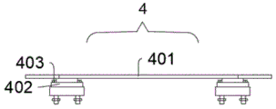
furthermore, the transformer base comprises a bottom plate, support legs, support leg bolts and support leg side through holes, the support legs are provided with two positions, the two support legs are fixedly connected to the left side and the right side of the bottom end face of the bottom plate respectively, the support leg bolts are provided with four positions, each two support leg bolts are in one group, two groups of support leg bolts are screwed at the rear side positions of the top end faces of the two support legs respectively, the two support legs are provided with two positions, the left side face and the right side face of each support leg are symmetrically provided with the support leg side through holes with the same size, and the support legs are embedded into the sliding grooves in the installation state and are screwed with the sliding grooves through the support leg bolts;
furthermore, the supporting column comprises a similar triangular column body, supporting column limiting plates, limiting plate through holes, sliding grooves and supporting column fixing bolts, the top end face of the similar triangular column body is fixedly connected with the sliding grooves, the left side and the right side of the top end face of the sliding grooves are fixedly connected with the supporting column limiting plates with the same size, the limiting plate through holes with the same size are symmetrically formed in the two supporting column limiting plates, the supporting column fixing bolts are screwed in the limiting plate through holes, and the supporting column penetrates through the limiting plate through holes and the supporting leg side through holes in sequence to be screwed in the outer side position of the transformer base in the mounting state;
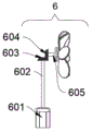
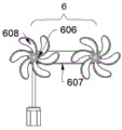
furthermore, the water-cooling auxiliary mechanism comprises a water-cooling auxiliary motor, a first water-cooling auxiliary transmission shaft, a first water-cooling bevel gear, a second water-cooling auxiliary transmission shaft, a transmission gear, a chain and a water-cooling fan, wherein the output end of the water-cooling auxiliary motor is connected with the first water-cooling auxiliary transmission shaft in a shaft mode, the first water-cooling bevel gear is fixedly connected to the top end face of the first water-cooling auxiliary transmission shaft and is in meshing transmission with the second water-cooling bevel gear on the front side so as to drive the single-side transmission gear to rotate through the second water-cooling auxiliary transmission shaft, the transmission gear is provided with two positions in total, the front ends of the transmission gear on the two positions are fixedly connected with the water-cooling fan with the same size, the chain is in meshing transmission on the outer peripheral face positions;
furthermore, the upper cover plate comprises an upper cover plate main body, an upper cover plate slot, an upper cover plate fixing bolt and a water pipe groove, the upper cover plate slot with the same size is symmetrically arranged on the left side and the right side of the bottom end face of the upper cover plate main body, the upper cover plate fixing bolt is screwed on the opposite face of the upper cover plate slot, the water pipe groove is designed in a square structure, the water pipe groove is respectively arranged on the left side and the right side of the inner part of the upper cover plate main body, the upper cover plate main body is inserted into the top ends of the two rear side plates through the upper cover plate slot in an installation state, and the upper cover plate main body penetrates through the rear heat dissipation through hole through the upper cover plate fixing bolt so as to screw the upper cover plate on the top end position of the rear heat dissipation cover.
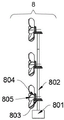
Furthermore, the side heat dissipation mechanism comprises a micro motor, a side transmission shaft, a first side helical gear, a second side helical gear and a side heat dissipation fan, wherein the output end of the micro motor is coupled with the side transmission shaft, the first side helical gear is provided with three positions, the three positions of the first side helical gear are fixedly connected to the outer peripheral surface of the side transmission shaft in a linear array manner, the three positions of the first side helical gear are meshed with the second side helical gear on the left side for transmission so as to drive the three positions of the side heat dissipation fan to synchronously rotate, and the side heat dissipation fan is coupled to the inner position of the heat dissipation box through the side transmission shaft in the installation state;
further, the rear heat dissipation cover is including posterior lateral plate, back filter screen, layer board and rear heat dissipation through-hole, the posterior lateral plate is equipped with two altogether, and two the posterior lateral plate is fixed connection respectively in the top face left side and the right side position of layer board, back filter screen fixed connection is located the rear side position of layer board top face in the inboard position and the mounted position of two posterior lateral plates, and two the same size's rear heat dissipation through-hole has all been seted up to the inside top and the bottom of posterior lateral plate.
Compared with the prior art, the invention has the following beneficial effects:
when the transformer is installed, the support legs in the transformer base can be adjusted according to actual needs to drive the bottom plate and the transformer to slide in the sliding groove so as to adjust the distance between the transformer and the support according to actual needs, and after the transformer is powered on, the micro motor in the side radiating mechanism can gradually drive the side radiating fan to rotate through the side transmission shaft connected with the output end in a shaft way so as to discharge the heat in the transformer in time, and when the side radiating mechanism or components in the transformer need to be overhauled in the later period, the hidden lock can be opened by pulling the handle to open the cover door to rotate around the rotating shaft of the cover body, the hidden lock can play the roles of preventing theft and damage under the normally closed state, and simultaneously, a proper amount of water can be added into the water tank in the water cooling mechanism for better radiating effect, the water cooling copper pipe is continuously and circularly fed with water through the two through stand columns after being refrigerated by the refrigeration base, so that the purpose of continuously absorbing a part of heat generated in the transformer and then quickly discharging the heat through the rear filter screen in the rear heat dissipation cover is achieved, the dual heat dissipation and the active heat dissipation under the high-temperature environment are achieved, meanwhile, the water cooling auxiliary motor in the water cooling auxiliary mechanism can be selectively started for better heat dissipation effect, the single-side transmission gear is gradually driven to rotate through the first water cooling auxiliary transmission shaft connected with the output end in a shaft mode, then the two water cooling fans are synchronously driven through the chain to continuously blow the water cooling copper pipe, and the purpose of actively dissipating heat of the transformer by blowing cold air of the water cooling copper pipe is achieved.
Drawings
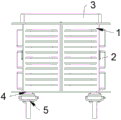
FIG. 1 is a side view of the present invention.
Fig. 2 is a left side view of the present invention.
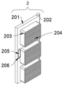
Fig. 3 is a schematic structural view of the side shield heat dissipation cover of the present invention.
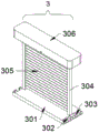
Fig. 4 is a schematic structural view of the water cooling mechanism of the present invention.
Fig. 5 is a schematic front view of the transformer base according to the present invention.
Fig. 6 is a schematic side view of the transformer base of the present invention.
Fig. 7 is a schematic view of the strut structure of the present invention.
Fig. 8 is a schematic side view of the water cooling assist mechanism of the present invention.
Fig. 9 is a schematic front view of the water cooling assist mechanism of the present invention.
Fig. 10 is a schematic view of the structure of the upper cover plate of the present invention.
Fig. 11 is a schematic structural view of a side heat dissipation mechanism according to the present invention.
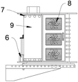
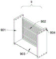
Fig. 12 is a schematic structural diagram of the rear heat dissipation cover of the present invention.
In the drawings, the corresponding relationship between the component names and the reference numbers is as follows:
1. a transformer; 2. a side protection heat dissipation cover; 201. a cover door; 202. a cover body rotating shaft; 203. a heat dissipation box; 204. a side heat-dissipating net; 205. a handle; 206. a built-in lock; 3. a water cooling mechanism; 301. a refrigeration base; 302. a refrigeration base slot; 303. a first fixing bolt; 304. penetrating the upright post; 305. water-cooling the copper pipe; 306. a water tank; 4. a transformer base; 401. a base plate; 402. a support leg; 403. a leg bolt; 404. a leg side through hole; 5. a pillar; 501. a triangular cylinder-like body; 502. a strut limiting plate; 503. a limiting plate through hole; 504. a chute; 505. a strut fixing bolt; 6. a water-cooling auxiliary mechanism; 601. a water-cooled auxiliary motor; 602. a first water-cooled auxiliary transmission shaft; 603. a first water-cooled helical gear; 604. a second water-cooled helical gear; 605. a second water-cooled auxiliary transmission shaft; 606. a transmission gear; 607. a chain; 608. a water cooling fan; 7. an upper cover plate; 701. an upper cover plate main body; 702. an upper cover plate slot; 703. an upper cover plate fixing bolt; 704. a water pipe groove; 8. a side heat dissipation mechanism; 801. a micro motor; 802. a side transmission shaft; 803. a first side bevel gear; 804. a second side bevel gear; 805. a side heat radiation fan; 9. a rear heat dissipation cover; 901. a rear side plate; 902. a rear filter screen; 903. a support plate; 904. and a rear heat dissipation through hole.
Detailed Description
The embodiments of the present invention will be described in further detail with reference to the drawings and examples. The following examples are intended to illustrate the invention but are not intended to limit the scope of the invention.
As shown in figures 1 to 12:
the invention provides a high-efficiency heat dissipation device for an outdoor transformer, which comprises: the side protection heat dissipation cover comprises a side protection heat dissipation cover 2, a water cooling mechanism 3, a transformer base 4, a water cooling auxiliary mechanism 6, an upper cover plate 7 and a side heat dissipation mechanism 8, wherein the side protection heat dissipation cover 2 is provided with two positions, and the two side protection heat dissipation covers 2 are respectively and axially connected to the left end surface and the right end surface of the transformer 1; the water cooling mechanism 3 is fixedly connected to the rear side position inside the transformer 1; the transformer base 4 is fixedly connected to the bottom end face of the transformer 1, and the left side and the right side of the bottom end face of the transformer base 4 are screwed with the pillars 5 with the same size; the water-cooling auxiliary mechanism 6 is fixedly connected to the rear side position of the top end face of the transformer base 4, and the installation position of the water-cooling auxiliary mechanism 6 is located at the rear side position of the water-cooling mechanism 3; the water cooling mechanism 3 comprises a refrigeration base 301, a refrigeration base slot 302, a first fixing bolt 303, a through upright column 304, a water cooling copper pipe 305 and a water tank 306, the refrigeration base slot 302 with the same size is symmetrically arranged at the left side and the right side of the interior of the refrigeration base 301, and the opposite surfaces of the two refrigeration base slots 302 are respectively screwed with a first fixing bolt 303, two through upright posts 304 are arranged, and two through upright posts 304 are respectively connected at the left side and the right side of the top end surface of the refrigeration base 301 in a through way, the inner sides of the two through columns 304 are connected with water-cooling copper pipes 305 in a through mode, the water tank 306 is connected to the top ends of the two through columns 304 in a through mode, and in the installation state, the refrigeration base 301 is clamped with the supporting plate 903 through the refrigeration base slots 302 formed in the left side and the right side and then penetrates through the rear heat dissipation through hole 904 through the first fixing bolt 303 to enable the water-cooling mechanism 3 to be screwed to the inner position of the rear heat dissipation cover 9; the upper cover plate 7 is screwed on the top end surface of the rear heat dissipation cover 9; the side heat dissipation mechanism 8 has two positions, and the two side heat dissipation mechanisms 8 are respectively and fixedly connected to the inner positions of the two side protection heat dissipation covers 2.
Wherein, the side protection heat radiation shield 2 comprises a shield door 201, a shield body rotating shaft 202, a heat radiation box 203, a side heat radiation net 204, a handle 205 and a built-in lock 206, the right end surface of the shield door 201 is connected with the shield body rotating shaft 202 in a shaft way, the heat radiation box 203 is provided with three positions, and three heat dissipation boxes 203 are connected in a linear array penetrating at the front end surface of the cover door 201, the front ends of the inner walls of the three radiating boxes 203 are fixedly connected with side radiating nets 204 with the same size, a handle 205 is fixedly connected with the left center position of the front end surface of the cover door 201, a built-in lock 206 is arranged right below the handle 205, the two cover doors 201 are respectively and axially connected with the inner positions of the left side surface and the right side surface of the transformer 1 through cover body rotating shafts 202 in the installation state, wherein the cover door 201 can be reinforced by the built-in lock 206 under the normal close state to achieve the purpose of preventing damage, and the cover door 201 can be opened through the handle 205 quickly during the maintenance or overhaul process to achieve the purpose of more practical use.
Wherein, the transformer base 4 includes the bottom plate 401, the stabilizer blade 402, the stabilizer blade bolt 403 and the stabilizer blade side through-hole 404, the stabilizer blade 402 is equipped with two places altogether, and two places stabilizer blade 402 is fixed connection respectively in bottom end face left side and right side position of bottom plate 401, the stabilizer blade bolt 403 is equipped with four places altogether, wherein per two places stabilizer blade bolt 403 is a set of, and two sets of stabilizer blade bolts 403 are screwed respectively in the top end face rear side position of two places stabilizer blade 402, the stabilizer blade 402 is equipped with two places altogether, and the same size stabilizer blade side through-hole 404 has all been seted up to the bilateral surface symmetry of two places stabilizer blade 402, the stabilizer blade 402 is embedded into the inside of spout 504 and is screwed with stabilizer blade 402 and spout 504 mutually through stabilizer blade bolt 403 under the installation state, in order to play the better.
The strut 5 comprises a similar triangular cylinder 501, strut limiting plates 502, limiting plate through holes 503, sliding grooves 504 and strut fixing bolts 505, the top end face of the similar triangular cylinder 501 is fixedly connected with the sliding grooves 504, the left side and the right side of the top end face of each sliding groove 504 are fixedly connected with strut limiting plates 502 with the same size, the limiting plate through holes 503 with the same size are symmetrically formed in the two strut limiting plates 502, the strut fixing bolts 505 are screwed in the limiting plate through holes 503, the strut 5 sequentially penetrates through the limiting plate through holes 503 and the leg side through holes 404 through the strut fixing bolts 505 in an installation state to be screwed in the outer side positions of the transformer base 4, the transformer base 4 can slide and adjust the distance between the transformer 1 and a support according to actual needs.
Wherein, the water-cooling auxiliary mechanism 6 comprises a water-cooling auxiliary motor 601, a first water-cooling auxiliary transmission shaft 602, a first water-cooling bevel gear 603, a second water-cooling bevel gear 604, a second water-cooling auxiliary transmission shaft 605, a transmission gear 606, a chain 607 and a water-cooling fan 608, the output end of the water-cooling auxiliary motor 601 is coupled with the first water-cooling auxiliary transmission shaft 602, the first water-cooling bevel gear 603 is fixedly connected with the top end surface of the first water-cooling auxiliary transmission shaft 602 and is engaged with the second water-cooling bevel gear 604 at the front side for driving the single-side transmission gear 606 to rotate through the second water-cooling auxiliary transmission shaft 605, the transmission gear 606 is provided with two positions in total, the front ends of the transmission gears 606 are fixedly connected with the water-cooling fan 608 with the same size, the chain 607 is engaged with the peripheral surface positions of the transmission gears 606 at the two positions, the cold air can be blown to the water-cooling copper pipe 305 arranged in the water-cooling mechanism 3 by the water-cooling fan 608 to enter the interior of the transformer 1 quickly to achieve the purpose of quick heat dissipation and temperature reduction.
The upper cover plate 7 comprises an upper cover plate main body 701, upper cover plate slots 702, upper cover plate fixing bolts 703 and water pipe slots 704, the upper cover plate slots 702 with the same size are symmetrically arranged on the left side and the right side of the bottom end face of the upper cover plate main body 701, the upper cover plate fixing bolts 703 are screwed on the opposite surfaces of the two upper cover plate slots 702, the water pipe slots 704 are designed in a square structure, the two water pipe slots 704 are respectively arranged on the left side and the right side inside the upper cover plate main body 701, the upper cover plate main body 701 is connected with the top ends of the two rear side plates 901 in an inserting mode through the upper cover plate slots 702 in the installation state, the upper cover plate main body 701 penetrates through the rear heat dissipation through holes 904 through the upper cover plate fixing bolts 703 to screw the upper cover plate 7 on the top end of the rear heat dissipation cover 9, and the whole sealing performance and firmness.
The side heat dissipation mechanism 8 includes a micro motor 801, a side transmission shaft 802, a first side bevel gear 803, a second side bevel gear 804, and a side heat dissipation fan 805, the output end of the micro motor 801 is coupled to the side transmission shaft 802, the first side bevel gear 803 has three positions, and the three positions of the first side bevel gear 803 are fixedly connected to the outer peripheral surface of the side transmission shaft 802 in a linear array manner, and the three positions of the first side bevel gear 803 are all meshed with the second side bevel gear 804 on the left side for transmission to drive the three positions of the side heat dissipation fan 805 to rotate synchronously, the side heat dissipation fan 805 is coupled to the internal position of the heat dissipation box 203 through the side transmission shaft 802 in the installation state, and the side heat dissipation fan 805 can be driven by the micro motor 801 to rotate to quickly discharge heat inside the.
Wherein, back heat dissipation cover 9 is including posterior lateral plate 901, back filter screen 902, layer board 903 and back heat dissipation through-hole 904, posterior lateral plate 901 is equipped with two places altogether, and two places posterior lateral plate 901 fixed connection respectively is in the top terminal surface left side and the right side position of layer board 903, back filter screen 902 fixed connection is in the inboard position of two places posterior lateral plate 901 and the rear side position that the mounted position is located layer board 903 top terminal surface, and the back heat dissipation through-hole 904 of equidimension has all been seted up to the inside top and the bottom of two places posterior lateral plate 901.
When in use: firstly, the transformer 1 is moved to a proper position, then the support legs 402 in the transformer base 4 are adjusted according to actual needs to drive the bottom plate 401 and the transformer 1 to slide in the sliding groove 504 to adjust the distance between the transformer 1 and a support according to actual needs, so as to achieve better heat dissipation, after the adjustment is finished, the support fixing bolts 505 sequentially pass through the limiting plate through holes 503 and the support leg side through holes 404 to fix the transformer 1, after the fixation is finished, the transformer 1 is powered on, after the power on, the micro motor 801 in the side heat dissipation mechanism 8 firstly drives the side heat dissipation fan 805 to rotate gradually through the side transmission shaft 802 axially connected with the output end so as to discharge the heat in the transformer 1 in time, and when the side heat dissipation mechanism 8 or components in the transformer 1 need to be overhauled at later stage, the cover door 201 can be opened around the cover body 202 by pulling the handle 205 after the hidden lock 206 is opened, the built-in lock 206 can achieve the purpose of theft prevention and damage prevention in a normally closed state, meanwhile, for better heat dissipation effect, a proper amount of water can be added into the water tank 306 in the water cooling mechanism 3, the water is cooled by the cooling base 301 and then continuously circulated to the water cooling copper pipe 305 through the two penetrating columns 304, so that the purpose of continuously absorbing a part of heat generated in the transformer 1 and then quickly discharging the heat through the rear filter screen 902 in the rear heat dissipation cover 9 is achieved, and for better heat dissipation effect, the water cooling auxiliary motor 601 in the water cooling auxiliary mechanism 6 can be selectively opened, the single-side transmission gear 606 is gradually driven to rotate through the first water cooling auxiliary transmission shaft 602 connected with the output end in a shaft manner, and then the two water cooling fans 608 are synchronously driven to continuously blow the water cooling copper pipe 305 through the chain 607, so that the purpose of actively dissipating heat of blowing the cold air of the water cooling copper pipe 305 to the transformer 1.
The embodiments of the present invention have been presented for purposes of illustration and description, and are not intended to be exhaustive or limited to the invention in the form disclosed. Many modifications and variations will be apparent to those of ordinary skill in the art. The embodiment was chosen and described in order to best explain the principles of the invention and the practical application, and to enable others of ordinary skill in the art to understand the invention for various embodiments with various modifications as are suited to the particular use contemplated.