CN111929552B - A GIS basin insulator partial discharge detection component and system - Google Patents
A GIS basin insulator partial discharge detection component and system Download PDFInfo
- Publication number
- CN111929552B CN111929552B CN202011029702.4A CN202011029702A CN111929552B CN 111929552 B CN111929552 B CN 111929552B CN 202011029702 A CN202011029702 A CN 202011029702A CN 111929552 B CN111929552 B CN 111929552B
- Authority
- CN
- China
- Prior art keywords
- optical fiber
- basin
- partial discharge
- flange
- light
- Prior art date
- Legal status (The legal status is an assumption and is not a legal conclusion. Google has not performed a legal analysis and makes no representation as to the accuracy of the status listed.)
- Active
Links
Images


Classifications
-
- G—PHYSICS
- G01—MEASURING; TESTING
- G01R—MEASURING ELECTRIC VARIABLES; MEASURING MAGNETIC VARIABLES
- G01R31/00—Arrangements for testing electric properties; Arrangements for locating electric faults; Arrangements for electrical testing characterised by what is being tested not provided for elsewhere
- G01R31/12—Testing dielectric strength or breakdown voltage ; Testing or monitoring effectiveness or level of insulation, e.g. of a cable or of an apparatus, for example using partial discharge measurements; Electrostatic testing
- G01R31/1227—Testing dielectric strength or breakdown voltage ; Testing or monitoring effectiveness or level of insulation, e.g. of a cable or of an apparatus, for example using partial discharge measurements; Electrostatic testing of components, parts or materials
- G01R31/1245—Testing dielectric strength or breakdown voltage ; Testing or monitoring effectiveness or level of insulation, e.g. of a cable or of an apparatus, for example using partial discharge measurements; Electrostatic testing of components, parts or materials of line insulators or spacers, e.g. ceramic overhead line cap insulators; of insulators in HV bushings
-
- G—PHYSICS
- G01—MEASURING; TESTING
- G01R—MEASURING ELECTRIC VARIABLES; MEASURING MAGNETIC VARIABLES
- G01R31/00—Arrangements for testing electric properties; Arrangements for locating electric faults; Arrangements for electrical testing characterised by what is being tested not provided for elsewhere
- G01R31/12—Testing dielectric strength or breakdown voltage ; Testing or monitoring effectiveness or level of insulation, e.g. of a cable or of an apparatus, for example using partial discharge measurements; Electrostatic testing
- G01R31/1209—Testing dielectric strength or breakdown voltage ; Testing or monitoring effectiveness or level of insulation, e.g. of a cable or of an apparatus, for example using partial discharge measurements; Electrostatic testing using acoustic measurements
-
- G—PHYSICS
- G01—MEASURING; TESTING
- G01R—MEASURING ELECTRIC VARIABLES; MEASURING MAGNETIC VARIABLES
- G01R31/00—Arrangements for testing electric properties; Arrangements for locating electric faults; Arrangements for electrical testing characterised by what is being tested not provided for elsewhere
- G01R31/12—Testing dielectric strength or breakdown voltage ; Testing or monitoring effectiveness or level of insulation, e.g. of a cable or of an apparatus, for example using partial discharge measurements; Electrostatic testing
- G01R31/1218—Testing dielectric strength or breakdown voltage ; Testing or monitoring effectiveness or level of insulation, e.g. of a cable or of an apparatus, for example using partial discharge measurements; Electrostatic testing using optical methods; using charged particle, e.g. electron, beams or X-rays
Landscapes
- Physics & Mathematics (AREA)
- General Physics & Mathematics (AREA)
- Chemical & Material Sciences (AREA)
- Engineering & Computer Science (AREA)
- Ceramic Engineering (AREA)
- Acoustics & Sound (AREA)
- Testing Relating To Insulation (AREA)
Abstract
本发明提供了一种GIS盆式绝缘子局部放电检测组件及系统,包括:盆式绝缘子本体、传感光纤组件和连接法兰;传感光纤组件绕设在盆式绝缘子本体的外翻沿的外侧,传感光纤组件的第一端设置有光纤接头;传感光纤组件的第二端连接有光反射镜;连接法兰设置在所述盆式绝缘子本体的外翻沿上,连接法兰上设置有容置通道,用以将传感光纤组件卡设在盆式绝缘子本体的外翻沿与所述连接法兰之间,连接法兰的侧壁上开设有所述传感光纤组件的进线通道,所述光纤接头伸出所述进线通道。本发明使得局部放电缺陷产生的超声信号经盆式绝缘子本体作用于传感光纤组件上,充分减小了局放超声信号在气体中传播衰减对检测造成的不利影响,从而提高了局放的检测精度。
The invention provides a partial discharge detection component and system of a GIS basin-type insulator, comprising: a basin-type insulator body, a sensing optical fiber assembly and a connecting flange; the sensing optical fiber assembly is wound on the outside of the eversion edge of the basin-type insulator body , the first end of the sensing optical fiber assembly is provided with an optical fiber connector; the second end of the sensing optical fiber assembly is connected with a light reflector; the connecting flange is arranged on the eversion edge of the basin-type insulator body, and the connecting flange is arranged on the There is an accommodating channel for clamping the sensing optical fiber assembly between the eversion edge of the basin-type insulator body and the connecting flange, and the incoming line of the sensing optical fiber assembly is opened on the side wall of the connecting flange channel, and the optical fiber connector extends out of the wire inlet channel. The invention enables the ultrasonic signal generated by the partial discharge defect to act on the sensing optical fiber assembly through the body of the basin-type insulator, and fully reduces the adverse effect on the detection caused by the propagation attenuation of the partial discharge ultrasonic signal in the gas, thereby improving the partial discharge detection. precision.
Description
技术领域technical field
本发明涉及局部放电监测技术领域,具体而言,涉及一种GIS盆式绝缘子局部放电检测组件及系统。The invention relates to the technical field of partial discharge monitoring, in particular, to a partial discharge detection component and system of a GIS basin-type insulator.
背景技术Background technique
SF6气体绝缘金属全封闭组合电器(简称GIS)具有体积小、不受外界环境影响、检修周期长以及安装运输方便等特点,在电力系统中得到了广泛应用。随着电力系统中GIS数量的增多,与其相关的故障案例也明显增多,其中绝缘故障占很大比例。运行经验和大量故障案例表明:GIS生产和安装过程中造成的金属微粒是降低GIS绝缘水平的主要原因。在GIS运行过程中,金属微粒缺陷会吸附于绝缘子表面,造成绝缘子沿面电场畸变,引发局部放电。局部放电不断发展演变,最终会引发GIS绝缘故障。局部放电是发生绝缘故障的重要征兆和表现形式,通过检测金属微粒造成的局部放电来诊断和评估GIS内部绝缘状态,可实现故障预警,提高GIS的运行可靠性。SF6 gas-insulated metal fully enclosed combined electrical appliances (GIS for short) have the characteristics of small size, unaffected by external environment, long maintenance period and convenient installation and transportation, and have been widely used in power systems. With the increase in the number of GIS in the power system, the related fault cases also increase significantly, among which insulation faults account for a large proportion. Operational experience and a large number of failure cases show that metal particles caused by GIS production and installation are the main reasons for reducing the insulation level of GIS. During the operation of the GIS, the metal particle defects will be adsorbed on the surface of the insulator, causing the electric field distortion along the surface of the insulator and causing partial discharge. Partial discharges continue to evolve and eventually lead to GIS insulation failures. Partial discharge is an important symptom and manifestation of insulation failure. By detecting partial discharge caused by metal particles to diagnose and evaluate the internal insulation state of GIS, fault warning can be realized and the operation reliability of GIS can be improved.
在诸多局部放电缺陷检测方法中,声波法具有抗电磁干扰能力强的优势,十分适用于GIS局部放电信号检测,其基本原理是通过检测局部放电缺陷产生的声波信号来反映GIS内部放电情况。传统声波法主要是使用压电陶瓷(PZT)传感器。这种传感器的灵敏度较低。此外,传统PZT都是贴在GIS金属壳体上进行局部放电检测。对于吸附于绝缘子表面的金属微粒缺陷,其检测到的超声信号是从局放源经气体介质传播至金属壳体上的。而声波在气体介质中传播衰减严重,传播至金属壳体上的超声信号强度往往很小,造成局放检测准确度不高。Among many partial discharge defect detection methods, the acoustic wave method has the advantage of strong anti-electromagnetic interference ability, and is very suitable for GIS partial discharge signal detection. The traditional acoustic method mainly uses piezoelectric ceramic (PZT) sensors. The sensitivity of this sensor is low. In addition, the traditional PZT is attached to the GIS metal shell for partial discharge detection. For the metal particle defects adsorbed on the surface of the insulator, the detected ultrasonic signal is transmitted from the partial discharge source to the metal shell through the gas medium. However, the propagation of sound waves in the gas medium is seriously attenuated, and the intensity of the ultrasonic signal transmitted to the metal shell is often very small, resulting in low partial discharge detection accuracy.
发明内容SUMMARY OF THE INVENTION
鉴于此,本发明提出了一种GIS盆式绝缘子局部放电检测组件及系统,旨在解决现有GIS盆式绝缘子表面金属微粒放电缺陷检测精度较差的问题。In view of this, the present invention proposes a GIS basin insulator partial discharge detection component and system, aiming to solve the problem of poor detection accuracy of metal particle discharge defects on the surface of the existing GIS basin insulator.
一方面,本发明提出了一种GIS盆式绝缘子局部放电检测组件,包括:In one aspect, the present invention proposes a partial discharge detection assembly for a GIS basin insulator, comprising:
盆式绝缘子本体;传感光纤组件,其绕设在所述盆式绝缘子本体的外翻沿的外侧,并且所述传感光纤组件的第一端设置有光纤接头,以与外部光纤耦合器连接;所述传感光纤组件的第二端连接有光反射镜,用以使外部光源发射的光线经传感光纤组件传导至所述光反射镜表面时被反射至所述外部光纤耦合器中;连接法兰,其设置在所述盆式绝缘子本体的外翻沿上,所述连接法兰上设置有容置通道,用以将所述传感光纤组件卡设在所述盆式绝缘子本体的外翻沿与所述连接法兰之间,并且,所述连接法兰的侧壁上开设有所述传感光纤组件的进线通道,所述光纤接头伸出所述进线通道。A basin-type insulator body; a sensing optical fiber assembly, which is wound on the outside of the eversion edge of the basin-type insulator body, and the first end of the sensing optical fiber assembly is provided with an optical fiber connector to connect with an external optical fiber coupler The second end of the sensing fiber assembly is connected with a light reflector, so that the light emitted by the external light source is reflected to the external fiber coupler when it is transmitted to the surface of the light reflector through the sensing fiber assembly; The connecting flange is arranged on the eversion edge of the pot-type insulator body, and the connecting flange is provided with an accommodating channel for clamping the sensing optical fiber assembly on the pot-type insulator body. Between the eversion edge and the connection flange, and on the side wall of the connection flange, a wire inlet channel of the sensing optical fiber assembly is opened, and the optical fiber connector extends out of the wire inlet channel.
进一步地,上述GIS盆式绝缘子局部放电检测组件中,所述连接法兰包括:相对接的第一法兰盘和第二法兰盘;其中,所述第一法兰盘和所述第二法兰盘分别设置在所述盆式绝缘子本体的外翻沿的上下两端;所述第一法兰盘上自靠近所述盆式绝缘子本体的外翻沿的一侧向远离所述外翻沿的一侧依次设置有第一环形卡槽和第一环形凹槽;所述第二法兰盘上自靠近所述盆式绝缘子本体的外翻沿的一侧向远离所述外翻沿的一侧依次设置有第二环形卡槽和第二环形凹槽;所述第一环形卡槽和所述第二环形卡槽相对接形成卡设部,用以卡接所述盆式绝缘子本体的外翻沿;所述第一环形凹槽和所述第二环形凹槽相对接形成所述传感光纤组件的容置通道,所述容置通道与所述进线通道连通。Further, in the above-mentioned GIS basin-type insulator partial discharge detection assembly, the connecting flange includes: a first flange and a second flange that are opposite to each other; wherein, the first flange and the second flange The flanges are respectively arranged at the upper and lower ends of the eversion edge of the basin-type insulator body; the first flange is away from the eversion from the side close to the eversion edge of the basin-type insulator body. A first annular slot and a first annular groove are arranged on one side of the edge in turn; the second flange is away from the eversion edge from the side close to the eversion edge of the basin-type insulator body. One side is provided with a second annular clamping groove and a second annular groove in sequence; the first annular clamping groove and the second annular clamping groove are opposite to form a clamping portion for clamping the pot-type insulator body. an everted edge; the first annular groove and the second annular groove are opposite to form an accommodating channel of the sensing optical fiber assembly, and the accommodating channel is communicated with the wire inlet channel.
进一步地,上述GIS盆式绝缘子局部放电检测组件中,所述第一环形卡槽和所述第一环形凹槽相连通形成第一阶梯结构;所述第一环形卡槽和所述第一环形凹槽相连通形成第二阶梯结构,所述第一阶梯结构与所述第二阶梯结构对称设置。Further, in the above-mentioned GIS basin-type insulator partial discharge detection assembly, the first annular slot and the first annular slot are connected to form a first stepped structure; the first annular slot and the first annular slot The grooves communicate with each other to form a second stepped structure, and the first stepped structure and the second stepped structure are symmetrically arranged.
进一步地,上述GIS盆式绝缘子局部放电检测组件中,所述第一法兰盘和所述第二法兰盘的侧壁中分别设置一贯通壁面的弧形槽,两个所述弧形槽相配合,形成所述进线通道。Further, in the above-mentioned GIS basin-type insulator partial discharge detection assembly, arcuate grooves extending through the wall surface are respectively provided in the side walls of the first flange and the second flange, and the two arcuate grooves are In cooperation with each other, the wire inlet channel is formed.
进一步地,上述GIS盆式绝缘子局部放电检测组件中,所述第一法兰盘和所述第二法兰盘上一一对应设置有若干用以连接所述盆式绝缘子本体与气体绝缘开关设备的第一连接孔和若干用以实现所述第一法兰盘和所述第二法兰盘对接的第二连接孔。Further, in the above-mentioned GIS basin-type insulator partial discharge detection assembly, the first flange and the second flange are provided with a number of corresponding parts for connecting the basin-type insulator body and the gas-insulated switchgear. The first connection hole and a plurality of second connection holes used to realize the butt joint of the first flange and the second flange.
进一步地,上述GIS盆式绝缘子局部放电检测组件中,所述第二连接孔与所述第一连接孔沿着所述第一法兰盘或所述第二法兰盘的周向相间设置。Further, in the above-mentioned GIS basin insulator partial discharge detection assembly, the second connection hole and the first connection hole are arranged alternately along the circumferential direction of the first flange or the second flange.
进一步地,上述GIS盆式绝缘子局部放电检测组件中,所述传感光纤组件为由一端连接有光反射镜的光纤呈螺旋状绕设而成的光纤层。Further, in the above-mentioned GIS basin-type insulator partial discharge detection assembly, the sensing optical fiber assembly is an optical fiber layer formed by spirally winding an optical fiber connected with a light reflector at one end.
进一步地,上述GIS盆式绝缘子局部放电检测组件中,所述光纤接头上套设有光纤保护套。Further, in the above-mentioned GIS basin-type insulator partial discharge detection assembly, an optical fiber protective sleeve is sleeved on the optical fiber connector.
进一步地,上述GIS盆式绝缘子局部放电检测组件中,所述传感光纤组件与所述连接法兰的容置通道之间填充有半导电胶。Further, in the above-mentioned GIS basin-type insulator partial discharge detection assembly, semiconductive glue is filled between the sensing optical fiber assembly and the accommodating channel of the connecting flange.
本发明提供的GIS盆式绝缘子局部放电检测组件,通过将传感光纤组件绕设在盆式绝缘子本体的外侧,使得局部放电缺陷产生的超声信号经盆式绝缘子本体作用于传感光纤组件上,充分减小了局放超声信号在气体中传播衰减对检测造成的不利影响,从而提高了盆式绝缘子表面金属微粒缺陷放电的检测精度;此外,通过在连接法兰上设置传感光纤组件的容置通道和进线通道,使得传感光纤组件能与盆式绝缘子本体表面紧密接触,大大提高了超声波的传递与感知效率,通过连接法兰形成金属屏蔽层,使得传感光纤组件所在位置的电场强度极低,进一步降低了外界对传感光纤组件的干扰。In the GIS basin-type insulator partial discharge detection assembly provided by the present invention, the sensing optical fiber assembly is wound on the outside of the basin-type insulator body, so that the ultrasonic signal generated by the partial discharge defect acts on the sensing optical fiber assembly through the basin-type insulator body. The adverse effects of partial discharge ultrasonic signal propagation attenuation in the gas on detection are fully reduced, thereby improving the detection accuracy of metal particle defect discharge on the surface of the basin insulator; Set the channel and the incoming channel, so that the sensing optical fiber assembly can be in close contact with the surface of the basin insulator body, which greatly improves the transmission and sensing efficiency of ultrasonic waves. The metal shielding layer is formed through the connecting flange, so that the electric field at the location of the sensing optical fiber assembly is located. The intensity is extremely low, further reducing external interference to the sensing fiber assembly.
另一方面,本发明还提供了一种GIS盆式绝缘子局部放电检测系统,包括:控制装置、光源、参考光纤、光纤耦合器、光电探测器和如上述任一项所述的GIS盆式绝缘子局部放电检测组件;其中,所述光纤耦合器的输入端与所述光源连接,用以将所述光源发出的光线分为两束;所述参考光纤的第一端连接有一光反射镜;所述光纤耦合器的第一输出端与所述GIS盆式绝缘子局部放电检测组件中的传感光纤组件的第二端和所述参考光纤的第二端均电性连接,用以将两束所述光线传输至所述传感光纤组件和所述参考光纤中,并使两束所述光线返回所述光纤耦合器时产生光干涉信号;所述光电探测器与所述光纤耦合器的第二输出端连接,用以接收所述光干涉信号并根据所述光干涉信号确定两束光线的干涉光强度变化;所述控制装置与所述光源、所述光纤耦合器和所述光电探测器均电性连接,用以控制所述光源发出光线,并控制所述光纤耦合器将所述光源发出的光线分为两束,以及控制所述光电探测器将两束所述光线产生的光干涉信号转化为两束所述光线的干涉光强度变化,并根据所述干涉光强度变化确定是否存在超声信号,从而判断出所述GIS盆式绝缘子表面是否存在局部放电。In another aspect, the present invention also provides a partial discharge detection system for a GIS basin insulator, comprising: a control device, a light source, a reference fiber, a fiber coupler, a photodetector, and the GIS basin insulator as described in any one of the above Partial discharge detection assembly; wherein, the input end of the optical fiber coupler is connected to the light source, so as to divide the light emitted by the light source into two bundles; the first end of the reference fiber is connected to a light reflecting mirror; The first output end of the optical fiber coupler is electrically connected to the second end of the sensing optical fiber assembly in the GIS basin insulator partial discharge detection assembly and the second end of the reference optical fiber, so as to connect the two bundles of all The light is transmitted to the sensing fiber assembly and the reference fiber, and an optical interference signal is generated when the two beams of the light return to the fiber coupler; the photodetector and the second optical fiber coupler The output end is connected to receive the optical interference signal and determine the interference light intensity change of the two beams of light according to the optical interference signal; the control device is connected to the light source, the optical fiber coupler and the photodetector. Electrical connection is used to control the light source to emit light, to control the optical fiber coupler to divide the light emitted from the light source into two beams, and to control the photodetector to divide the light interference signal generated by the two beams of light. It is converted into the change of the interference light intensity of the two beams of light, and whether there is an ultrasonic signal is determined according to the change of the interference light intensity, thereby judging whether there is a partial discharge on the surface of the GIS basin insulator.
本发明中的GIS盆式绝缘子局部放电检测系统,采用Michelson干涉结构去检测光纤层处是否有超声波的存在,进而判断出盆式绝缘子本体表面上是否有局部放电的缺陷,降低了局部放电超声信号在气体中传播的衰减程度,大大提高了局部放电缺陷的检测灵敏度。The GIS basin-type insulator partial discharge detection system in the present invention adopts the Michelson interference structure to detect whether there is ultrasonic wave at the optical fiber layer, and then judges whether there is a partial discharge defect on the surface of the basin-type insulator body, reducing the partial discharge ultrasonic signal. The attenuation degree of propagation in the gas greatly improves the detection sensitivity of partial discharge defects.
附图说明Description of drawings
通过阅读下文优选实施方式的详细描述,各种其他的优点和益处对于本领域普通技术人员将变得清楚明了。附图仅用于示出优选实施方式的目的,而并不认为是对本发明的限制。而且在整个附图中,用相同的参考符号表示相同的部件。在附图中:Various other advantages and benefits will become apparent to those of ordinary skill in the art upon reading the following detailed description of the preferred embodiments. The drawings are for the purpose of illustrating preferred embodiments only and are not to be considered limiting of the invention. Also, the same components are denoted by the same reference numerals throughout the drawings. In the attached image:
图1为本发明实施例中提供的GIS盆式绝缘子局部放电检测组件的结构示意图;1 is a schematic structural diagram of a partial discharge detection assembly for a GIS basin-type insulator provided in an embodiment of the present invention;
图2为本发明实施例提供的金属法兰的A-A截面示意图;Fig. 2 is the A-A cross-sectional schematic diagram of the metal flange provided by the embodiment of the present invention;
图3为本发明实施例提供的金属法兰的B-B截面示意图;Fig. 3 is the B-B cross-sectional schematic diagram of the metal flange provided by the embodiment of the present invention;
图4为本发明实施例提供的金属法兰的A-A截面的局部结构图;Fig. 4 is the partial structure diagram of the A-A section of the metal flange provided by the embodiment of the present invention;
图5为本发明实施例提供的GIS盆式绝缘子局部放电检测系统的结构示意图。FIG. 5 is a schematic structural diagram of a partial discharge detection system for a GIS basin insulator provided by an embodiment of the present invention.
具体实施方式Detailed ways
下面将参照附图更详细地描述本公开的示例性实施例。虽然附图中显示了本公开的示例性实施例,然而应当理解,可以以各种形式实现本公开而不应被这里阐述的实施例所限制。相反,提供这些实施例是为了能够更透彻地理解本公开,并且能够将本公开的范围完整的传达给本领域的技术人员。需要说明的是,在不冲突的情况下,本发明中的实施例及实施例中的特征可以相互组合。下面将参考附图并结合实施例来详细说明本发明。Exemplary embodiments of the present disclosure will be described in more detail below with reference to the accompanying drawings. While exemplary embodiments of the present disclosure are shown in the drawings, it should be understood that the present disclosure may be embodied in various forms and should not be limited by the embodiments set forth herein. Rather, these embodiments are provided so that the present disclosure will be more thoroughly understood, and will fully convey the scope of the present disclosure to those skilled in the art. It should be noted that the embodiments of the present invention and the features of the embodiments may be combined with each other under the condition of no conflict. The present invention will be described in detail below with reference to the accompanying drawings and in conjunction with the embodiments.
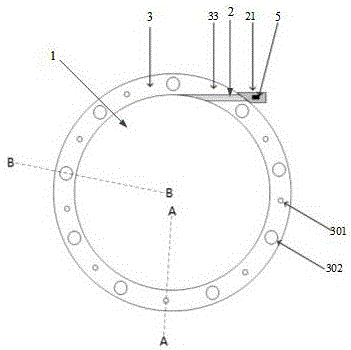
参阅图1,本发明实施例的GIS盆式绝缘子局部放电检测组件包括:盆式绝缘子本体1、传感光纤组件2和连接法兰3;其中,所述传感光纤组件2绕设在所述盆式绝缘子本体1的外翻沿11的外侧,并且,所述传感光纤组件2的第一端设置有光纤接头21,以与外部光纤耦合器连接;所述传感光纤组件2的第二端连接有光反射镜4,用以使外部光源发射的光线经传感光纤组件2传导至所述盆式绝缘子本体1表面时被反射至所述外部光纤耦合器中;所述连接法兰3设置在所述盆式绝缘子本体1的外翻沿11上,所述连接法兰3上设置有容置通道,用以将所述传感光纤组件2卡设在所述盆式绝缘子本体1的外翻沿11与所述连接法兰3之间,并且,所述连接法兰3的侧壁上开设有所述传感光纤组件2的进线通道33,所述光纤接头21伸出所述进线通道33。Referring to FIG. 1, the GIS basin-type insulator partial discharge detection assembly according to the embodiment of the present invention includes: a basin-
具体而言,盆式绝缘子本体1为现有技术中的任意一种盆式绝缘子,其通过连接法兰3与气体绝缘开关设备内的其他零部件相连接。Specifically, the pot-
传感光纤组件2绕设在盆式绝缘子本体1的外翻沿11的外侧,即绕设在盆式绝缘子本体1的外翻沿11远离盆式绝缘子本体1的弧形部12的一侧,使得传感光纤与盆式绝缘子本体1紧密接触,大大提高了超声波的传递与感知效率。The sensing
较具体的,所述传感光纤组件2为由一端连接有光反射镜4的光纤呈螺旋状绕设而成的光纤层。光纤可以为单模光纤或多模光纤。每层光纤之间通过超声耦合胶水粘合构成光纤层。光纤层的厚度可以根据实际情况确定,例如可以为5mm。本实施例中,光纤层可以设置在盆式绝缘子本体1的外翻沿11外侧的中部。More specifically, the
连接法兰3可拆卸的设置在盆式绝缘子本体1的外翻沿11上,其侧壁上上开设有贯通壁面的进线通道33,传感光纤组件2的光纤接头21可以伸出进线通道33,并与外部检测装置连接,以获取局部放电产生的超声信号。The connecting
连接法兰3上靠近盆式绝缘子本体1的一侧开设有传感光纤组件2的容置通道,传感光纤组件2一端的光反射镜4可以置于该容置通道中,以使外界光源发射的光线经传感光纤组件2传导至反射镜4表面时被反射回去,其中,外界光源可以为激光器,光反射镜4可以为法拉第旋转反射镜。容置通道的设置,以便于将连接法兰3、传感光纤组件2和盆式绝缘子组件进行融合安装。The side of the connecting
本实施例中,连接法兰3的设置,在GIS运行过程中可以有效的保护传感光纤组件2免受外界污秽的污染。In this embodiment, the arrangement of the connecting
传感光纤组件2与连接法兰3上的容置通道之间填充有半导电胶,有利于保护传感光纤组件2。半导电胶选用超声耦合胶水,具有高超声耦合系数,可排除传感光纤组件2中每层绕制光纤之间的气体,提高超声信号对光纤的相位调制作用。Semiconductive glue is filled between the sensing
连接法兰3上的光纤进线管道靠近端口的部位填充有密封胶,在保护传感光纤组件2的同时,有效避免了外界污秽通过进线通道33污染光纤层和盆式绝缘子本体1。The part of the optical fiber inlet pipe on the connecting
优选的,光纤接头21上设置有光纤保护套5,可以有效保护光纤接头21免受外界污秽的侵蚀。Preferably, the
上述显然可以得出,本实施例中提供的GIS盆式绝缘子局部放电检测组件,通过将传感光纤组件绕设在盆式绝缘子本体的外侧,使得局部放电缺陷产生的超声信号经盆式绝缘子本体作用于传感光纤组件上,充分减小了局放超声信号在气体中传播衰减对检测造成的不利影响,从而提高了盆式绝缘子表面金属微粒缺陷放电的检测精度;此外,通过在连接法兰上设置传感光纤组件的容置通道和进线通道,使得传感光纤组件能与盆式绝缘子本体表面紧密接触,大大提高了超声波的传递与感知效率,通过连接法兰形成金属屏蔽层,使得传感光纤组件所在位置的电场强度极低,进一步降低了外界对传感光纤组件的干扰。It can be clearly drawn from the above that the GIS basin insulator partial discharge detection assembly provided in this embodiment, by winding the sensing optical fiber assembly on the outside of the basin type insulator body, makes the ultrasonic signal generated by the partial discharge defect pass through the basin type insulator body. Acting on the sensing optical fiber assembly, the adverse effect of the partial discharge ultrasonic signal propagation attenuation in the gas on the detection is fully reduced, thereby improving the detection accuracy of the metal particle defect discharge on the surface of the basin insulator; The accommodating channel and the incoming line channel of the sensing optical fiber assembly are set on the upper part, so that the sensing optical fiber assembly can be in close contact with the surface of the basin insulator body, which greatly improves the transmission and sensing efficiency of ultrasonic waves. The metal shielding layer is formed through the connecting flange, so that the The electric field strength at the location where the sensing optical fiber assembly is located is extremely low, which further reduces external interference to the sensing optical fiber assembly.
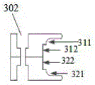
参阅图2至图4, 所述连接法兰3包括:相对接的第一法兰盘31和第二法兰盘32;其中,所述第一法兰盘31和所述第二法兰盘32分别设置在所述盆式绝缘子本体1的外翻沿11的上下两端;所述第一法兰盘31上自靠近所述盆式绝缘子本体1的外翻沿11的一侧向远离所述外翻沿11的一侧依次设置有第一环形卡槽311和第一环形凹槽312;所述第二法兰盘32上自靠近所述盆式绝缘子本体1的外翻沿11的一侧向远离所述外翻沿11的一侧依次设置有第二环形卡槽321和第二环形凹槽322;所述第一环形卡槽311和所述第二环形卡槽321相对接形成卡设部,用以卡接所述盆式绝缘子本体1的外翻沿11;所述第一环形凹槽312和所述第二环形凹槽322相对接形成所述传感光纤组件2的容置通道,所述容置通道与所述进线通道33连通。Referring to FIG. 2 to FIG. 4 , the connecting
具体而言,第一法兰盘31和第二法兰盘32的结构可以相同,二者对称设置在盆式绝缘子本体1的外翻沿11的上下两侧。Specifically, the structures of the first flange 31 and the
第一环形凹槽312与第二环形凹槽322对接后形成的卡设部的形状与盆式绝缘子本体1的外翻沿11的形状相适配。第一环形卡槽311与第二环形卡槽321呈凹台状结构,其深度可以小于等于盆式绝缘子本体1的外翻沿11的宽度,高度与盆式绝缘子本体1的外翻沿11的厚度一致,以稳固的卡设在盆式绝缘子上。第一环形卡槽311与第二环形卡槽321对称设置,以形成卡设盆式绝缘子边沿的卡设通道。第一环形卡槽311和第二环形卡槽321的底部均设置有倒角,以便于与盆式绝缘子本体1的外翻沿11进行装配。The shape of the clamping portion formed after the first annular groove 312 and the second
第一环形凹槽312与第二环形凹槽322对接后形成的容置通道的形状与传感光纤组件2的形状相适配,第一环形凹槽312与第二环形凹槽322的深度可以等于传感光纤组件2的厚度。第一环形凹槽312与第二环形凹槽322对称设置,形成传感光纤组件2的容置通道。The shape of the accommodating channel formed after the first annular groove 312 and the second
较具体的,所述第一环形卡槽311和所述第一环形凹槽312相连通形成第一阶梯结构;所述第一环形卡槽311和所述第一环形凹槽312相连通形成第二阶梯结构,所述第一阶梯结构与所述第二阶梯结构对称设置。即:在连接法兰3的内侧设置呈阶梯状布置的环形卡槽和环形凹槽,以实现连接法兰3、传感光纤组件2和盆式绝缘子本体1的融合安装。More specifically, the first
第一环形凹槽312和第二环形凹槽322均与进线通道33连通,以将光纤接头21引出连接法兰3外部。The first annular groove 312 and the second
结合体图1至图3,所述第一法兰盘31和所述第二法兰盘32的侧壁中分别设置一贯通壁面的弧形槽,两个所述弧形槽相配合,形成所述进线通道33。1 to 3, the side walls of the first flange 31 and the
具体而言,第一法兰盘31和第二法兰盘32中的弧形槽可以为半圆弧形槽,两个弧形槽可以沿径向贯通第一法兰盘31或第二法兰盘32的壁面,也可倾斜于径向贯通第一法兰盘31或第二法兰盘32的壁面,倾斜设置时,其与第一环形凹槽312或第二环形凹槽322相切连接,过渡平滑。两个半圆弧形槽对接,形成一圆形通道,以作为传感光纤组件2的进线通道33。第一环形凹槽312和第二环形凹槽322与该圆形通道连通,以实现传感光纤组件2的安装,连接法兰3的设置,使得传感光纤组件2与气体绝缘开关设备能够更加牢固的连接。Specifically, the arc-shaped grooves in the first flange 31 and the
继续参阅图1,本实施例中,所述第一法兰盘31和所述第二法兰盘32上一一对应设置有若干用以连接所述盆式绝缘子本体1与气体绝缘开关设备的第一连接孔301和若干用以实现所述第一法兰盘31和所述第二法兰盘32对接的第二连接孔302。Continuing to refer to FIG. 1 , in this embodiment, the first flange 31 and the
具体而言,第一连接孔301为带有螺纹的通孔,以与连接盆式绝缘子与气体绝缘设备的连接件的形状相适配。第二连接孔302呈台阶状,其靠近连接法兰3上端面处的口径大于靠近连接法兰3下端面处的口径,以通过螺栓实现第一法兰盘31和第二法兰盘32的连接,第一法兰盘31和第二法兰盘32采用金属材质制成,以形成屏蔽层,使得传感光纤组件2所在的位置具有极低的电场强度。第一连接孔301的孔径可以小于第二连接孔302靠近连接法兰3上端面处的口径。Specifically, the
各第一连接孔沿第一法兰盘31或所述第二法兰盘32的周向均匀分布,各第二连接孔沿第一法兰盘31或所述第二法兰盘32的周向均匀分布;各第一连接孔与各第二连接孔的中心点位于同一圈。The first connection holes are evenly distributed along the circumference of the first flange 31 or the
第一连接孔301和第二连接孔302沿所述第一法兰盘31或所述第二法兰盘32的周向相间设置,以通过连接法兰3实现了盆式绝缘子本体1与气体绝缘开关设备壳体内的其他零部件的紧固连接。The
各个第一连接孔301和各第二连接孔302均远离第一凹槽或第二凹槽设置,以避免相互干涉。Each of the first connection holes 301 and each of the second connection holes 302 are disposed away from the first groove or the second groove to avoid mutual interference.
本实施例的安装过程如下:将第一法兰盘31套于盆式绝缘子本体1上后,将光纤层引出的光纤接头21安置在该法兰盘上的弧形凹槽后再将第二法兰盘32对称安装于绝缘纸本体上,用螺丝在法兰固定用螺纹孔进行安装拧紧;法兰安装完成后在所述光纤进线通道33外侧用密封胶进行填充,最后制作光纤接头21保护套,用来保护光纤接头21,防止污秽对光纤接头21的侵蚀。The installation process of this embodiment is as follows: after the first flange 31 is sleeved on the
综上,本发明提供的GIS盆式绝缘子局部放电检测组件,通过将传感光纤组件绕设在盆式绝缘子本体的外侧,使得局部放电缺陷产生的超声信号经盆式绝缘子本体作用于传感光纤组件上,充分减小了局放超声信号在气体中传播衰减对检测造成的不利影响,从而提高了盆式绝缘子表面金属微粒缺陷放电的检测精度;此外,通过在连接法兰上设置传感光纤组件的容置通道和进线通道,使得传感光纤组件能与盆式绝缘子本体表面紧密接触,通过连接法兰形成金属屏蔽层,使得传感光纤组件所在位置的电场强度极低,进一步降低了外界对传感光纤组件的干扰。To sum up, in the GIS basin-type insulator partial discharge detection assembly provided by the present invention, the sensing optical fiber assembly is wound on the outside of the basin-type insulator body, so that the ultrasonic signal generated by the partial discharge defect acts on the sensing fiber through the basin-type insulator body. On the component, the adverse effect of the partial discharge ultrasonic signal propagation attenuation in the gas on the detection is fully reduced, thereby improving the detection accuracy of the metal particle defect discharge on the surface of the basin insulator; in addition, the sensing fiber is arranged on the connecting flange. The accommodating channel and the wire inlet channel of the component make the sensing fiber component closely contact with the surface of the basin-type insulator body, and the metal shielding layer is formed through the connecting flange, so that the electric field intensity at the location of the sensing fiber component is extremely low, which further reduces the External interference to the sensing fiber optic assembly.
参阅图5,本实施例还提供了一种了GIS盆式绝缘子局部放电检测系统,其特征在于,包括:控制装置(图中未示出)、光源6、参考光纤7、光纤耦合器8、光电探测器9和上述实施例中的GIS盆式绝缘子局部放电检测组件;其中,所述光纤耦合器8的输入端与所述光源6连接,用以将所述光源发出的光线分为两束;所述参考光纤7的第一端连接有一光反射镜4;所述光纤耦合器8的第一输出端与所述GIS盆式绝缘子局部放电检测组件中的传感光纤组件2的第二端和所述参考光纤7的第二端均电性连接,用以将两束所述光线传输至所述传感光纤组件2和所述参考光纤7中,并使两束所述光线返回所述光纤耦合器时产生光干涉信号;所述光电探测器9与所述光纤耦合器8的第二输出端连接,用以接收所述光干涉信号并根据所述光干涉信号确定两束光线的干涉光强度变化;所述控制装置与所述光源6、所述光纤耦合器8和所述光电探测器9均电性连接,用以控制所述光源发出光线,并控制所述光纤耦合器将所述光源发出的光线分为两束,以及控制所述光电探测器将两束所述光线产生的光干涉信号转化为电信号,电信号的大小取决于干涉光强度,并根据所述电信号的变化确定是否存在超声信号,从而判断出所述GIS盆式绝缘子表面是否存在局部放电。Referring to FIG. 5, this embodiment also provides a GIS basin insulator partial discharge detection system, which is characterized in that it includes: a control device (not shown in the figure), a light source 6, a reference fiber 7, a fiber coupler 8, The photodetector 9 and the GIS basin-type insulator partial discharge detection assembly in the above embodiment; wherein, the input end of the optical fiber coupler 8 is connected to the light source 6 to divide the light emitted by the light source into two bundles The first end of the reference fiber 7 is connected with a light reflection mirror 4; the first output end of the fiber coupler 8 is connected with the second end of the sensing fiber assembly 2 in the GIS basin-type insulator partial discharge detection assembly and the second end of the reference fiber 7 are electrically connected to transmit the two beams of the light to the sensing fiber assembly 2 and the reference fiber 7, and make the two beams return to the The optical interference signal is generated when the optical fiber coupler is used; the photodetector 9 is connected to the second output end of the optical fiber coupler 8 to receive the optical interference signal and determine the interference of the two beams of light according to the optical interference signal The light intensity changes; the control device is electrically connected to the light source 6, the optical fiber coupler 8 and the photodetector 9 to control the light source to emit light, and to control the optical fiber coupler to The light emitted by the light source is divided into two beams, and the photodetector is controlled to convert the optical interference signals generated by the two beams of light into electrical signals. The change determines whether there is an ultrasonic signal, so as to determine whether there is a partial discharge on the surface of the GIS basin insulator.
具体而言,光源6可以为激光器。激光器、光耦合器、连接有光反射镜4的参考光纤7、连接有光反射镜4的传感光纤组件2和光电探测器9组成了Michelson干涉结构,传感光纤组件2第一端的光反射镜4与参考光纤第一端的光反射镜4类型相同。传感光纤组件2第二端的光纤接头21与光纤耦合器连接,参考光纤的第二端也与光纤耦合器连接。本实施例中还可以包括:电信号检测装置10,其与光电探测器9连接,用以检测经光电探测器9输出的电信号的变化。其中,电信号检测装置10可以为示波器。Specifically, the light source 6 may be a laser. The laser, the optical coupler, the
参考光纤与传感光纤组件2中的光纤类型相同,例如传感光纤组件2中的传感光纤与参考光纤的折射率相同。所述半导电胶可起到保护光纤层的作用。所述超声耦合胶水具有高超声耦合系数,可排除绕制光纤之间的气体,提高超声信号对光纤的相位调制作用。The reference fiber is of the same type as the fiber in the
Michelson干涉结构中,经光纤耦合器分出的两束光线干涉后,干涉光信号的光强I与两束光的光强及相位差有关:In the Michelson interference structure, after the two beams of light separated by the fiber coupler interfere, the light intensity I of the interfering light signal is related to the light intensity and phase difference of the two beams:
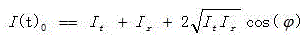
式中:I t为传感光纤中的光强,I r为参考光纤中的光强,φ为干涉光相位。In the formula: I t is the light intensity in the sensing fiber, I r is the light intensity in the reference fiber, and φ is the phase of the interference light.
若外部超声波对传感光纤发生作用,会引起传感光纤参数发生变化,导致传感光纤内光信号相位变化,则干涉光相位φ也会发生变化。其可以表示为:If the external ultrasonic wave acts on the sensing fiber, the parameters of the sensing fiber will change, resulting in a change in the phase of the optical signal in the sensing fiber, and the phase φ of the interference light will also change. It can be expressed as:

式中:φ 0干涉光相位常量。为由超声波引起的干涉光相位变化量。In the formula: φ 0 is the phase constant of the interference light. is the phase change of the interfering light caused by the ultrasonic wave.
将公式(2)代入(1)中,可得Substituting formula (2) into (1), we can get

干涉光信号由光电探测器进行光电转换后,输出的电信号U可以表示为After the interference light signal is photoelectrically converted by the photodetector, the output electrical signal U can be expressed as
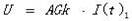
式中:k为光电探测器的光电转换系数,G为光电探测器增益系数,A为光电探测器的有效检测面积。where k is the photoelectric conversion coefficient of the photodetector, G is the gain coefficient of the photodetector, and A is the effective detection area of the photodetector.
进一步:further:

根据式(5)可知,由输出的电信号的变化即可得到干涉光强度变化,进而可以根据该干涉光强度变化判断是否存在局部放电缺陷。According to formula (5), it can be known that the change of the intensity of the interference light can be obtained from the change of the output electrical signal, and then it can be judged whether there is a partial discharge defect according to the change of the intensity of the interference light.
本实施例的工作原理为:光源发出的光被光纤耦合器分成两束光,两束光分别进入传感光纤和参考光纤中,两束光经反射镜反射后沿原光路返回,在耦合器处发生干涉,干涉信号经耦合器传输至光电探测器。光干涉信号的强度与两束光的相位差相关,当外部超声波作用于传感光纤上,传感光纤中光的相位受到调制,相应的传感光纤和参考光纤中的光信号相位差也会发生变化,并最终反映为探测器输出的电信号变化,通过控制装置分析输出的电信号变化变化情况即可获得超声信号,通过超声信号的有无即可判断盆式绝缘子本体表面是否存在局部放电缺陷。The working principle of this embodiment is as follows: the light emitted by the light source is divided into two beams of light by the optical fiber coupler. The two beams of light enter the sensing fiber and the reference fiber respectively. Interference occurs, and the interference signal is transmitted to the photodetector through the coupler. The intensity of the optical interference signal is related to the phase difference between the two beams of light. When an external ultrasonic wave acts on the sensing fiber, the phase of the light in the sensing fiber is modulated, and the phase difference between the corresponding optical signal in the sensing fiber and the reference fiber will also be The change occurs and is finally reflected as the change of the electrical signal output by the detector. The ultrasonic signal can be obtained by analyzing the change of the output electrical signal by the control device. Whether there is a partial discharge on the surface of the basin insulator body can be judged by the presence or absence of the ultrasonic signal. defect.
本实施例中,传感光纤组件的相关结构可参照上述实施例,此处不再赘述。In this embodiment, the related structure of the sensing optical fiber assembly can be referred to the above-mentioned embodiment, which will not be repeated here.
显然可以得出的是,本发明的GIS盆式绝缘子局部放电检测系统采用Michelson干涉结构去检测光纤层处是否有超声波的存在,进而判断出盆式绝缘子本体表面上是否有局部放电的缺陷,降低了局部放电超声信号在气体中传播的衰减程度,大大提高了局部放电缺陷的检测灵敏度。Obviously, it can be concluded that the GIS basin insulator partial discharge detection system of the present invention adopts the Michelson interference structure to detect whether there is an ultrasonic wave at the optical fiber layer, and then judges whether there is a partial discharge defect on the surface of the basin insulator body, reducing The attenuation degree of the partial discharge ultrasonic signal propagating in the gas is greatly improved, and the detection sensitivity of partial discharge defects is greatly improved.
显然,本领域的技术人员可以对本发明进行各种改动和变型而不脱离本发明的精神和范围。这样,倘若本发明的这些修改和变型属于本发明权利要求及其等同技术的范围之内,则本发明也意图包含这些改动和变型在内。It will be apparent to those skilled in the art that various modifications and variations can be made in the present invention without departing from the spirit and scope of the invention. Thus, provided that these modifications and variations of the present invention fall within the scope of the claims of the present invention and their equivalents, the present invention is also intended to include these modifications and variations.
Claims (9)
Priority Applications (1)
| Application Number | Priority Date | Filing Date | Title |
|---|---|---|---|
| CN202011029702.4A CN111929552B (en) | 2020-09-27 | 2020-09-27 | A GIS basin insulator partial discharge detection component and system |
Applications Claiming Priority (1)
| Application Number | Priority Date | Filing Date | Title |
|---|---|---|---|
| CN202011029702.4A CN111929552B (en) | 2020-09-27 | 2020-09-27 | A GIS basin insulator partial discharge detection component and system |
Publications (2)
| Publication Number | Publication Date |
|---|---|
| CN111929552A CN111929552A (en) | 2020-11-13 |
| CN111929552B true CN111929552B (en) | 2020-12-22 |
Family
ID=73333641
Family Applications (1)
| Application Number | Title | Priority Date | Filing Date |
|---|---|---|---|
| CN202011029702.4A Active CN111929552B (en) | 2020-09-27 | 2020-09-27 | A GIS basin insulator partial discharge detection component and system |
Country Status (1)
| Country | Link |
|---|---|
| CN (1) | CN111929552B (en) |
Families Citing this family (4)
| Publication number | Priority date | Publication date | Assignee | Title |
|---|---|---|---|---|
| CN114295970B (en) * | 2021-12-30 | 2024-05-28 | 四川艾德瑞电气有限公司 | High-altitude simulation test system of direct-current air circuit breaker |
| CN114609494A (en) * | 2022-05-12 | 2022-06-10 | 华北电力大学 | GIL partial discharge optical fiber sensing system |
| CN115343586A (en) * | 2022-08-26 | 2022-11-15 | 广东电网有限责任公司 | Ultrasonic detection device for partial discharge of transformer |
| CN115389883B (en) * | 2022-08-26 | 2026-02-06 | 广东电网有限责任公司 | Ultrasonic sensor and ultrasonic detection device |
Citations (6)
| Publication number | Priority date | Publication date | Assignee | Title |
|---|---|---|---|---|
| EP3029474A1 (en) * | 2014-11-19 | 2016-06-08 | AiQ Dienstleistungen UG (haftungsbeschränkt) | Fiber aligned and motionally coupled with electric cable |
| CN107327470A (en) * | 2017-06-01 | 2017-11-07 | 国网福建省电力有限公司泉州供电公司 | A kind of injecting glue bolt, disc insulator mounting structure and installation method |
| CN108594086A (en) * | 2018-04-13 | 2018-09-28 | 国网上海市电力公司 | All -fiber Michelson inside transformers shelf depreciation ultrasonic signal detecting system and method |
| CN109541413A (en) * | 2018-12-20 | 2019-03-29 | 国网上海市电力公司 | GIS partial discharge superfrequency, ultrasonic wave, light pulse combined detection system and method |
| CN109655724A (en) * | 2018-12-30 | 2019-04-19 | 国网辽宁省电力有限公司电力科学研究院 | Sensor for GIS device defects detection |
| CN111505468A (en) * | 2020-06-16 | 2020-08-07 | 华北电力大学 | Optical fiber distributed partial discharge detection system |
-
2020
- 2020-09-27 CN CN202011029702.4A patent/CN111929552B/en active Active
Patent Citations (6)
| Publication number | Priority date | Publication date | Assignee | Title |
|---|---|---|---|---|
| EP3029474A1 (en) * | 2014-11-19 | 2016-06-08 | AiQ Dienstleistungen UG (haftungsbeschränkt) | Fiber aligned and motionally coupled with electric cable |
| CN107327470A (en) * | 2017-06-01 | 2017-11-07 | 国网福建省电力有限公司泉州供电公司 | A kind of injecting glue bolt, disc insulator mounting structure and installation method |
| CN108594086A (en) * | 2018-04-13 | 2018-09-28 | 国网上海市电力公司 | All -fiber Michelson inside transformers shelf depreciation ultrasonic signal detecting system and method |
| CN109541413A (en) * | 2018-12-20 | 2019-03-29 | 国网上海市电力公司 | GIS partial discharge superfrequency, ultrasonic wave, light pulse combined detection system and method |
| CN109655724A (en) * | 2018-12-30 | 2019-04-19 | 国网辽宁省电力有限公司电力科学研究院 | Sensor for GIS device defects detection |
| CN111505468A (en) * | 2020-06-16 | 2020-08-07 | 华北电力大学 | Optical fiber distributed partial discharge detection system |
Non-Patent Citations (1)
| Title |
|---|
| 基于Michelson光纤干涉的GIS局部放电超声信号检测技术;周宏扬 等;《中国电机工程学报》;20191105;第39卷(第21期);6452-6459 * |
Also Published As
| Publication number | Publication date |
|---|---|
| CN111929552A (en) | 2020-11-13 |
Similar Documents
| Publication | Publication Date | Title |
|---|---|---|
| CN111929552B (en) | A GIS basin insulator partial discharge detection component and system | |
| CN1179205C (en) | Apparatus and method for monitoring a structure using a counter-propagating signal method for locating events | |
| CN115144712B (en) | Partial discharge optical ultrasonic detection system | |
| CN109709461B (en) | Partial discharge detection system | |
| CN113447774B (en) | Cable partial discharge detection sensor, system and method | |
| CN110208668B (en) | Optical fiber acoustic emission vibration sensor and partial discharge sensing system | |
| CN109786272B (en) | New IGBT packaging structure and packaging method with internal temperature measurement function | |
| CN116972343B (en) | Optical fiber sensing system suitable for pipeline leakage monitoring | |
| CN109669110A (en) | Sound focusing sensor and PD On-Line Measurement System and its detection method for shelf depreciation on-line checking | |
| CN111537848A (en) | Optical fiber detection method and device for partial discharge in GIS | |
| CN115421011A (en) | Ultrasonic-ultrahigh frequency cooperative detection device for partial discharge of transformer | |
| CN114167243A (en) | Optical fiber partial discharge monitoring system for transformer bushing | |
| CN108489597A (en) | A kind of acoustic detector and method based on hollow-core photonic crystal fiber | |
| CN210347841U (en) | A partial discharge localization device based on fluorescent fiber | |
| CN119413268B (en) | Built-in sound field measurement device for high-voltage electrical equipment and space optimization layout method | |
| CN113899995A (en) | Partial discharge detection method and device based on distributed feedback fiber laser | |
| CN218848268U (en) | Transformer bushing multi-array element optical fiber micro-water and ultrasonic partial discharge joint detection system | |
| CN118191530A (en) | EFPI sensor with acoustic directivity control function | |
| CN219456375U (en) | A kind of cable defect detection equipment | |
| CN210038030U (en) | Partial discharge detection system | |
| CN210038031U (en) | Single-core cable partial discharge sensor and partial discharge sensor array | |
| CN116222740A (en) | Compensation interferometer structure for optical fiber hydrophone | |
| CN111219602B (en) | Sensor devices for gas leak detection | |
| CN208188246U (en) | A kind of fault detection system of distribution overhead line | |
| JPH02181668A (en) | Abnormality detecting device for gas insulation electric equipment |
Legal Events
| Date | Code | Title | Description |
|---|---|---|---|
| PB01 | Publication | ||
| PB01 | Publication | ||
| SE01 | Entry into force of request for substantive examination | ||
| SE01 | Entry into force of request for substantive examination | ||
| GR01 | Patent grant | ||
| GR01 | Patent grant |