CN111927517A - Automatic take mining equipment of supporting - Google Patents
Automatic take mining equipment of supporting Download PDFInfo
- Publication number
- CN111927517A CN111927517A CN202010805760.5A CN202010805760A CN111927517A CN 111927517 A CN111927517 A CN 111927517A CN 202010805760 A CN202010805760 A CN 202010805760A CN 111927517 A CN111927517 A CN 111927517A
- Authority
- CN
- China
- Prior art keywords
- cavity
- fixedly connected
- lifting
- spring
- gear
- Prior art date
- Legal status (The legal status is an assumption and is not a legal conclusion. Google has not performed a legal analysis and makes no representation as to the accuracy of the status listed.)
- Withdrawn
Links
Images


Classifications
-
- E—FIXED CONSTRUCTIONS
- E21—EARTH DRILLING; MINING
- E21D—SHAFTS; TUNNELS; GALLERIES; LARGE UNDERGROUND CHAMBERS
- E21D23/00—Mine roof supports for step- by- step movement, e.g. in combination with provisions for shifting of conveyors, mining machines, or guides therefor
- E21D23/04—Structural features of the supporting construction, e.g. linking members between adjacent frames or sets of props; Means for counteracting lateral sliding on inclined floor
-
- E—FIXED CONSTRUCTIONS
- E21—EARTH DRILLING; MINING
- E21C—MINING OR QUARRYING
- E21C29/00—Propulsion of machines for slitting or completely freeing the mineral from the seam
- E21C29/22—Propulsion of machines for slitting or completely freeing the mineral from the seam by wheels, endless tracks or the like
-
- E—FIXED CONSTRUCTIONS
- E21—EARTH DRILLING; MINING
- E21D—SHAFTS; TUNNELS; GALLERIES; LARGE UNDERGROUND CHAMBERS
- E21D23/00—Mine roof supports for step- by- step movement, e.g. in combination with provisions for shifting of conveyors, mining machines, or guides therefor
- E21D23/08—Advancing mechanisms
- E21D23/10—Advancing mechanisms with advancing devices separate from the supporting construction
-
- E—FIXED CONSTRUCTIONS
- E21—EARTH DRILLING; MINING
- E21D—SHAFTS; TUNNELS; GALLERIES; LARGE UNDERGROUND CHAMBERS
- E21D23/00—Mine roof supports for step- by- step movement, e.g. in combination with provisions for shifting of conveyors, mining machines, or guides therefor
- E21D23/16—Hydraulic or pneumatic features, e.g. circuits, arrangement or adaptation of valves, setting or retracting devices
- E21D23/26—Hydraulic or pneumatic control
Abstract
The invention discloses mining equipment capable of automatically supporting, which comprises a mining machine shell, wherein a transmission cavity is arranged in the mining machine shell, a driven cavity is arranged above the transmission cavity, a transmission mechanism is arranged in the transmission cavity, a driven mechanism is arranged in the driven cavity, a pushing mechanism is arranged above the driven mechanism, a driving mechanism is arranged below the transmission cavity, a lifting mechanism is arranged on the left side of the pushing mechanism, a push-out mechanism is arranged in the front and the rear of the mining machine shell, an oil cavity mechanism is arranged below the lifting mechanism, the device has simple structure and simple and convenient operation, the device does not need artificial operation to build a support when in use, the mining machine can build a support when the mining machine goes forward, the support can be built once every time the mining machine goes forward for a certain distance, the support structure built by the hydraulic column and the support plate is firm, the safety performance is very high, and workers are not needed to be on the side, so that potential safety hazards generated during mine hole operation are greatly reduced.
Description
Technical Field
The invention relates to the field of mining equipment, in particular to mining equipment capable of automatically supporting.
Background
When mining operation is carried out in a mine hole, in order to further reduce disasters such as collapse, supports are often required to be built, the traditional support building is that a mining machine works in the front, and the artificial support building is carried out behind the mining machine.
Disclosure of Invention
The invention aims to solve the technical problem of providing mining equipment with automatic support construction, and solves the problems that the support construction needs manual operation in the mining process.
The invention is realized by the following technical scheme.
The invention relates to automatic shoring mining equipment, which comprises a mining machine shell, wherein a transmission cavity is arranged in the mining machine shell, a driven cavity is arranged above the transmission cavity, a transmission mechanism is arranged in the transmission cavity, a driven mechanism is arranged in the driven cavity, a pushing mechanism is arranged above the driven mechanism, a driving mechanism is arranged below the transmission cavity, a lifting mechanism is arranged on the left side of the pushing mechanism, a pushing mechanism is arranged in the front and back of the mining machine shell, an oil cavity mechanism is arranged below the lifting mechanism, the lifting mechanism comprises a lifting cavity, a lifting platform which is connected to the left inner wall and the right inner wall of the lifting cavity in a sliding manner is arranged in the lifting cavity, a first telescopic cavity is arranged in the lifting platform, a lifting plate is arranged in the first telescopic cavity, a lifting rod is fixedly connected to the lower end of the lifting plate, and a, the lower end of the lifting plate is fixedly connected with a first spring, the first spring is fixedly connected with the lower inner wall of the lifting cavity, the lower end of the first piston is provided with a first pneumatic cavity, the shell of the mining machine is provided with a first moving cavity with a left opening, the first moving cavity is connected with the first pneumatic cavity, a first trapezoidal block is arranged in the first moving cavity, the right end of the first trapezoidal block is fixedly connected with a second spring, the second spring is fixedly connected with the right inner wall of the first moving cavity, the first moving cavity is also internally provided with a first push plate, the left end of the first push plate is fixedly connected with a push rod, the push rod penetrates through the left end of the shell of the mining machine and is fixedly connected with a second piston, the second piston moves leftwards and rightwards in the first pneumatic cavity, the lower end of the lifting table is fixedly connected with a third spring and a first pull rope, and the third spring is fixedly connected with the lower, the lower end of the lifting cavity is provided with a second air pressure cavity, a third piston is arranged in the second air pressure cavity, and the third piston is fixedly connected with the first pull rope.
Further, the ejecting mechanism comprises a second moving cavity, a pushing block is connected to the second moving cavity in a sliding mode, a third moving cavity is arranged in the pushing block, a second trapezoidal block is arranged in the third moving cavity, a fourth spring and a second pull rope are fixedly connected to the upper end of the second trapezoidal block, a fourth piston is fixedly connected to the upper end of the second pull rope and is arranged on the second pneumatic cavity in a reciprocating mode, a fifth spring is fixedly connected to the right end of the pushing block and fixedly connected with the right inner wall of the second moving cavity, an oil pipe capable of stretching is further connected to the right end of the pushing block, two baffles are fixedly connected to the left end of the pushing block, a stop block is hinged to the baffles, a torsion spring is arranged at the joint of the stop block and the baffles, an oil injection port is formed in the left end face of the pushing block, and a hydraulic column is placed between the baffle and the stop block.
Further, the transmission mechanism comprises a first transmission shaft rotationally connected to the front inner wall and the rear inner wall of the transmission cavity, a motor is in power connection with the first transmission shaft, a first gear and a second gear are fixedly connected to the first transmission shaft, a second transmission shaft and a third transmission shaft are rotationally connected to the upper portion of the first transmission shaft, a third gear is in spline connection with the second transmission shaft, a first annular moving cavity is arranged in the third gear, a first blocking piece is arranged in the first annular moving cavity, a fourth pull rope is fixedly connected to the left end of the first blocking piece, a fifth piston is fixedly connected to the left end of the fourth pull rope, the fifth piston moves left and right in a second air pressure cavity, a sixth spring is fixedly connected to the left end face of the third gear, the sixth spring is fixedly connected to the front inner wall of the transmission cavity, and a fourth gear is in spline connection with the third transmission shaft, fixedly connected with first line wheel and second line wheel on the third transmission shaft, it has the seventh stay cord to wind on the first line wheel, the seventh stay cord run through the mining machine shell with the elevating platform is connected, it has the third stay cord to wind on the second line wheel, the third stay cord runs through the mining machine shell and is connected with the ejector pad, be equipped with the second annular in the fourth gear and remove the chamber, the annular removes the intracavity and is equipped with the second separation blade, second separation blade fixedly connected with fifth stay cord, fixedly connected with seventh spring on the fourth gear, seventh spring fixed connection be in on the transmission chamber rear inner wall, third gear and first gear engagement.
Furthermore, the driven mechanism comprises a first driven shaft which is rotatably connected to the front inner wall and the rear inner wall of the driven cavity, a first bevel gear, a fifth gear and a first belt pulley are fixedly connected to the first driven shaft, and a belt is wound on the first belt pulley.
Further, the pushing mechanism comprises a fixing plate fixedly connected to the upper right end of the shell of the mining machine, an eighth spring is fixedly connected to the left end of the fixing plate, a second push plate is fixedly connected to the left end of the eighth spring, a cam is arranged at the right end of the second push plate, a second driven shaft is fixedly connected to the cam, the second driven shaft is rotatably connected to the shell of the mining machine, a third bevel gear is fixedly connected to the second driven shaft, a third driven shaft is rotatably connected to the left inner wall of the driven cavity, a fourth bevel gear, a second bevel gear and an incomplete gear are fixedly connected to the third driven shaft, the fourth bevel gear is meshed with the third bevel gear, the first bevel gear is meshed with the second bevel gear, a lifting groove is arranged on the left side of the driven cavity, a lifting block is arranged in the lifting groove, and a storage groove is arranged on the left side, the storage tank is internally provided with a supporting plate, and the right lower part of the storage tank is provided with an outlet.
Further, connect the parcel to have the track, wheel fixedly connected with fourth driven shaft, fixedly connected with second band pulley on the fourth driven shaft, around having the belt on the second band pulley, fixedly connected with third band pulley on the fourth driven shaft front and back end, the third band pulley is external to have the conveyer belt.
Further, the oil cavity mechanism comprises a large oil cavity, the lower end of the large oil cavity is connected with an oil outlet pipe, a sensing valve is arranged in the oil outlet pipe, a small oil cavity is arranged at the lower end of the oil outlet pipe, an upper sensing switch and a lower sensing switch are arranged in the small oil cavity, a pressing plate is further arranged in the small oil cavity, a ninth spring and a fifth pull rope are fixedly connected to the lower end of the pressing plate, and the small oil cavity is connected with the oil pipe.
The invention has the beneficial effects that: the device simple structure, it is easy and simple to handle, the device does not need artificial operation to build when using and struts, and the mining machine exploitation gos forward, and one time can be built to strut for one section distance every marching, and the supporting construction through hydraulic pressure post and backup pad constitution is firm, and the security performance is very high to do not need worker people on the edge, produced potential safety hazard when having significantly reduced the operation of ore hole.
Drawings
In order to more clearly illustrate the embodiments of the invention or the technical solutions in the prior art, the drawings used in the description of the embodiments or the prior art will be briefly described below, and it is obvious that the drawings in the following description are only some embodiments of the invention, and it is obvious for those skilled in the art that other drawings can be obtained based on these drawings without creative efforts.
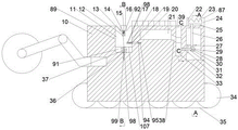
FIG. 1 is an internal structure of an embodiment of the present invention;
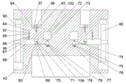
FIG. 2 is a schematic cross-sectional view taken along line A-A of FIG. 1 according to an embodiment of the present invention;
FIG. 3 is a schematic cross-sectional view of the structure of section B-B in FIG. 1 according to an embodiment of the present invention;
FIG. 4 is a schematic cross-sectional view of the structure of section C-C in FIG. 1 according to an embodiment of the present invention;
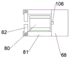
FIG. 5 is a schematic top view of the ejection mechanism of FIG. 3 according to an embodiment of the present invention;
Detailed Description
The invention will now be described in detail with reference to fig. 1-5, wherein for ease of description the orientations described hereinafter are now defined as follows: the up, down, left, right, and front-back directions described below correspond to the up, down, left, right, and front-back directions in the projection relationship of fig. 1 itself.
With reference to fig. 1-5, the mining equipment with automatic supporting function comprises a mining machine shell 10, a transmission cavity 83 is arranged in the mining machine shell 10, a driven cavity 84 is arranged above the transmission cavity 83, a transmission mechanism 85 is arranged in the transmission cavity 83, a driven mechanism 86 is arranged in the driven cavity 84, a pushing mechanism 87 is arranged above the driven mechanism 86, a driving mechanism 88 is arranged below the transmission cavity 83, a lifting mechanism 89 is arranged on the left side of the pushing mechanism 87, a pushing mechanism 90 is arranged in the front and back of the mining machine shell 10, an oil cavity mechanism 102 is arranged below the lifting mechanism 89, the lifting mechanism 89 comprises a lifting cavity 91, a lifting table 11 which is slidably connected to the left inner wall and the right inner wall of the lifting cavity 91 is arranged in the lifting cavity 91, a first telescopic cavity 92 is arranged in the lifting table 11, and a lifting plate 14 is arranged in the first telescopic cavity 92, the lower end of the lifting plate 14 is fixedly connected with a lifting rod 13, the lower end of the lifting rod 13 is fixedly connected with a first piston 12, the lower end of the lifting plate 14 is fixedly connected with one end of a first spring 15, the other end of the first spring 15 is fixedly connected with the lower inner wall of the lifting cavity 91, the lower end of the first piston 12 is provided with a first air pressure cavity 98, the mining machine shell 10 is provided with a first moving cavity 94 with a leftward opening, the first moving cavity 91 is connected with the first air pressure cavity 98, a first trapezoidal block 20 is arranged in the first moving cavity 94, the right end of the first trapezoidal block 20 is fixedly connected with a second spring 95, the second spring 95 is fixedly connected with the right inner wall of the first moving cavity 94, a first push plate 19 is further arranged in the first moving cavity 94, the left end of the first push plate 19 is fixedly connected with a push rod 18, the push rod 18 penetrates through the left end of the mining machine shell 10 and is fixedly connected with a, the second piston 17 moves left and right in the first pneumatic cavity 98, the lower end of the lifting platform 11 is fixedly connected with a third spring 37 and a first pull rope 36, the third spring 37 is fixedly connected to the lower inner wall of the lifting cavity 91, the lower end of the lifting cavity 91 is provided with a second pneumatic cavity 64, a third piston 99 is arranged in the second pneumatic cavity 64, and the third piston 99 is fixedly connected with the first pull rope 36.
Beneficially, the push-out mechanism 90 includes a second moving cavity 93, a push block 68 is slidably connected in the second moving cavity 93, a third moving cavity 96 is arranged in the push block 68, a second trapezoidal block 67 is arranged in the third moving cavity 96, a fourth spring 66 and a second pull rope 65 are fixedly connected to the upper end of the second trapezoidal block 67, a fourth piston 97 is fixedly connected to the upper end of the second pull rope 65, the fourth piston 97 moves up and down in the second pneumatic cavity 64, a fifth spring 70 is fixedly connected to the right end of the push block 68, the fifth spring 70 is fixedly connected to the right inner wall of the second moving cavity 93, a telescopic oil pipe 69 is further connected to the right end of the push block 68, two baffle plates 81 are fixedly connected to the left end of the push block 69, a stopper 82 is hinged to the baffle plate 81, a torsion spring is arranged at the connection between the baffle plate 82 and the baffle plate 81, an oil injection port 106 is arranged on the left end surface of the push block, a hydraulic cylinder 80 is placed between the baffle 82 and the stop 81.
Advantageously, the transmission mechanism 85 comprises a first transmission shaft 46 rotatably connected to the front and rear inner walls of the transmission chamber 83, a motor 48 is rotatably connected to the first transmission shaft 46, a first gear 49 and a second gear 47 are fixedly connected to the first transmission shaft 46, a second transmission shaft 58 and a third transmission shaft 50 are rotatably connected to the upper side of the first transmission shaft 46, a third gear 60 is splined to the second transmission shaft 58, a first annular moving chamber 52 is arranged in the third gear 60, a first baffle 61 is arranged in the first annular moving chamber 52, a fourth pull rope 57 is fixedly connected to the left end of the first baffle 61, a fifth piston 56 is fixedly connected to the left end of the fourth pull rope 57, the fifth piston 56 moves left and right in the second pneumatic chamber 64, a sixth spring 59 is fixedly connected to the left end surface of the third gear 60, and the sixth spring 59 is fixedly connected to the front inner wall of the transmission chamber 83, a fourth gear 53 is connected to the third transmission shaft 50 through a spline, a first wire wheel 54 and a second wire wheel 55 are fixedly connected to the third transmission shaft 50, a seventh pull rope 107 is wound on the first wire wheel 54, the seventh pull rope 107 penetrates through the outer shell 10 of the mining machine and is connected with the lifting platform 11, a third pull rope 71 is wound on the second wire wheel 55, the third pull rope 71 penetrates through the outer shell 10 of the mining machine and is connected with the push block 68, a second annular moving cavity 100 is arranged in the fourth gear 53, a second baffle 101 is arranged in the annular moving cavity, a fifth pull rope 77 is fixedly connected to the second baffle 101, a seventh spring 51 is fixedly connected to the fourth gear 53, the seventh spring 57 is fixedly connected to the rear inner wall of the transmission cavity 83, and the third gear 60 is meshed with the first gear 49.
Advantageously, the driven mechanism 86 comprises a first driven shaft 29 rotatably connected to the front and rear inner walls of the driven chamber 84, the first driven shaft 29 is fixedly connected with a first bevel gear 28, a fifth gear 40 and a first belt pulley 41, and the first belt pulley 41 is wound with a belt 42.
Advantageously, the pushing mechanism 87 comprises a fixing plate 24 fixedly connected to the upper right end of the mining machine housing 10, an eighth spring 23 is fixedly connected to the left end of the fixing plate 24, a second push plate 22 is fixedly connected to the left end of the eighth spring 23, a cam 25 is arranged at the right end of the second push plate 22, a second driven shaft 26 is fixedly connected to the cam 25, the second driven shaft 26 is rotatably connected to the mining machine housing 10, a third bevel gear 27 is fixedly connected to the second driven shaft 26, a third driven shaft 30 is rotatably connected to the left inner wall of the driven cavity 84, a fourth bevel gear 32, a second bevel gear 31 and a incomplete gear 62 are fixedly connected to the third driven shaft 30, the fourth bevel gear 32 is engaged with the third bevel gear 27, the first bevel gear 28 is engaged with the second bevel gear 31, a lifting groove 39 is arranged at the left side of the driven cavity 84, the lifting groove 39 is internally provided with a lifting block 33, the left side of the lifting groove 39 is provided with a storage groove 21, the storage groove 21 is internally provided with a support plate 16, and the lower right of the storage groove 21 is provided with an outlet 38.
Advantageously, the belt is wrapped by a track 35, the wheel 34 is fixedly connected with a fourth driven shaft 43, the fourth driven shaft 43 is fixedly connected with a second belt wheel 44, the second belt wheel is wound by a belt 42, the front end and the rear end of the fourth driven shaft 43 are fixedly connected with a third belt wheel 105, and the third belt wheel 105 is externally connected with a conveying belt 103.
Beneficially, the oil chamber mechanism 102 includes a large oil chamber 72, an oil outlet pipe 73 is connected to the lower end of the large oil chamber 72, an induction valve 74 is arranged in the oil outlet pipe 73, a small oil chamber 104 is arranged at the lower end of the oil outlet pipe 73, an upper induction switch 79 and a lower induction switch 78 are arranged in the small oil chamber 104, a pressure plate 75 is further arranged in the small oil chamber 104, a ninth spring 76 and a fifth pull rope 77 are fixedly connected to the lower end of the pressure plate 75, and the small oil chamber 104 is connected to the oil pipe 69.
Sequence of mechanical actions of the whole device:
1: activating motor 48 to rotate first drive shaft 46, thereby rotating first gear 49 and second gear 47, thereby rotating third gear 60, thereby rotating fifth gear 40, thereby rotating first driven shaft 29, thereby rotating first pulley 41 and first bevel gear 28, thereby rotating second pulley 44, thereby rotating fourth driven shaft 43, thereby rotating wheels 34 and third pulley 105, thereby rotating belt 103 to move hydraulic cylinder 80, thereby rotating crawler 35 to advance the mining machine;
2: the first bevel gear 28 drives the second bevel gear 31 to rotate, so as to drive the third driven shaft 30 to rotate, so as to drive the incomplete gear 62 to rotate, so that the lifting block 33 performs reciprocating motion of moving up and down, so that the support plate 16 is lifted from the storage groove 21, the third driven shaft 30 drives the fourth bevel gear 32 to rotate, so as to drive the third bevel gear 27 to rotate, so as to drive the second driven shaft 26 to rotate, so as to drive the cam 25 to rotate, and the second push plate 22 performs reciprocating motion of moving left and right under the action of the cam 25 and the eighth spring 23, so that the support plate falls into the lifting mechanism 89;
3: the support plate 16 falls into the elevator platform 11, causing the elevator plate 14 to descend, thereby causing the elevator rod 13 to descend, thereby causing the first piston 12 to descend, thereby causing the second piston 17 to move to the right, thereby causing the push rod 18 to move to the right, thereby causing the first push plate 19 to move to the right, thereby causing the first trapezoidal block 20 to move to the right, causing the elevator platform 11 to contact the restriction, causing the compressed third spring 37 to spring open, thereby causing the elevator platform 11 to rise against the roof of the mine;
4: after the lifting platform 11 is lifted, the first pull rope 36 is driven to lift, so that the third piston 99 is driven to lift, so that the fourth piston 97 is driven to lift, the fifth piston 56 is driven to move leftwards, the first blocking piece 61 is driven to move leftwards, so that the third gear 60 is driven to be disengaged, so that the pushing mechanism 87 and the driving mechanism 88 stop working, the fourth piston 97 is lifted to drive the second trapezoidal block 67 to lift, so that the pushing block 68 is separated from limitation, so that the pushing block 68 pushes out the hydraulic column 80, and the two blocking plates 81 and the blocking blocks 82 are arranged around the hydraulic column 80, so that the hydraulic column 80 can be pushed out stably, the oil filling port 106 injects hydraulic oil into the hydraulic column 80 after being pushed out, so that the hydraulic column 80 is lifted to prop the supporting plate 16 tightly, after the oil injection of the small oil chamber 104 is finished, the pressure plate 75 is lifted under the action of the ninth spring 76, so that the fifth pull rope 77 is pulled, so that the fourth gear 53 is driven to move rightwards, so, the third transmission shaft 50 is driven to rotate, so that the first wire wheel 54 and the second wire wheel 55 are driven to rotate, the third pull rope 71 and the seventh pull rope 107 are tensioned, the lifting platform 11 and the push block 68 are reset, the pressure plate 75 in the small oil cavity 104 is lifted and touches the upper inductive switch 79, so that the inductive valve 74 is opened to supplement hydraulic oil, the pressure plate 75 is lowered and touches the lower inductive switch 78 by the weight of the hydraulic oil, so that the inductive valve 74 is closed, and the effect of supporting while advancing is achieved in a circulating manner;
the above embodiments are merely illustrative of the technical ideas and features of the present invention, and the purpose thereof is to enable those skilled in the art to understand the contents of the present invention and implement the present invention, and not to limit the protection scope of the present invention. All equivalent changes and modifications made according to the spirit of the present invention should be covered within the protection scope of the present invention.
Claims (7)
1. An automatic lap mining equipment of supporting, includes the mining machine shell, its characterized in that: a transmission cavity is arranged in the mining machine shell, a driven cavity is arranged above the transmission cavity, a transmission mechanism is arranged in the transmission cavity, a driven mechanism is arranged in the driven cavity, a pushing mechanism is arranged above the driven mechanism, a driving mechanism is arranged below the transmission cavity, a lifting mechanism is arranged on the left side of the pushing mechanism, a pushing mechanism is arranged in the front and rear of the mining machine shell, an oil cavity mechanism is arranged below the lifting mechanism, the lifting mechanism comprises a lifting cavity, a lifting table which is connected to the left inner wall and the right inner wall of the lifting cavity in a sliding manner is arranged in the lifting cavity, a first telescopic cavity is arranged in the lifting table, a lifting plate is arranged in the first telescopic cavity, a lifting rod is fixedly connected to the lower end of the lifting plate, a first piston is fixedly connected to the lower end of the lifting rod, a first spring is fixedly connected to the lower end of the, the lower end of the first piston is provided with a first pneumatic cavity, the shell of the mining machine is provided with a first moving cavity with a left opening, the first moving cavity is connected with the first pneumatic cavity, a first trapezoid block is arranged in the first moving cavity, the right end of the first trapezoid block is fixedly connected with a second spring, the second spring is fixedly connected with the right inner wall of the first moving cavity, a first push plate is further arranged in the first moving cavity, the left end of the first push plate is fixedly connected with a push rod, the push rod penetrates through the left end of the shell of the mining machine and is fixedly connected with a second piston, the second piston moves left and right in the first pneumatic cavity, the lower end of the lifting table is fixedly connected with a third spring and a first pull rope, the third spring is fixedly connected on the lower inner wall of the lifting cavity, the lower end of the lifting cavity is provided with a second pneumatic cavity, and a third piston is arranged in the second pneumatic, the third piston is fixedly connected with the first pull rope.
2. An automatically timbering mining apparatus as claimed in claim 1, characterised in that: the pushing mechanism comprises a second moving cavity, a pushing block is connected to the second moving cavity in a sliding mode, a third moving cavity is arranged in the pushing block, a second trapezoidal block is arranged in the third moving cavity, a fourth spring and a second pull rope are fixedly connected to the upper end of the second trapezoidal block, a fourth piston is fixedly connected to the upper end of the second pull rope and is arranged on the second air pressure cavity in a vertical moving mode, a fifth spring is fixedly connected to the right end of the pushing block and fixedly connected with the right inner wall of the second moving cavity, a telescopic oil pipe is further connected to the right end of the pushing block, two baffles are fixedly connected to the left end of the pushing block, a baffle block is hinged to each baffle, a torsion spring is arranged at the joint of the baffle block and the baffle, an oil injection port is formed in the left end face of the pushing block, and a hydraulic column is placed between the baffle and the baffle.
3. An automatically timbering mining apparatus as claimed in claim 1, characterised in that: the transmission mechanism comprises a first transmission shaft which is rotationally connected to the front inner wall and the rear inner wall of a transmission cavity, a motor is in power connection with the first transmission shaft, a first gear and a second gear are fixedly connected to the first transmission shaft, a second transmission shaft and a third transmission shaft are rotationally connected above the first transmission shaft, a third gear is in spline connection with the second transmission shaft, a first annular moving cavity is arranged in the third gear, a first blocking piece is arranged in the first annular moving cavity, a fourth pull rope is fixedly connected to the left end of the first blocking piece, a fifth piston is fixedly connected to the left end of the fourth pull rope, the fifth piston moves left and right in a second air pressure cavity, a sixth spring is fixedly connected to the left end face of the third gear, the sixth spring is fixedly connected to the front inner wall of the transmission cavity, a fourth gear is in spline connection with the third transmission shaft, and a first wire wheel and a second wire wheel are fixedly connected to the third transmission shaft, the novel mining machine is characterized in that a seventh pull rope is wound on the first wire wheel, the seventh pull rope penetrates through the shell of the mining machine and is connected with the lifting platform, a third pull rope is wound on the second wire wheel, the third pull rope penetrates through the shell of the mining machine and is connected with the push block, a second annular moving cavity is arranged in the fourth gear, a second blocking piece is arranged in the annular moving cavity, the second blocking piece is fixedly connected with a fifth pull rope, a seventh spring is fixedly connected to the fourth gear, the seventh spring is fixedly connected to the rear inner wall of the transmission cavity, and the third gear is meshed with the first gear.
4. An automatically timbering mining apparatus as claimed in claim 1, characterised in that: the driven mechanism comprises a first driven shaft which is rotatably connected to the front inner wall and the rear inner wall of the driven cavity, a first bevel gear, a fifth gear and a first belt wheel are fixedly connected to the first driven shaft, and a belt is wound on the first belt wheel.
5. An automatically timbering mining apparatus as claimed in claim 1, characterised in that: the pushing mechanism comprises a fixing plate fixedly connected to the upper right end of the shell of the mining machine, an eighth spring is fixedly connected to the left end of the fixing plate, a second push plate is fixedly connected to the left end of the eighth spring, a cam is arranged at the right end of the second push plate, a second driven shaft is fixedly connected to the cam, the second driven shaft is rotatably connected to the shell of the mining machine, a third bevel gear is fixedly connected to the second driven shaft, a third driven shaft is rotatably connected to the left inner wall of the driven cavity, a fourth bevel gear, a second bevel gear and an incomplete gear are fixedly connected to the third driven shaft, the fourth bevel gear is meshed with the third bevel gear, the first bevel gear is meshed with the second bevel gear, a lifting groove is arranged on the left side of the driven cavity, a lifting block is arranged in the lifting groove, a storage groove is arranged on the left side of the lifting groove, and a, an outlet is arranged at the lower right part of the storage groove.
6. An automatically timbering mining apparatus as claimed in claim 1, characterised in that: the wheel is fixedly connected with a fourth driven shaft, a second belt wheel is fixedly connected to the fourth driven shaft, a belt is wound on the second belt wheel, a third belt wheel is fixedly connected to the front end and the rear end of the fourth driven shaft, and a conveying belt is connected to the third belt wheel externally.
7. An automatically timbering mining apparatus as claimed in claim 1, characterised in that: the oil cavity mechanism comprises a large oil cavity, the lower end of the large oil cavity is connected with an oil outlet pipe, a sensing valve is arranged in the oil outlet pipe, a small oil cavity is arranged at the lower end of the oil outlet pipe, an upper sensing switch and a lower sensing switch are arranged in the small oil cavity, a pressing plate is further arranged in the small oil cavity, a ninth spring and a fifth pull rope are fixedly connected to the lower end of the pressing plate, and the small oil cavity is connected with the oil pipe.
Priority Applications (1)
| Application Number | Priority Date | Filing Date | Title |
|---|---|---|---|
| CN202010805760.5A CN111927517A (en) | 2020-08-12 | 2020-08-12 | Automatic take mining equipment of supporting |
Applications Claiming Priority (1)
| Application Number | Priority Date | Filing Date | Title |
|---|---|---|---|
| CN202010805760.5A CN111927517A (en) | 2020-08-12 | 2020-08-12 | Automatic take mining equipment of supporting |
Publications (1)
| Publication Number | Publication Date |
|---|---|
| CN111927517A true CN111927517A (en) | 2020-11-13 |
Family
ID=73311146
Family Applications (1)
| Application Number | Title | Priority Date | Filing Date |
|---|---|---|---|
| CN202010805760.5A Withdrawn CN111927517A (en) | 2020-08-12 | 2020-08-12 | Automatic take mining equipment of supporting |
Country Status (1)
| Country | Link |
|---|---|
| CN (1) | CN111927517A (en) |
Cited By (1)
| Publication number | Priority date | Publication date | Assignee | Title |
|---|---|---|---|---|
| CN115182756A (en) * | 2022-09-13 | 2022-10-14 | 中交隧道工程局有限公司 | Supporting template structure for tunnel construction |
-
2020
- 2020-08-12 CN CN202010805760.5A patent/CN111927517A/en not_active Withdrawn
Cited By (1)
| Publication number | Priority date | Publication date | Assignee | Title |
|---|---|---|---|---|
| CN115182756A (en) * | 2022-09-13 | 2022-10-14 | 中交隧道工程局有限公司 | Supporting template structure for tunnel construction |
Similar Documents
| Publication | Publication Date | Title |
|---|---|---|
| CN106945334B (en) | A kind of old metal processing equipment | |
| CN203269476U (en) | Material handling machine | |
| CN106219420A (en) | A kind of fast erecting traveling tower crane | |
| CN111927517A (en) | Automatic take mining equipment of supporting | |
| CN112576160A (en) | Security door rock wool filling equipment | |
| CN111042857A (en) | Mine emergency refuge safety body | |
| CN111058885A (en) | Safety protection frame used in mine hole | |
| CN216685764U (en) | Discharge hole of cement bin | |
| CN111410151B (en) | Special carrying device for large vehicle maintenance trench and use method thereof | |
| CN209467859U (en) | A kind of separating industrial washing machine fills dirty cloth grass device automatically | |
| CN111321650A (en) | Contactless repair device for broken road | |
| CN212021250U (en) | Full-automatic lifting automatic feeding and retracting hydroelectric drilling machine | |
| CN203946002U (en) | A kind of translation dumping car | |
| CN210029964U (en) | Portable municipal administration plays to cover device | |
| CN208516854U (en) | A kind of coal mine lifting equipment of fast and easy discharging | |
| CN112081622A (en) | Anti-collapse safety derrick for deep mine explosion protection | |
| CN112414242A (en) | A detonator safety installation equipment for tunnel blasting | |
| CN112096780A (en) | Large stone mining supporting device | |
| CN111675142A (en) | Loading and unloading elevator capable of automatically locking overweight | |
| CN111357607A (en) | A lumbering car for lumbering | |
| CN220982093U (en) | Medium-length hole blasting charging device | |
| CN111204690B (en) | Safe lifting platform for building construction | |
| CN204522085U (en) | Novel firefighting water-band rolling head | |
| CN217201891U (en) | Support is used in highway engineering construction | |
| CN215556018U (en) | Mobile silo and hoisting device and transportation system thereof |
Legal Events
| Date | Code | Title | Description |
|---|---|---|---|
| PB01 | Publication | ||
| PB01 | Publication | ||
| SE01 | Entry into force of request for substantive examination | ||
| SE01 | Entry into force of request for substantive examination | ||
| WW01 | Invention patent application withdrawn after publication |
Application publication date: 20201113 |
|
| WW01 | Invention patent application withdrawn after publication |