CN111865529B - Method and device for acquiring time advance - Google Patents
Method and device for acquiring time advance Download PDFInfo
- Publication number
- CN111865529B CN111865529B CN201910361638.0A CN201910361638A CN111865529B CN 111865529 B CN111865529 B CN 111865529B CN 201910361638 A CN201910361638 A CN 201910361638A CN 111865529 B CN111865529 B CN 111865529B
- Authority
- CN
- China
- Prior art keywords
- cell
- time service
- time
- terminal device
- information
- Prior art date
- Legal status (The legal status is an assumption and is not a legal conclusion. Google has not performed a legal analysis and makes no representation as to the accuracy of the status listed.)
- Active
Links
Images


Classifications
-
- H—ELECTRICITY
- H04—ELECTRIC COMMUNICATION TECHNIQUE
- H04L—TRANSMISSION OF DIGITAL INFORMATION, e.g. TELEGRAPHIC COMMUNICATION
- H04L5/00—Arrangements affording multiple use of the transmission path
- H04L5/003—Arrangements for allocating sub-channels of the transmission path
- H04L5/0078—Timing of allocation
-
- H—ELECTRICITY
- H04—ELECTRIC COMMUNICATION TECHNIQUE
- H04L—TRANSMISSION OF DIGITAL INFORMATION, e.g. TELEGRAPHIC COMMUNICATION
- H04L5/00—Arrangements affording multiple use of the transmission path
- H04L5/0091—Signaling for the administration of the divided path
- H04L5/0094—Indication of how sub-channels of the path are allocated
-
- H—ELECTRICITY
- H04—ELECTRIC COMMUNICATION TECHNIQUE
- H04W—WIRELESS COMMUNICATION NETWORKS
- H04W56/00—Synchronisation arrangements
- H04W56/004—Synchronisation arrangements compensating for timing error of reception due to propagation delay
- H04W56/005—Synchronisation arrangements compensating for timing error of reception due to propagation delay compensating for timing error by adjustment in the receiver
-
- G—PHYSICS
- G01—MEASURING; TESTING
- G01S—RADIO DIRECTION-FINDING; RADIO NAVIGATION; DETERMINING DISTANCE OR VELOCITY BY USE OF RADIO WAVES; LOCATING OR PRESENCE-DETECTING BY USE OF THE REFLECTION OR RERADIATION OF RADIO WAVES; ANALOGOUS ARRANGEMENTS USING OTHER WAVES
- G01S5/00—Position-fixing by co-ordinating two or more direction or position line determinations; Position-fixing by co-ordinating two or more distance determinations
- G01S5/0009—Transmission of position information to remote stations
- G01S5/0045—Transmission from base station to mobile station
- G01S5/0063—Transmission from base station to mobile station of measured values, i.e. measurement on base station and position calculation on mobile
-
- H—ELECTRICITY
- H04—ELECTRIC COMMUNICATION TECHNIQUE
- H04L—TRANSMISSION OF DIGITAL INFORMATION, e.g. TELEGRAPHIC COMMUNICATION
- H04L43/00—Arrangements for monitoring or testing data switching networks
- H04L43/08—Monitoring or testing based on specific metrics, e.g. QoS, energy consumption or environmental parameters
- H04L43/0852—Delays
-
- H—ELECTRICITY
- H04—ELECTRIC COMMUNICATION TECHNIQUE
- H04L—TRANSMISSION OF DIGITAL INFORMATION, e.g. TELEGRAPHIC COMMUNICATION
- H04L5/00—Arrangements affording multiple use of the transmission path
- H04L5/003—Arrangements for allocating sub-channels of the transmission path
- H04L5/0048—Allocation of pilot signals, i.e. of signals known to the receiver
-
- H—ELECTRICITY
- H04—ELECTRIC COMMUNICATION TECHNIQUE
- H04L—TRANSMISSION OF DIGITAL INFORMATION, e.g. TELEGRAPHIC COMMUNICATION
- H04L5/00—Arrangements affording multiple use of the transmission path
- H04L5/003—Arrangements for allocating sub-channels of the transmission path
- H04L5/0053—Allocation of signaling, i.e. of overhead other than pilot signals
-
- H—ELECTRICITY
- H04—ELECTRIC COMMUNICATION TECHNIQUE
- H04L—TRANSMISSION OF DIGITAL INFORMATION, e.g. TELEGRAPHIC COMMUNICATION
- H04L5/00—Arrangements affording multiple use of the transmission path
- H04L5/0091—Signaling for the administration of the divided path
- H04L5/0092—Indication of how the channel is divided
-
- H—ELECTRICITY
- H04—ELECTRIC COMMUNICATION TECHNIQUE
- H04W—WIRELESS COMMUNICATION NETWORKS
- H04W24/00—Supervisory, monitoring or testing arrangements
- H04W24/10—Scheduling measurement reports ; Arrangements for measurement reports
-
- H—ELECTRICITY
- H04—ELECTRIC COMMUNICATION TECHNIQUE
- H04W—WIRELESS COMMUNICATION NETWORKS
- H04W4/00—Services specially adapted for wireless communication networks; Facilities therefor
- H04W4/02—Services making use of location information
- H04W4/023—Services making use of location information using mutual or relative location information between multiple location based services [LBS] targets or of distance thresholds
-
- H—ELECTRICITY
- H04—ELECTRIC COMMUNICATION TECHNIQUE
- H04W—WIRELESS COMMUNICATION NETWORKS
- H04W56/00—Synchronisation arrangements
- H04W56/0055—Synchronisation arrangements determining timing error of reception due to propagation delay
- H04W56/006—Synchronisation arrangements determining timing error of reception due to propagation delay using known positions of transmitter and receiver
-
- H—ELECTRICITY
- H04—ELECTRIC COMMUNICATION TECHNIQUE
- H04W—WIRELESS COMMUNICATION NETWORKS
- H04W64/00—Locating users or terminals or network equipment for network management purposes, e.g. mobility management
-
- H—ELECTRICITY
- H04—ELECTRIC COMMUNICATION TECHNIQUE
- H04W—WIRELESS COMMUNICATION NETWORKS
- H04W64/00—Locating users or terminals or network equipment for network management purposes, e.g. mobility management
- H04W64/006—Locating users or terminals or network equipment for network management purposes, e.g. mobility management with additional information processing, e.g. for direction or speed determination
Abstract
The application provides a method and a device for acquiring a Timing Advance (TA), wherein the method comprises the following steps: the terminal equipment receives first time service information broadcasted by a first cell and receives second time service information broadcasted by an adjacent cell; the TA from the terminal equipment to the adjacent cell is obtained according to the following information: the time indicated by the first time service information, the TA from the terminal equipment to the first cell, the time difference between the first time service information and the second time service information and the time indicated by the second time service information are received. The scheme provided by the application can acquire the TA from the terminal equipment to the adjacent cell, so that the method can be applied to a scene in which the TA from the terminal equipment to the adjacent cell needs to be acquired, for example, a scene in which the terminal equipment is positioned based on the distance from the terminal equipment to the base station.
Description
Technical Field
The present application relates to the field of communications, and in particular, to a method and an apparatus for acquiring Timing Advance (TA).
Background
Currently, a new method for positioning a terminal device is proposed, that is, the terminal device is positioned according to the distances from the terminal device to a plurality of base stations and the geographical positions of the base stations. In this positioning method, the distances of the terminal devices to the respective base stations need to be known.
According to the transmission characteristics of the electromagnetic wave, the distance from the terminal equipment to the base station is equal to the time of transmission of the electromagnetic wave between the terminal equipment and the base station multiplied by the speed of light. In the prior art, a Timing Advance (TA) mechanism exists. TA denotes a time period approximately equal to the time for which the electromagnetic wave makes one round trip between the terminal device and the base station. Thus, the terminal device to base station TA can be used to calculate the distance from the terminal device to the base station, which is equal to 1/2 TA light speed.
In the above positioning method, the base station participating in the positioning of the terminal device may be a base station in a Serving cell (Serving cell) where the terminal device is located, that is, a Serving base station, or a base station in a neighbor cell (neighbor cell) of the terminal device, that is, a neighbor base station, or both the Serving base station and the neighbor base station. Therefore, in order to realize the positioning of the terminal device, it is necessary to know the TA from the terminal device to the serving base station and also to know the TA from the terminal device to the neighboring base station.
In the prior art, only a scheme for acquiring a TA from a terminal device to a serving base station exists, and a scheme for acquiring a TA from a terminal device to a neighboring base station does not exist.
Therefore, in order to achieve the positioning of the terminal device, it is necessary to provide a scheme that can acquire the TA from the terminal device to the neighboring base station.
Disclosure of Invention
The application provides a method and a device for acquiring a Timing Advance (TA), which can acquire the TA from a terminal device to a neighboring cell.
In a first aspect, a method for acquiring a timing advance TA is provided, where the method includes: the terminal equipment receives first time service information broadcasted by a first cell and receives second time service information broadcasted by an adjacent cell; the TA from the terminal equipment to the adjacent cell is obtained according to the following information: the time indicated by the first time service information, the TA from the terminal equipment to the first cell, the time difference between the first time service information and the second time service information and the time indicated by the second time service information are received.
The first time service information is time information which is broadcasted by the first cell and is used for time service. The second time service information is time information which is broadcasted by the adjacent cell and is used for time service.
The first cell is a serving cell of the terminal device, or a certain neighbor cell of which the terminal device has previously known the TA. In summary, the first cell represents a cell in which the terminal device can know the TA, or the TA has been known in advance.
As an example, the process of acquiring TA from the terminal device to the neighboring cell includes: 1) acquiring absolute time for receiving the first time service information according to the TA from the terminal equipment to the first cell and the time indicated by the first time service information; 2) calculating the absolute time of receiving the second time service information according to the absolute time of receiving the first time service information and the time difference between the first time service information and the second time service information; 3) and calculating the TA from the terminal equipment to the adjacent cell according to the absolute time of receiving the second time service information and the time indicated by the second time service information.
In the solution provided in the present application, by receiving the time service information between the first cell and the neighboring cell, the TA from the terminal device to the neighboring cell can be estimated according to the TA from the terminal device to the first cell and the received time service information.
It should be understood that, in a positioning scenario in which the terminal device is positioned based on the distances from the terminal device to the plurality of base stations and the geographic positions of the plurality of base stations, if the base stations participating in positioning include the neighboring base station, by applying the scheme provided by the present application, the TA from the terminal device to the neighboring base station can be known, so that the distance from the terminal device to the neighboring base station can be known, and then the positioning of the terminal device can be realized.
In addition, on the premise of not introducing new physical quantity, the TA from the terminal equipment to the adjacent cell can be calculated more simply, and the method is a scheme with a wider application range.
With reference to the first aspect, in a possible implementation manner of the first aspect, the receiving second timing information broadcasted by a neighboring cell includes: receiving positioning auxiliary information from a serving cell or positioning management equipment, wherein the positioning auxiliary information comprises time service configuration information of a neighbor cell, and the time service configuration information is used for indicating time frequency resources of the time service information broadcast by the neighbor cell; and receiving second time service information broadcasted by the adjacent cell based on the time service configuration information.
Optionally, in some implementations, the time service configuration information of a cell is used to indicate a time-frequency resource used by the cell to broadcast the time service information. For example, the timing configuration information of one cell includes time domain resource configuration information and frequency domain resource configuration information. As an example, the time service configuration information of one cell includes any one or more of the following items: broadcast period, broadcast window position, frequency domain resource position, etc.
It should be understood that the terminal device does not establish a communication connection with the neighboring cell, and therefore, by issuing the time service configuration information of the neighboring cell to the terminal device, the terminal device is facilitated to receive the time service information broadcasted by the neighboring cell.
With reference to the first aspect, in a possible implementation manner of the first aspect, the method further includes: transmitting a request message for requesting a measurement interval to a serving cell; receiving measurement interval configuration information from a serving cell, wherein a measurement interval indicated by the measurement interval configuration information covers a time domain position of broadcast time service information of an adjacent cell; receiving second time service information broadcasted by a neighbor cell comprises the following steps: and receiving second timing information broadcasted by the adjacent cell during the measurement interval indicated by the measurement interval configuration information.
Optionally, in some implementation manners, after receiving the time service configuration information of the neighboring cell, if the measurement interval configured for the terminal device by the current serving cell may cover the time domain position indicated by the time service configuration information of the neighboring cell, the terminal device may directly receive the time service information broadcasted by the neighboring cell based on the current measurement interval without requesting a new measurement interval from the serving base station.
It should be understood that if the neighboring cell and the serving cell are at the same frequency point, the terminal device does not need to utilize the measurement interval to receive the time service information broadcasted by the neighboring cell, and in this case, the serving base station does not need to request to configure the measurement interval configuration information.
In a second aspect, a method for acquiring a timing advance TA is provided, the method comprising: the serving cell or the positioning management equipment acquires time service configuration information of the neighbor cell from the neighbor cell, wherein the time service configuration information is used for indicating time frequency resources of the time service information broadcast by the neighbor cell; and the service cell or the positioning management equipment sends the time service configuration information of the adjacent cell to the terminal equipment.
For example, the timing configuration information of the neighboring cell includes time domain resource configuration information and frequency domain resource configuration information. By way of example, the time service configuration information includes any one or more of the following: broadcast period, broadcast window position, frequency domain resource position, etc.
According to the scheme provided by the application, the serving cell or the positioning management device sends the time service configuration information of the adjacent cell to the terminal device, so that the terminal device can receive the time service information broadcasted by the adjacent cell, and the TA from the terminal device to the adjacent cell can be further acquired.
With reference to the second aspect, in a possible implementation manner of the second aspect, the acquiring, by a serving cell or a positioning management device, timing configuration information of a neighboring cell from the neighboring cell includes: the serving cell or the positioning management device requests the neighboring cell to provide the time service configuration information of the neighboring cell.
Optionally, an execution subject of the method provided in the second aspect or any possible implementation manner of the second aspect is a serving cell, and a base station of the serving cell includes a component having a positioning management function.
With reference to the second aspect, in a possible implementation manner of the second aspect, the method implementation subject is a serving cell, and the method for acquiring a timing advance TA further includes: the serving cell receives a measurement interval request message sent by the terminal device, and is used for requesting a measurement interval covering the time domain position of the broadcast time service information of the neighboring cell, and sending measurement interval configuration information to the terminal device, wherein the measurement interval indicated by the measurement interval configuration information covers the time domain position of the broadcast time service information of the neighboring cell.
In a third aspect, a method for acquiring a timing advance TA is provided, the method comprising: the neighbor cell sends time service configuration information of the neighbor cell to a serving cell or a positioning management device, wherein the time service configuration information is used for indicating time frequency resources of the time service information broadcast by the neighbor cell; and the adjacent cell broadcasts the time service information based on the time service configuration information.
According to the scheme provided by the application, the time service configuration information of the adjacent cell is sent to the serving cell or the positioning management equipment through the adjacent cell, so that the serving cell or the positioning management equipment can send the time service configuration information of the adjacent cell to the terminal equipment, the terminal equipment can receive the time service information broadcasted by the adjacent cell, and the TA from the terminal equipment to the adjacent cell can be acquired.
With reference to the third aspect, in a possible implementation manner of the third aspect, the sending, by the neighboring cell, the time service configuration information of the neighboring cell to the serving cell or the positioning management device includes: and the adjacent cell sends the time service configuration information of the adjacent cell to the serving cell or the positioning management equipment based on the request of the serving cell or the positioning management equipment.
In a fourth aspect, a method for acquiring a timing advance TA is provided, the method comprising: the neighbor cell receives the lead code configuration information, and the lead code configuration information indicates the time frequency resource of the lead code sent by the terminal equipment; receiving a lead code sent by the terminal equipment according to the lead code configuration information; and measuring the received lead code, and acquiring the TA from the terminal equipment to the adjacent cell according to the measurement result and the frame boundary time difference between the adjacent cell and the service cell.
With reference to the fourth aspect, in a possible implementation manner of the fourth aspect, the receiving, by the neighboring cell, the preamble configuration information includes: the neighbor cell receives the preamble configuration information from the serving cell or the location management device.
With reference to the fourth aspect, in a possible implementation manner of the fourth aspect, the method for obtaining the timing advance TA further includes: the neighbor cell receives a frame boundary time difference between the neighbor cell and the serving cell from the serving cell or the positioning management device.
Optionally, the neighboring cell may also autonomously obtain a frame boundary time difference between the neighboring cell and the serving cell.
In the scheme provided by the application, the serving cell sends the preamble configuration information to the terminal device and the neighboring cell, and the neighboring cell can obtain the TA from the terminal device to the neighboring cell by receiving and measuring the preamble sent by the terminal device.
In a fifth aspect, a method for acquiring a timing advance TA is provided, the method comprising: the service cell distributes lead code configuration information for the terminal equipment; the serving cell sends preamble configuration information to the neighbor cells.
According to the scheme provided by the application, the serving cell sends the preamble configuration information configured for the terminal device to the neighboring cell, which is helpful for the neighboring cell to receive the preamble sent by the terminal device, so that the neighboring cell can obtain the TA from the terminal device to the neighboring cell by measuring the preamble.
With reference to the fifth aspect, in a possible implementation manner of the fifth aspect, the serving cell does not include a component with a positioning management function, and the sending, by the serving cell, the preamble configuration information to the neighboring cell includes: and the serving cell sends the preamble configuration information to the adjacent cell through the positioning management equipment.
With reference to the fifth aspect, in a possible implementation manner of the fifth aspect, the method for acquiring the timing advance TA further includes: the serving cell receives an indication message of the positioning management device, and is used for indicating that the calculation of the TA from the terminal device to the adjacent cell needs to be performed.
In a sixth aspect, a communication device is provided, which is configured to perform the method for acquiring the timing advance TA provided in the first, second, third, fourth or fifth aspect.
The communications apparatus further includes means for performing the method for acquiring a timing advance TA provided in the first, second, third, fourth, or fifth aspect.
In a seventh aspect, a communication device is provided, which includes a memory for storing instructions and a processor for executing the instructions stored in the memory, and the execution of the instructions stored in the memory causes the processor to execute the method for acquiring a timing advance TA provided in the first, second, third, fourth or fifth aspect.
In an eighth aspect, a chip is provided, where the chip includes a processing module and a communication interface, the processing module is configured to control the communication interface to communicate with the outside, and the processing module is further configured to implement the method for acquiring the timing advance TA provided in the first aspect, the second aspect, the third aspect, the fourth aspect, or the fifth aspect.
A ninth aspect provides a computer readable storage medium having stored thereon a computer program, which when executed by a computer, causes the computer to implement the method for acquiring a timing advance TA provided in the first, second, third, fourth or fifth aspect.
A tenth aspect provides a computer program product containing instructions which, when executed by a computer, cause the computer to implement the method for acquiring a timing advance TA provided in the first, second, third, fourth or fifth aspect.
In an eleventh aspect, a positioning system is provided, which includes the communication apparatus provided in the sixth aspect for performing the method provided in the first aspect, the communication apparatus provided in the sixth aspect for performing the method provided in the second aspect, and the communication apparatus provided in the sixth aspect for performing the method provided in the third aspect.
A communication apparatus provided by the sixth aspect for performing the method provided by the first aspect is referred to as a terminal device, a communication apparatus provided by the sixth aspect for performing the method provided by the second aspect is referred to as a serving cell or a positioning management device, and a communication apparatus provided by the sixth aspect for performing the method provided by the third aspect is referred to as a neighbor cell.
In a twelfth aspect, a positioning system is provided, which includes a terminal device, the communication apparatus provided in the sixth aspect for executing the method provided in the fourth aspect, and the communication apparatus provided in the sixth aspect for executing the method provided in the fifth aspect.
The communication apparatus for performing the method provided by the fourth aspect is referred to as a network device in a neighboring cell, for example, as a neighboring base station. The communication apparatus for performing the method provided by the fifth aspect is referred to as a network device in a serving cell, for example, as a serving base station.
The positioning system provided in the twelfth aspect further includes a positioning management device.
Based on the above description, the method and apparatus for acquiring a Timing Advance (TA) provided by the present application may acquire a TA from a terminal device to a neighboring cell. The scheme provided by the application can be applied to application scenes for positioning the terminal equipment according to the distances from the terminal equipment to the base stations, and can also be applied to other application scenes in which TA from the terminal equipment to the base stations in the adjacent regions needs to be acquired.
Drawings
FIG. 1 is a schematic diagram of an application scenario according to an embodiment of the present application;
fig. 2 and 3 are schematic diagrams of communication architectures according to embodiments of the present application;
FIG. 4 is a diagram illustrating a broadcast time service mechanism;
fig. 5 is a schematic flow chart of a method of acquiring TA according to an embodiment of the present application;
fig. 6 is a schematic diagram illustrating a method for acquiring a TA of a neighboring cell based on a broadcast time service mechanism according to an embodiment of the present application;
fig. 7 is another schematic flow chart of a method of acquiring TA according to an embodiment of the present application;
FIG. 8 is a further schematic flow chart diagram of a method of acquiring TA in accordance with an embodiment of the present application;
fig. 9 is a schematic diagram of a method for acquiring a TA of a neighbor cell based on a preamble according to an embodiment of the present application;
fig. 10 is a schematic block diagram of a communication device according to an embodiment of the present application;
fig. 11 is another schematic block diagram of a communication device according to an embodiment of the present application;
FIG. 12 is a schematic block diagram of a terminal device according to an embodiment of the present application;
fig. 13 is a schematic block diagram of a network device according to an embodiment of the present application.
Detailed Description
The technical solution in the present application will be described below with reference to the accompanying drawings.
Unless defined otherwise, all technical and scientific terms used herein have the same meaning as commonly understood by one of ordinary skill in the art to which this application belongs and are used in the specification only to describe specific embodiments and are not intended to limit the present application.
Fig. 1 is a schematic diagram of an application scenario according to an embodiment of the present application. As shown in fig. 1, a positioning principle is described, i.e. positioning a terminal device by its distance to a plurality of base stations (fig. 1 schematically shows 3 base stations) and by the geographical location of the respective base stations.
In the positioning scheme shown in fig. 1, a plurality of base stations (at least 3 base stations) participating in positioning of the terminal device may all be serving base stations, may all be neighboring base stations, and may include both serving base stations and neighboring base stations. For example, the base stations participating in the positioning of the terminal device include a serving base station and two neighboring base stations.
As already mentioned above, the terminal-to-base station TA may be used to obtain the distance between the terminal and the base station, i.e. 1/2 TA is the speed of light. According to this concept, the positioning scheme shown in fig. 1 may need to acquire the TA from the terminal device to the serving base station, or may need to acquire the TA from the terminal device to the neighboring base station.
However, in the current technology, only a scheme for acquiring the TA from the terminal device to the serving base station is provided, and a scheme for acquiring the TA from the terminal device to the neighboring base station is not provided yet.
In view of the above problems, the present application provides a scheme that can acquire a TA from a terminal device to a neighboring base station, so as to implement the terminal device positioning scheme shown in fig. 1, or meet other requirements for acquiring an application scenario of the TA from the terminal device to the neighboring base station.
The technical solution provided in the embodiments of the present application may be applied to various communication systems, for example, a Long Term Evolution (LTE) system, a fifth Generation mobile communication (5G) system, a New Radio (NR) system, a machine to machine (M2M) system, or other communication systems that evolve in the future.
Fig. 2 and 3 are schematic architecture diagrams of a communication system to which the present application relates.
As shown in fig. 2, the communication system to which the present application relates may include a terminal device (denoted as UE in fig. 2), a radio access network (NG-RAN), and a core network.
The core network includes an access and mobility management function (AMF), a Location Management Function (LMF), and the like. The AMF realizes the functions of a gateway and the like, the LMF realizes the functions of a positioning center and the like, and the AMF is connected with the LMF through an NLs interface.
A radio access network (NG-RAN) includes one or more NG-enbs and a gNB. The ng-eNB represents an LTE base station accessed to the 5G core network, and the gNB represents a 5G base station accessed to the 5G core network.
And the ng-eNB and the gNB, or the two ng-eNBs, or the two gNBs communicate through an Xn interface. The Xn interface may also be referred to as the XnAP interface.
The radio access network is connected to the core network via the AMF over the NG-C interface.
The terminal device is connected to the radio access network via the ng-eNB over the LTE-Uu interface. The terminal device may also be connected to the radio access network via the gNB over the NR-Uu interface.
The core network may communicate with the terminal device via LPP/NPP protocols.
It should be appreciated that one or more base stations (ng-eNB and/or gNB) may be included in the communication system.
It will also be appreciated that one or more terminal devices may be included in the communication system, for example comprising one or more terminal device groups (e.g. UE sets as shown in figure 2).
One gNB may send data or control signaling to one or more terminal devices. Multiple gnbs may also send data or control signaling for one terminal device at the same time.
The ng-eNB in fig. 2 may also be replaced with a transmission node (TP), such as the TP shown in fig. 2.
As shown in fig. 3, the communication system to which the present application relates may include a terminal device (denoted as UE in fig. 3), a radio access network (NG-RAN), and a core network.
The core network comprises functions of AMF, LMF and the like. The AMF realizes the functions of a gateway and the like, the LMF realizes the functions of a positioning center and the like, and the AMF is connected with the LMF through an NLs interface.
A radio access network (NG-RAN) includes one or more NG-enbs and a gNB. The ng-eNB represents an LTE base station accessed to the 5G core network, and the gNB represents a 5G base station accessed to the 5G core network.
Wherein, the gNB includes a Location Management Component (LMC), and the LMC may assume a part of functions of the LMF. In this way, if the part of the LMF function that the LMC can undertake is to be realized, the wireless access network does not need to introduce the 5G core network through the AMF, so that the signaling delay can be reduced.
It should be understood that one or more base stations (including ng-eNB and gNB) may be included in the communication architecture.
It will also be appreciated that one or more terminal devices may be included in the communications architecture, for example comprising one or more terminal device groups (e.g. UE sets as shown in figure 3)
One gNB may send data or control signaling to one or more terminal devices. Multiple gnbs may also send data or control signaling for one terminal device at the same time.
The terminal device referred to in the embodiments of the present application may refer to a User Equipment (UE), an access terminal, a subscriber unit, a subscriber station, a mobile station, a remote terminal, a mobile device, a user terminal, a wireless communication device, a user agent, or a user equipment. The terminal device may also be a cellular phone, a cordless phone, a Session Initiation Protocol (SIP) phone, a Wireless Local Loop (WLL) station, a Personal Digital Assistant (PDA), a handheld device with wireless communication capability, a computing device or other processing device connected to a wireless modem, a vehicle mounted device, a wearable device, a terminal device in a 5G network or a terminal device in a Public Land Mobile Network (PLMN) for future evolution, etc.
The network device in the embodiments of the present application may be configured to communicate with one or more terminal devices, and may also be configured to communicate with one or more base stations having partial terminal functions (for example, communication between a macro base station and a micro base station, such as an access point). The base station may be an evolved Node B (eNB) in an LTE system, or a base station (gNB) in a 5G system, an NR system. In addition, a base station may also be an Access Point (AP), a transport point (TRP), a Central Unit (CU), or other network entity, and may include some or all of the above network entity functions. For example, the network device involved in the embodiments of the present application may correspond to the access network device in the communication architecture shown in fig. 2 and 3.
The location management device referred to in the embodiments of the present application denotes a core network device having a location management function, for example, the LMF shown in fig. 2, or the location management device denotes an apparatus that may be placed in an access network device having a location management function, for example, the LMC shown in fig. 3.
It should be noted that, in the present application, the two descriptions of "cell" and "base station in cell" are equivalent. That is, a cell mentioned in the present application indicates a base station in the cell, and a base station mentioned in the present application also indicates a cell in which the base station is located. For example, a serving cell (serving cell) mentioned in the present application may also refer to a base station in a serving cell, i.e., a serving base station. The neighbor cell (neighbor cell) mentioned in this application may also represent a base station in a neighbor cell, i.e., a neighbor base station.
In order to better understand the solution provided by the present application, terms referred to in the embodiments of the present application will be described first.
1. Timing Advance (TA)
In order to ensure orthogonality of uplink transmissions and avoid intra-cell (intra-cell) interference, a base station (e.g., eNodeB) requires that signals from different terminal equipments in the same subframe but different frequency resources arrive at the base station with substantially aligned time, i.e., the base station requires uplink time synchronization. The base station can decode the uplink data correctly as long as it receives the uplink data transmitted by the terminal device within the Cyclic Prefix (CP) range. Therefore, uplink time synchronization requires that the time of arrival of signals from different terminal equipments in the same subframe to the base station fall within the CP. In order to ensure uplink time synchronization on the base station side, LTE proposes a Timing Advance (TA) mechanism. TA characterizes a time period, which is approximately the round trip time of the electromagnetic wave transmitted between the terminal equipment and the base station. The plurality of terminal devices transmit uplink data to the base station according to their respective TAs to the same base station, which can be achieved by substantially aligning the arrival times of signals from the plurality of terminal devices at the base station.
In the prior art, the TA mechanism is applicable to the terminal device and its serving base station.
The TA from the terminal equipment to the serving cell can send the lead code to the serving cell through the terminal equipment, and the serving cell calculates the lead code according to the received lead code. The serving cell configures the TA from the terminal equipment to the serving cell to the terminal equipment, so that the terminal equipment performs uplink transmission according to the TA.
2. Broadcast time service
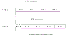
The broadcast time service is a time service mode for determining the current time by reading time information in system information broadcasted by a serving cell through a terminal device and combining a TA from the terminal device to the serving cell, and a basic principle is shown in fig. 4.
The serving cell periodically broadcasts time-related system information in a particular frame (e.g., SFN0 in fig. 4), which includes a time value (e.g., time: 1:00:00:000 as shown in fig. 4) that may be associated with the boundary of the particular frame. After receiving the system information, the terminal device analyzes the time value, and 1/2 × TA is added to the time represented by the time value, that is, the absolute time of the frame boundary associated with the time value is obtained. Wherein, TA is the timing advance from the terminal equipment to the serving cell.
Fig. 5 is a schematic flow chart of a method 500 for acquiring a timing advance TA according to an embodiment of the present application. The method 500 may be performed by a terminal device, or may be performed by a chip or a circuit configured in the terminal device. The method 500 includes the following steps.
S510, receiving first time service information broadcasted by a first cell, and receiving second time service information broadcasted by an adjacent cell.
The first time service information is time information which is broadcasted by the first cell and is used for time service. The second time service information is time information which is broadcasted by the adjacent cell and is used for time service.
For example, the first time service information or the second time service information represents a time value, such as time 1:00:00:000 shown in fig. 4.
As an example, the manner in which the terminal device receives the first time service information may include: and the terminal equipment receives the system information broadcasted by the first cell and analyzes the system information to obtain the first time service information. The manner of receiving the second time service information by the terminal device may include: and the terminal equipment receives the system information broadcasted by the adjacent cell and analyzes the system information to obtain the second time service information.
The sequence of receiving the first time service information and the second time service information is not limited by the application.
The first cell related in this embodiment may be a serving cell of the terminal device, or may also be a certain neighboring cell of which the terminal device has previously known the TA. In summary, the first cell represents a cell in which the terminal device can know the TA, or the TA has been known in advance.
The neighbor cell referred to in the embodiments of the present application denotes a neighbor cell whose TA with the terminal device is to be determined.
S520, the TA from the terminal equipment to the adjacent cell is obtained according to the following information: the time indicated by the first time service information, the TA from the terminal equipment to the first cell, the time difference between the first time service information and the second time service information and the time indicated by the second time service information are received.
The process of acquiring TA from the terminal device to the neighbor cell may include: 1) acquiring absolute time for receiving first time service information according to the TA from the terminal equipment to the first cell and the time indicated by the first time service information; 2) calculating the absolute time of receiving the second time service information according to the absolute time of receiving the first time service information and the time difference between the first time service information and the second time service information; 3) and calculating the TA from the terminal equipment to the adjacent cell according to the absolute time of receiving the second time service information and the time indicated by the second time service information.
Fig. 6 is an example of the above procedure for acquiring TA from the terminal device to the neighboring cell. In fig. 6, it is assumed that the first cell is a serving cell. The terminal device receives the first time service information broadcasted by the service cell and reads the first time (time 1: 1:00:00:000 shown in figure 6), and receives the second time service information broadcasted by the neighbor cell and reads the second time (time 2: 1:00:00:0023 shown in figure 6). The terminal device obtains an absolute time 1 (absolute time 1 is time 1+ TA1/2 as shown in fig. 6) by the first time and a timing advance of the terminal device to the serving cell (TA 1 as shown in fig. 6). Theoretically, an absolute time (denoted as absolute time 2) can also be obtained by the second time and the timing advance of the terminal device to the neighboring cell (as TA2 shown in fig. 6) (as absolute time 2 shown in fig. 6, time 2+ TA 2/2).
Since the absolute time is constant, the timing advance TA2 from the terminal device to the neighbor cell can be calculated according to the following formula:
T1‘+△t=T2’=T2+1/2*TA2,
where T1 'represents absolute time 1, Δ T represents a time difference between the terminal device receiving the first time service information and the second time service information, T2' represents absolute time 2, and T2 represents the second time.
By receiving the time service information of the first cell and the adjacent cell, the TA from the terminal equipment to the adjacent cell can be calculated according to the TA from the terminal equipment to the first cell and the received time service information.
In the positioning scenario shown in fig. 1, if the base station participating in positioning includes a neighboring base station, by applying the scheme provided in the present application, the TA from the terminal device to the neighboring base station can be known, so that the distance from the terminal device to the neighboring base station can be known, and positioning of the terminal device can be further achieved.
In addition, on the premise of not introducing new physical quantity, the TA from the terminal equipment to the adjacent cell can be calculated more simply, and the method is a scheme with a wider application range.
In step S510, the terminal device receives first time service information broadcasted by the first cell according to the time service configuration information of the first cell, and receives second time service information broadcasted by the neighboring cell according to the time service configuration information of the neighboring cell.
The time service configuration information of one cell is used for indicating the time frequency resource of the broadcast time service information of the cell. Namely, the terminal equipment receives the time service information broadcasted by the cell on the time frequency resource indicated by the time service configuration information.
The terminal device should be known for the time service configuration information of the serving cell. For example, the time service configuration information configured by the serving cell is received during the process of accessing the serving cell.
And for the time service configuration information of the adjacent cell, the service base station or the positioning management equipment issues the time service configuration information to the terminal equipment.
In a case where the serving base station does not include a component capable of performing a positioning management function (for example, the serving base station is a gNB shown in fig. 2), a positioning management device of the core network (such as an LMF shown in fig. 2) may collect timing configuration information of a neighboring cell, and send the timing configuration information of the neighboring cell to the terminal device.
In a case where the serving base station includes a component capable of performing a positioning management function (for example, the serving base station is a gNB shown in fig. 3), the serving base station may collect timing configuration information of the neighboring cell and send the timing configuration information of the neighboring cell to the terminal device.
It should be understood that, in the case that the serving base station includes a component capable of assuming a positioning management function, the positioning management device of the core network may also collect the time service configuration information of the neighboring cell and send the time service configuration information of the neighboring cell to the terminal device.
When the network side (serving base station or positioning management device) transmits time service configuration information of a plurality of neighboring cells to the terminal device, the network side should transmit the time service configuration information of each neighboring cell and also transmit a cell identifier (cell ID) of the corresponding cell.
Optionally, in some embodiments, the method 500 further includes: and receiving positioning auxiliary information from the serving cell or the positioning management equipment, wherein the positioning auxiliary information comprises time service configuration information of the adjacent cell.
For example, the positioning assistance information includes timing configuration information of a plurality of neighboring cells and cell IDs of the corresponding neighboring cells.
In the above embodiments related to the time service configuration information, the time service configuration information of a cell is used to indicate the time-frequency resource used by the cell to broadcast the time service information.
For example, the timing configuration information of one cell includes time domain resource configuration information and frequency domain resource configuration information.
As an example, the time service configuration information of one cell includes any one or more of the following information: broadcast period, broadcast window position, frequency domain resource position, etc.
It should be understood that, after receiving the time service configuration information of the neighboring cell from the network side, the terminal device may cache the time service configuration information locally, and may reuse the time service configuration information in the subsequent process of receiving the time service information broadcast by the neighboring cell. That is, the terminal device does not need to receive the time service configuration information of the neighboring cell from the network side before receiving the time service information broadcasted by the neighboring cell every time.
Optionally, in some embodiments, after receiving the time service configuration information of the neighboring cell, if a measurement GAP (measurement GAP) configured for the terminal device by the current serving cell cannot cover a time domain position indicated by the time service configuration information of the neighboring cell, the method 500 further includes: the terminal equipment sends a measurement interval request message to a serving cell, and is used for requesting a measurement interval covering a time domain position of the time service information broadcast by a neighboring cell; and receiving measurement interval configuration information from the serving cell, wherein the measurement interval indicated by the measurement interval configuration information covers the time domain position of the broadcast time service information of the adjacent cell. Wherein, step S510 includes: and the terminal equipment receives second time service information broadcasted by the adjacent cell during the measurement interval indicated by the measurement interval configuration information.
For example, the measurement interval request message carries information indicating the time domain position of the time service information of the neighboring cell.
The measurement interval request message may also carry a cell ID of the neighboring cell.
For another example, the measurement interval request message may carry time domain position information of the time service information of multiple neighboring cells and cell IDs of the neighboring cells.
It should also be understood that, after receiving the time service configuration information of the neighboring cell, if the measurement interval configured for the terminal device by the current serving cell may cover the time domain position indicated by the time service configuration information of the neighboring cell, the terminal device may directly receive the time service information broadcasted by the neighboring cell based on the current measurement interval.
It should also be understood that if the neighboring cell and the serving cell are at the same frequency point, the terminal device does not need to utilize the measurement interval to receive the time service information broadcasted by the neighboring cell, and in this case, the serving base station does not need to request to configure the measurement interval.
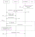
As an example, fig. 7 shows a schematic interaction diagram of a method 700 for acquiring a timing advance TA according to an embodiment of the present application. The method 700 includes the following steps.
S710, the positioning management device collects time service configuration information of one or more neighboring cells (one neighboring cell is shown in fig. 7).
For example, the positioning management device may collect the time service configuration information from the neighboring cells (i.e., neighboring base stations) participating in the positioning of the terminal device.
S720, the positioning management device sends positioning assistance information to the terminal device, where the positioning assistance information includes the time service configuration information of the neighboring cell and the corresponding cell ID acquired in step S710.
After receiving the positioning auxiliary information, the terminal device can acquire the time domain position and the frequency domain position of the broadcast time service information of one or more adjacent cells.
S730, if the current measurement interval of the terminal equipment cannot cover the time domain position of the time service information of one or more adjacent cells, namely the current measurement interval cannot meet the reading of the time service information of one or more adjacent cells, the terminal equipment sends a measurement interval request message to the serving cell, wherein the measurement interval request message comprises the time service configuration information of one or more adjacent cells and corresponding cell IDs.
For example, the measurement interval request message may further include cell frequency information of each neighboring cell.
S740, the serving base station sends measurement interval configuration information to the terminal device based on the measurement interval request message, where the measurement interval indicated by the measurement interval configuration information can cover the time domain position of the time service information of one or more neighboring cells carried in the measurement interval request message.
And S750, the terminal equipment calculates TA from the terminal equipment to each adjacent cell.
Step S750 may be implemented by steps S510 and S520 described above, where the first cell is a serving cell. For details, reference is made to the above description and will not be described in detail here.
S760, the terminal device reports the TA from the terminal device to the neighboring cell obtained in step S750 to the positioning management device.
It should be understood that, the positioning management device may calculate the distance from the terminal device to the neighboring cell according to the TA from the terminal device to the neighboring cell, and further may obtain the positioning of the terminal device based on the geographic location of the neighboring base station.
Alternatively, in some embodiments, steps S730 and S740 may not be performed.
Optionally, in some embodiments, the serving base station (i.e. serving cell) includes a component with a positioning management function, for example, the component is a gNB shown in fig. 3, and then both steps S710 and S720 are performed by the serving cell.
Based on the above description, in the scheme provided by the present application, by receiving the time service information between the first cell and the neighboring cell, the TA from the terminal device to the neighboring cell can be estimated according to the TA from the terminal device to the first cell and the received time service information.
In the positioning scenario shown in fig. 1, if the base station participating in positioning includes a neighboring base station, by applying the scheme provided in the present application, the TA from the terminal device to the neighboring base station can be known, so that the distance from the terminal device to the neighboring base station can be known, and positioning of the terminal device can be further achieved.
In addition, on the premise of not introducing new physical quantity, the TA from the terminal equipment to the adjacent cell can be calculated more simply, and the method is a scheme with a wider application range.
The above describes a scheme for acquiring TA from a terminal device to a neighboring cell based on broadcast timing. In addition, the present application provides another scheme for acquiring a TA from a terminal device to a neighboring cell.
Fig. 8 is a schematic interaction diagram of a method 800 for acquiring a timing advance TA according to another embodiment of the present application. As shown in fig. 8, the method 800 includes the following steps.
S810, the serving cell configures preamble configuration information for the terminal device, where the preamble configuration information indicates a time-frequency resource for the terminal device to transmit a preamble.
For example, the preamble configuration information may include time domain resource configuration information and frequency domain resource configuration information for transmitting the preamble.
For another example, the time-frequency resource for the terminal device to transmit the preamble indicated by the preamble configuration information may be a random access resource.
Optionally, the preamble configuration information may further include sequence information of the preamble.
It should be understood that if the network side and the terminal device agree with the sequence information of the preamble, the preamble configuration information may not carry the sequence information of the preamble.
For example, the serving cell may transmit the preamble configuration information to the terminal device through Radio Resource Control (RRC) signaling.
Alternatively, the preamble indicated by the preamble configuration information may be a dedicated preamble.
Optionally, before step S810, the method may further include: the positioning management device indicates the serving cell and needs to calculate the TA from the terminal device to the neighboring cell.
S820, the serving cell sends the preamble configuration information allocated to the terminal device in step S810 to the positioning management device, and the positioning management device sends the preamble configuration information to the neighboring cell.
The positioning management device may transmit the preamble configuration information to one or more neighbor cells.
For example, the positioning management device may send the preamble configuration information to neighboring cells participating in the positioning of the terminal device.
S830, the terminal equipment sends the lead code according to the lead code configuration information, and the adjacent cell receives the lead code sent by the terminal equipment according to the lead code configuration information.
It should be noted that, the neighboring cell only receives the preamble sent by the terminal device on the time-frequency resource indicated by the preamble configuration information. In other words, on the time-frequency resource indicated by the preamble configuration information, the neighboring cell does not perform signal transmission for other terminal devices.
S840, the adjacent cell measures the received lead code, and obtains the TA from the terminal device to the adjacent cell according to the measurement result and the frame boundary time difference between the adjacent cell and the service cell.
Wherein the frame boundary time difference between the neighbor cell and the serving cell represents the frame edge definition time difference between the neighbor cell and the serving cell, as shown at t1 in fig. 6.
The neighbor cell may autonomously obtain a frame boundary time difference between the neighbor cell and the serving cell.
Or, the serving cell or the positioning management device sends the frame boundary time difference between the neighboring cell and the serving cell to the neighboring cell.
As an example, the frame boundary time difference between two cells is calculated by first equipping a base station in each of the two cells with a Global Positioning System (GPS), and calculating the frame boundary time difference between the two cells from the GPS measurement results of the base stations in the two cells. The present application does not limit the manner of determining the frame boundary time difference between cells.
Optionally, the method may further include: the neighboring cell sends the TA from the terminal device obtained in step S840 to the neighboring cell to the positioning management device.
It should be understood that, the positioning management device may calculate the distance from the terminal device to the neighboring cell according to the TA from the terminal device to the neighboring cell, and further may obtain the positioning of the terminal device based on the geographic location of the neighboring base station.
According to the scheme of the embodiment shown in fig. 8 of the present application, the serving cell sends the preamble configuration information to the terminal device and the neighboring cell, and the neighboring cell can obtain the TA from the terminal device to the neighboring cell by receiving and measuring the preamble sent by the terminal device.
It should be understood that steps S810 and S820 may be performed only once.
For example, the terminal device and the neighboring cell may cache the preamble configuration information locally after receiving it for the first time. In the subsequent signal transmission process based on the preamble configuration information, the preamble configuration information can be directly used for transmitting (terminal device side) and receiving (neighbor cell side) the preamble. I.e. the serving cell does not need to send preamble configuration information to the terminal device and the neighbor cells before each preamble transmission.
Alternatively, in some embodiments, the serving base station (i.e. serving cell) includes a component with positioning management function, such as the gNB shown in fig. 3, then step S820 may be performed by the serving cell.
Optionally, in the embodiment shown in fig. 8, the method further includes: and the serving cell receives the lead code sent by the terminal equipment according to the lead code configuration information, and determines the TA from the terminal equipment to the serving cell according to the measurement of the lead code.
In this embodiment, a serving cell allocates preamble configuration information to a terminal device, and sends the preamble configuration information to the terminal device and a neighboring cell; the terminal device transmits a preamble based on the preamble configuration information, and the serving cell and the neighbor cell receive the preamble based on the preamble configuration information.
In this embodiment, the serving cell and the neighboring cell may both send respective TAs to the positioning management device. The positioning management device may obtain the distance from the terminal device to the serving cell according to the TA of the serving cell, and obtain the distance from the terminal device to the neighboring cell according to the TA of the neighboring cell, so as to obtain the positioning of the terminal device by combining the geographical positions of the serving cell and the neighboring cell.
As an example, as shown in fig. 9, the serving cell, neighbor cell 1, and neighbor cell 2 participate in the positioning of the terminal device. The service cell distributes lead code configuration information for the terminal equipment and sends the lead code configuration information to the terminal equipment, the adjacent cell 1 and the adjacent cell 2; the terminal device transmits a preamble based on the preamble configuration information, and the serving cell, the neighbor cell 1, and the neighbor cell 2 receive the preamble based on the preamble configuration information. The three cells may obtain respective TAs by measuring preambles. The serving cell, the neighboring cell 1, and the neighboring cell 2 transmit their respective TAs to the positioning management device. And the positioning management equipment calculates the distances from the terminal equipment to the serving cell, the adjacent cell 1 and the adjacent cell 2 according to the TA of the serving cell, the TA of the adjacent cell 1 and the TA of the adjacent cell 2. According to the distances from the terminal equipment to the serving cell, the adjacent cell 1 and the adjacent cell 2 and the geographical positions of the serving cell, the adjacent cell 1 and the adjacent cell 2, the terminal equipment can be positioned.
Alternatively, the preamble in the embodiment described in connection with fig. 8 may be replaced with an uplink reference signal. For example, the uplink reference signal may be any one of the following:
sounding Reference Signal (SRS), demodulation reference signal (DMRS), Channel Quality Indicator (CQI), Physical Uplink Shared Channel (PUSCH), and the like.
It should be further understood that the scheme for acquiring the TA from the terminal device to the neighboring cell provided in the present application may be applied to other scenarios that require acquiring the TA from the terminal device to the neighboring cell base station, besides the terminal device positioning scheme shown in fig. 1.
It should also be understood that the various numerical designations of first or second, etc. referred to in this application are merely for convenience of description and are not intended to limit the scope of the embodiments of the application.
The various embodiments described herein may be implemented as stand-alone solutions or combined in accordance with inherent logic and are intended to fall within the scope of the present application.
It is to be understood that, in the above-described method embodiments, the method and the operation implemented by the terminal device may also be implemented by a component (e.g., a chip or a circuit) available for the terminal device, and the method and the operation implemented by the location management device may also be implemented by a component (e.g., a chip or a circuit) available for the location management device.
The method embodiments provided by the embodiments of the present application are described above, and the device embodiments provided by the embodiments of the present application will be described below. It should be understood that the description of the apparatus embodiments corresponds to the description of the method embodiments, and therefore, for brevity, details are not repeated here, since the details that are not described in detail may be referred to the above method embodiments.
The scheme provided by the embodiment of the present application is mainly described from the perspective of interaction among various devices. It is understood that each device, for example, the transmitting end device or the receiving end device, includes a corresponding hardware structure and/or software module for performing each function in order to implement the above functions. Those of skill in the art would appreciate that the various illustrative components and algorithm steps described in connection with the embodiments disclosed herein may be implemented as hardware or combinations of hardware and computer software. Whether a function is performed as hardware or computer software drives hardware depends upon the particular application and design constraints imposed on the solution. Skilled artisans may implement the described functionality in varying ways for each particular application, but such implementation decisions should not be interpreted as causing a departure from the scope of the present application.
In the embodiment of the present application, the functional modules may be divided according to the above method example for the transmitting end device or the receiving end device, for example, each functional module may be divided corresponding to each function, or two or more functions may be integrated into one processing module. The integrated module can be realized in a hardware mode, and can also be realized in a software functional module mode. It should be noted that, in the embodiment of the present application, the division of the module is schematic, and is only one logic function division, and there may be another division manner in actual implementation. The following description will be given taking the example of dividing each functional module corresponding to each function.
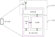
Fig. 10 is a schematic block diagram of a communication device 1000 according to an embodiment of the present application. The communication device 1000 comprises a transceiving unit 1010 and a processing unit 1020. The transceiving unit 1010 may communicate with the outside, and the processing unit 1020 may be configured to perform data processing. The transceiving unit 1010 may also be referred to as a communication interface or a communication unit.
The communication device 1000 may be configured to perform the actions performed by the terminal device in the foregoing method embodiment, or perform the actions performed by the neighboring cell in the foregoing method embodiment, or perform the actions performed by the serving cell in the foregoing method embodiment, or perform the actions performed by the location management device in the foregoing method embodiment.
As one implementation, the communication device 1000 may be configured to perform the actions performed by the terminal device in the above method embodiments. In this implementation, the communication device 1000 may be referred to as a terminal device. The transceiving unit 1010 is configured to perform transceiving related operations on the terminal device side in the above method embodiments, and the processing unit 1020 is configured to perform processing related operations on the terminal device in the above method embodiments.
As a design of this implementation, the transceiver unit 1010 is configured to receive first timing information broadcasted by a first cell and receive second timing information broadcasted by a neighboring cell. A processing unit 1020, configured to obtain a timing advance TA from the terminal device to the neighboring cell according to the following information: the time indicated by the first time service information, the TA from the terminal equipment to the first cell, the time difference between the first time service information and the second time service information and the time indicated by the second time service information are received.
Optionally, the first cell is a serving cell.
Optionally, the transceiving unit 1010 is configured to: receiving positioning auxiliary information from a serving cell or positioning management equipment, wherein the positioning auxiliary information comprises time service configuration information of a neighbor cell, and the time service configuration information is used for indicating time frequency resources of the time service information broadcast by the neighbor cell; and receiving second time service information broadcasted by the adjacent cell based on the time service configuration information.
Optionally, the transceiver unit 1010 is further configured to send a measurement interval request message to the serving cell, where the measurement interval request message is used to request a measurement interval covering a time domain position of the time service information broadcast by the neighboring cell; and receiving measurement interval configuration information from the serving cell, wherein the measurement interval indicated by the measurement interval configuration information covers the time domain position of the broadcast time service information of the adjacent cell. The transceiver unit 1010 is configured to receive second timing information broadcast by a neighboring cell at a measurement interval indicated by the measurement interval configuration information.
As another implementation, the communications apparatus 1000 may be configured to perform the actions performed by the neighboring cells in the above method embodiments. In this implementation, the communication device 1000 may be referred to as a neighbor cell or a network device in a neighbor cell. The transceiver unit 1010 is configured to perform transceiver-related operations of the neighboring cells in the foregoing method embodiments, and the processing unit 1020 is configured to perform processing-related operations of the neighboring cells in the foregoing method embodiments.
As a design in this implementation, the transceiving unit 1010 is configured to: receiving lead code configuration information, wherein the lead code configuration information indicates time-frequency resources of lead codes sent by terminal equipment; and receiving the lead code sent by the terminal equipment according to the lead code configuration information. The processing unit 1020 is configured to measure the received preamble, and obtain a timing advance TA from the terminal device to the neighboring cell according to the measurement result and a frame boundary time difference between the neighboring cell and the serving cell.
Optionally, the transceiving unit 1010 is configured to receive preamble configuration information from a serving cell or a positioning management device.
Optionally, the transceiving unit 1010 is further configured to receive a frame boundary time difference between the neighboring cell and the serving cell from the serving cell or the positioning management device.
It is to be understood that the processing unit 1020 in the above embodiments may be implemented by a processor or processor-related circuitry, and the transceiver unit 1010 may be implemented by a transceiver or transceiver-related circuitry.
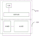
As shown in fig. 11, an embodiment of the present application further provides a communication device 1100. The communication device 1100 comprises a processor 1110, a memory 1120 and a transceiver 1130, the memory 1120 stores programs therein, the processor 1110 is configured to execute the programs stored in the memory 1120, so that the processor 1110 is configured to perform the relevant processing steps in the above method embodiments, and execute the programs stored in the memory 1120, so that the processor 1110 controls the transceiver 1130 to perform the relevant transceiving steps in the above method embodiments.
As an implementation, the communication device 1100 is configured to perform the actions performed by the terminal device in the above method embodiments, at this time, the execution of the program stored in the memory 1120 causes the processor 1110 to perform the processing steps on the terminal device side in the above method embodiments, and the transceiver 1130 is configured to perform the receiving and transmitting steps on the terminal device side in the above method embodiments. Alternatively, execution of the program stored in the memory 1120 causes the processor 1110 to control the transceiver 1130 to perform the receiving and transmitting steps on the terminal device side in the above method embodiments.
As another implementation, the communication device 1100 is configured to perform the actions performed by the neighboring cell in the above method embodiment, and at this time, the execution of the program stored in the memory 1120 causes the processor 1110 to perform the processing steps on the neighboring cell side in the above method embodiment, and the transceiver 1130 is configured to perform the receiving and transmitting steps on the neighboring cell side in the above method embodiment. Optionally, execution of the program stored in the memory 1120 causes the processor 1110 to control the transceiver 1130 to perform the receiving and transmitting steps on the neighbor cell side in the above method embodiments.
As yet another implementation, the communication device 1100 is configured to perform the actions performed by the serving cell in the above method embodiments, at which time the execution of the program stored in the memory 1120 causes the processor 1110 to perform the processing steps of the serving cell side in the above method embodiments, and the transceiver 1130 is configured to perform the receiving and transmitting steps of the serving cell side in the above method embodiments. Optionally, execution of the program stored in the memory 1120 causes the processor 1110 to control the transceiver 1130 to perform the receiving and transmitting steps on the serving cell side in the above method embodiments.
As still another implementation, the communication device 1100 is configured to perform the actions performed by the positioning management device in the above method embodiment, and at this time, the execution of the program stored in the memory 1120 causes the processor 1110 to perform the processing steps of the positioning management device side in the above method embodiment, and the transceiver 1130 is configured to perform the receiving and transmitting steps of the positioning management device side in the above method embodiment. Optionally, execution of the program stored in the memory 1120 causes the processor 1110 to control the transceiver 1130 to perform the receiving and transmitting steps on the side of the location management device in the above-described method embodiments.
The embodiment of the present application further provides a communication apparatus 1200, where the communication apparatus 1200 may be a terminal device or a chip. The communication device 1200 may be used to perform the actions performed by the terminal device in the above-described method embodiments.
When the communication device 1200 is a terminal device, fig. 12 shows a simplified structural diagram of the terminal device. For ease of understanding and illustration, in fig. 12, the terminal device is exemplified by a user device, such as a mobile phone. As shown in fig. 12, the terminal device includes a processor, a memory, a radio frequency circuit, an antenna, and an input-output device. The processor is mainly used for processing communication protocols and communication data, controlling the terminal equipment, executing software programs, processing data of the software programs and the like. The memory is used primarily for storing software programs and data. The radio frequency circuit is mainly used for converting baseband signals and radio frequency signals and processing the radio frequency signals. The antenna is mainly used for receiving and transmitting radio frequency signals in the form of electromagnetic waves. Input and output devices, such as touch screens, display screens, keyboards, etc., are used primarily for receiving data input by a user and for outputting data to the user. It should be noted that some kinds of terminal devices may not have input/output devices.
When data needs to be sent, the processor performs baseband processing on the data to be sent and outputs baseband signals to the radio frequency circuit, and the radio frequency circuit performs radio frequency processing on the baseband signals and sends the radio frequency signals to the outside in the form of electromagnetic waves through the antenna. When data is sent to the terminal equipment, the radio frequency circuit receives radio frequency signals through the antenna, converts the radio frequency signals into baseband signals and outputs the baseband signals to the processor, and the processor converts the baseband signals into the data and processes the data. For ease of illustration, only one memory and processor are shown in FIG. 12, and one or more processors and one or more memories may be present in an actual end device product. The memory may also be referred to as a storage medium or a storage device, etc. The memory may be provided independently of the processor, or may be integrated with the processor, which is not limited in this embodiment.
In the embodiment of the present application, the antenna and the radio frequency circuit having the transceiving function may be regarded as a transceiving unit of the terminal device, and the processor having the processing function may be regarded as a processing unit of the terminal device.
As an example, as shown in fig. 12, an antenna and a radio frequency circuit having a transmitting and receiving function are referred to as a transmitting and receiving unit 1210, and a processor having a processing function is referred to as a processing unit 1220. I.e. the terminal device comprises a transceiving unit 1210 and a processing unit 1220. The transceiver unit 1210 may also be referred to as a transceiver, a transceiving device, etc. The processing unit 1220 may also be referred to as a processor, a processing board, a processing module, a processing device, etc. Alternatively, a device for implementing a receiving function in the transceiver unit 1210 may be regarded as a receiving unit, and a device for implementing a transmitting function in the transceiver unit 1210 may be regarded as a transmitting unit, that is, the transceiver unit 1210 includes a receiving unit and a transmitting unit. A transceiver unit may also sometimes be referred to as a transceiver, transceiving circuitry, or the like. A receiving unit may also be referred to as a receiver, a receiving circuit, or the like. A transmitting unit may also sometimes be referred to as a transmitter, or a transmitting circuit, etc.
For example, in one implementation, the transceiver unit 1210 is further configured to perform a receiving operation on the terminal device side in step S510 shown in fig. 5, and/or the transceiver unit 1210 is further configured to perform other transceiving steps on the terminal device side. The processing unit 1220 is used to perform step S520 shown in fig. 5, and/or the processing unit 1220 is also used to perform other processing steps on the terminal device side.
For another example, in an implementation, the transceiver 1210 is further configured to perform a receiving operation on the terminal device side in steps S720, S740, and S750 shown in fig. 7, the transceiver 1210 is further configured to perform a transmitting operation on the terminal device side in steps S730 and S760 shown in fig. 7, and/or the transceiver 1210 is further configured to perform other transceiving steps on the terminal device side. The processing unit 1220 is used to perform step S750 shown in fig. 7, and/or the processing unit 1220 is also used to perform other processing steps on the terminal device side.
For another example, in an implementation manner, the transceiver unit 1210 is further configured to perform a receiving operation on the terminal device side in step S810 shown in fig. 8, the transceiver unit 1210 is further configured to perform a transmitting operation on the terminal device side in step S830 shown in fig. 8, and/or the transceiver unit 1210 is further configured to perform other transceiving steps on the terminal device side. The processing unit 1220 is configured to perform the processing operation on the terminal device side in step S830 shown in fig. 8, for example, determine the time-frequency resource for transmitting the preamble according to the preamble configuration information, and/or the processing unit 1220 is further configured to perform other processing steps on the terminal device side.
It should be understood that fig. 12 is only an example and not a limitation, and the terminal device including the transceiving unit and the processing unit described above may not depend on the structure shown in fig. 12.
When the communication device 1200 is a chip, the chip includes a transceiving unit and a processing unit. The transceiving unit can be an input/output circuit or a communication interface; the processing unit may be a processor or a microprocessor or an integrated circuit integrated on the chip.
The embodiment of the present application further provides a communication device 1300, where the communication device 1300 may be a network device or a chip. The communication device 1300 may be configured to perform the actions performed by the neighboring cells in the above method embodiments, or perform the actions performed by the serving cell in the above method embodiments, or perform the actions performed by the location management device in the above method embodiments.
When the communication device 1300 is a network device, for example, a base station. Fig. 13 shows a simplified base station structure. The base station includes a 1310 portion and a 1320 portion. The 1310 part is mainly used for receiving and transmitting radio frequency signals and converting the radio frequency signals and baseband signals; part 1320 is mainly used for baseband processing, base station control, and the like. Portion 1310 may be generally referred to as a transceiver unit, transceiver, transceiving circuitry, or transceiver, etc. Part 1320 is generally a control center of the base station, and may be generally referred to as a processing unit, for controlling the base station to perform the processing operations on the network device side in the above method embodiments.
The transceiver unit of part 1310, which may also be referred to as a transceiver or transceiver, includes an antenna and a radio frequency unit, wherein the radio frequency unit is mainly used for radio frequency processing. Alternatively, the device for implementing the receiving function in the portion 1310 may be regarded as a receiving unit, and the device for implementing the transmitting function may be regarded as a transmitting unit, that is, the portion 1310 includes a receiving unit and a transmitting unit. A receiving unit may also be referred to as a receiver, a receiving circuit, or the like, and a transmitting unit may be referred to as a transmitter, a transmitting circuit, or the like.
For example, in an implementation manner, the transceiver unit of part 1310 is configured to perform the transmission operation on the neighboring cell side in steps S710 and S750 in fig. 7, and/or the transceiver unit of part 1310 is further configured to perform other transceiving steps on the neighboring cell side in this embodiment. The processing unit in part 1320 is configured to perform the processing steps on the neighboring cell side in the embodiment of the present application.
For another example, in another implementation manner, the transceiver unit of the part 1310 is configured to perform the receiving operation of the neighboring cell side in steps S820 and S830 in fig. 8, and/or the transceiver unit of the part 1310 is further configured to perform other transceiving steps of the neighboring cell side in this embodiment. The processing unit of part 1320 is configured to execute step S840 in fig. 8.
For another example, in another implementation manner, the transceiver unit of the part 1310 is configured to perform the transmission operation on the serving cell side in steps S740 and S750 in fig. 7, the transceiver unit of the part 1310 is configured to perform the receiving operation on the serving cell side in step S730 in fig. 7, and/or the transceiver unit of the part 1310 is further configured to perform other transceiving steps on the serving cell side in this embodiment of the application. The processing unit of part 1320 is configured to perform the processing steps on the serving cell side in the embodiment of the present application.
For another example, in another implementation manner, the transceiver unit of the part 1310 is configured to perform the transmission operation on the serving cell side in steps S810 and S820 in fig. 8, and/or the transceiver unit of the part 1310 is further configured to perform other transceiving steps on the serving cell side in this embodiment of the present application. The processing unit of part 1320 is configured to perform the processing steps on the serving cell side in the embodiment of the present application.
It should be understood that fig. 13 is only an example and not a limitation, and the network device including the transceiving unit and the processing unit may not depend on the structure shown in fig. 13.
When the communication device 1300 is a chip, the chip includes a transceiving unit and a processing unit. The transceiver unit can be an input/output circuit and a communication interface; the processing unit is a processor or a microprocessor or an integrated circuit integrated on the chip.
An embodiment of the present application further provides a communication system, where the communication system includes the positioning management device, the serving cell, the neighboring cell, and the terminal device in the foregoing embodiment.
An embodiment of the present application further provides a computer-readable storage medium, on which a computer program is stored, and when the computer program is executed by a computer, the computer implements the method on the terminal device side, or the method on the neighboring cell side, or the method on the serving cell side, or the method on the positioning management device side in the foregoing method embodiments.
An embodiment of the present application further provides a computer program product containing instructions, where the instructions, when executed by a computer, cause the computer to implement the method on the terminal device side, the method on the neighboring cell side, the method on the serving cell side, or the method on the positioning management device side in the foregoing method embodiments.
For the explanation and beneficial effects of the related content in any of the communication apparatuses provided above, reference may be made to the corresponding method embodiments provided above, and details are not repeated here.
In the embodiment of the application, the terminal device or the network device includes a hardware layer, an operating system layer running on the hardware layer, and an application layer running on the operating system layer. The hardware layer includes hardware such as a Central Processing Unit (CPU), a Memory Management Unit (MMU), and a memory (also referred to as a main memory). The operating system may be any one or more computer operating systems that implement business processing through processes (processes), such as a Linux operating system, a Unix operating system, an Android operating system, an iOS operating system, or a windows operating system. The application layer comprises applications such as a browser, an address list, word processing software, instant messaging software and the like. Furthermore, the embodiment of the present application does not particularly limit the specific structure of the execution main body of the method provided by the embodiment of the present application, as long as the communication can be performed according to the method provided by the embodiment of the present application by running the program recorded with the code of the method provided by the embodiment of the present application, for example, the execution main body of the method provided by the embodiment of the present application may be a terminal device or a network device, or a functional module capable of calling the program and executing the program in the terminal device or the network device.
In addition, various aspects or features of the present application may be implemented as a method, apparatus, or article of manufacture using standard programming and/or engineering techniques. The term "article of manufacture" as used herein is intended to encompass a computer program accessible from any computer-readable device, carrier, or media. For example, computer-readable media may include, but are not limited to: magnetic storage devices (e.g., hard disk, floppy disk, or magnetic tape), optical disks (e.g., Compact Disk (CD), Digital Versatile Disk (DVD), etc.), smart cards, and flash memory devices (e.g., erasable programmable read-only memory (EPROM), card, stick, or key drive, etc.). In addition, various storage media described herein can represent one or more devices and/or other machine-readable media for storing information. The term "machine-readable medium" can include, without being limited to, wireless channels and various other media capable of storing, containing, and/or carrying instruction(s) and/or data.
It should be understood that the processor mentioned in the embodiments of the present application may be a Central Processing Unit (CPU), and may also be other general purpose processors, Digital Signal Processors (DSPs), Application Specific Integrated Circuits (ASICs), Field Programmable Gate Arrays (FPGAs) or other programmable logic devices, discrete gate or transistor logic devices, discrete hardware components, and the like. A general purpose processor may be a microprocessor or the processor may be any conventional processor or the like.
It will also be appreciated that the memory referred to in the embodiments of the application may be either volatile memory or nonvolatile memory, or may include both volatile and nonvolatile memory. The non-volatile memory may be a read-only memory (ROM), a Programmable ROM (PROM), an Erasable PROM (EPROM), an electrically Erasable EPROM (EEPROM), or a flash memory. Volatile memory can be Random Access Memory (RAM), which acts as external cache memory. By way of example, but not limitation, many forms of RAM are available, such as Static Random Access Memory (SRAM), Dynamic Random Access Memory (DRAM), Synchronous Dynamic Random Access Memory (SDRAM), double data rate SDRAM, enhanced SDRAM, SLDRAM, Synchronous Link DRAM (SLDRAM), and direct rambus RAM (DR RAM).
It should be noted that when the processor is a general-purpose processor, a DSP, an ASIC, an FPGA or other programmable logic device, a discrete gate or transistor logic device, or a discrete hardware component, the memory (memory module) is integrated in the processor.
It should be noted that the memory described herein includes, but is not limited to, the above memory, and may include any other suitable type of memory.
Those of ordinary skill in the art would appreciate that the various illustrative elements and algorithm steps described in connection with the embodiments disclosed herein may be implemented as electronic hardware or combinations of computer software and electronic hardware. Whether such functionality is implemented as hardware or software depends upon the particular application and design constraints imposed on the implementation. Skilled artisans may implement the described functionality in varying ways for each particular application, but such implementation decisions should not be interpreted as causing a departure from the scope of the present application.
It is clear to those skilled in the art that, for convenience and brevity of description, the specific working processes of the above-described systems, apparatuses and units may refer to the corresponding processes in the foregoing method embodiments, and are not described herein again.
In the several embodiments provided in the present application, it should be understood that the provided system, apparatus and method may be implemented in other ways. For example, the above-described apparatus embodiments are merely illustrative, and for example, the above-described division of units is only one type of division of logical functions, and there may be other divisions when actually implemented, for example, a plurality of units or components may be combined or may be integrated into another system, or some features may be omitted, or not executed. In addition, the shown or discussed mutual coupling or direct coupling or communication connection may be an indirect coupling or communication connection through some interfaces, devices or units, and may be in an electrical, mechanical or other form.
The units described above as separate parts may or may not be physically separate, and parts displayed as units may or may not be physical units, may be located in one place, or may be distributed on a plurality of network units. Some or all of the units can be selected according to actual needs to achieve the technical effect of the scheme of the embodiment.
In addition, functional units in the embodiments of the present application may be integrated into one processing unit, or each unit may exist alone physically, or two or more units are integrated into one unit.
The above-described functions, if implemented in the form of software functional units and sold or used as a separate product, may be stored in a computer-readable storage medium. Based on such understanding, the technical solution of the present application or portions thereof that substantially contribute to the prior art may be embodied in the form of a software product stored in a storage medium and including instructions for causing a computer device (which may be a personal computer, a server, or a network device) to execute all or part of the steps of the method of the embodiments of the present application. And the aforementioned storage medium includes: various media capable of storing program codes, such as a usb disk, a removable hard disk, a read-only memory (ROM), a Random Access Memory (RAM), a magnetic disk, or an optical disk.
The above description is only for the specific embodiments of the present application, but the scope of the present application is not limited thereto, and any changes or substitutions that can be easily conceived by those skilled in the art within the technical scope of the present application are intended to be covered by the scope of the present application. Therefore, the protection scope of the present application shall be subject to the protection scope of the claims.
Claims (11)
1. A method for obtaining a timing advance, TA, comprising:
the terminal equipment receives first time service information broadcasted by a first cell and receives second time service information broadcasted by an adjacent cell;
and obtaining the TA from the terminal equipment to the adjacent cell according to the following information: the time indicated by the first time service information, the TA from the terminal equipment to the first cell, the time difference between the first time service information and the second time service information and the time indicated by the second time service information are received.
2. The method of claim 1, wherein the receiving the second timing information broadcasted by the neighboring cell comprises:
receiving positioning auxiliary information from a serving cell or positioning management equipment, wherein the positioning auxiliary information comprises time service configuration information of the adjacent cell, and the time service configuration information is used for indicating time frequency resources of the time service information broadcast by the adjacent cell;
and receiving the second time service information broadcasted by the adjacent cell based on the time service configuration information.
3. The method of claim 1, further comprising:
sending a measurement interval request message to a serving cell, wherein the measurement interval request message is used for requesting a measurement interval covering the time domain position of the time service information broadcast by the neighbor cell;
receiving measurement interval configuration information from a serving cell, wherein a measurement interval indicated by the measurement interval configuration information covers a time domain position of the broadcast time service information of the neighboring cell;
the receiving of the second time service information broadcasted by the neighboring cell includes:
and receiving the second timing information broadcasted by the neighbor cell during the measurement interval indicated by the measurement interval configuration information.
4. The method according to any of claims 1 to 3, wherein the first cell is a serving cell.
5. A terminal device, comprising:
the receiving and sending unit is used for receiving first time service information broadcasted by a first cell and receiving second time service information broadcasted by an adjacent cell;
a processing unit, configured to obtain a timing advance TA from the terminal device to the neighboring cell according to the following information: the time indicated by the first time service information, the TA from the terminal equipment to the first cell, the time difference between the first time service information and the second time service information and the time indicated by the second time service information are received.
6. The terminal device according to claim 5, wherein the transceiver unit is configured to:
receiving positioning auxiliary information from a serving cell or positioning management equipment, wherein the positioning auxiliary information comprises time service configuration information of the adjacent cell, and the time service configuration information is used for indicating time frequency resources of the time service information broadcast by the adjacent cell;
and receiving the second time service information broadcasted by the adjacent cell based on the time service configuration information.
7. The terminal device according to claim 5, wherein the transceiver unit is further configured to send a measurement interval request message to a serving cell, for requesting a measurement interval covering a time domain position of the time service information broadcast by the neighboring cell; receiving measurement interval configuration information from a serving cell, wherein a measurement interval indicated by the measurement interval configuration information covers a time domain position of the broadcast time service information of the neighboring cell;
the transceiver unit is configured to receive the second timing information broadcast by the neighboring cell during a measurement interval indicated by the measurement interval configuration information.
8. The terminal device of any of claims 5-7, wherein the first cell is a serving cell.
9. A communications apparatus, comprising a memory to store instructions and a processor to execute the instructions stored by the memory, wherein execution of the instructions stored in the memory causes the processor to perform the method of any of claims 1 to 4.
10. A computer-readable storage medium, having stored thereon a computer program which, when executed by a computer, causes the computer to carry out the method of any one of claims 1 to 4.
11. A communication system comprising a location management device, a serving cell, a neighbor cell, and a terminal device according to any one of claims 5 to 8.
Priority Applications (5)
| Application Number | Priority Date | Filing Date | Title |
|---|---|---|---|
| CN201910361638.0A CN111865529B (en) | 2019-04-30 | 2019-04-30 | Method and device for acquiring time advance |
| CA3138375A CA3138375A1 (en) | 2019-04-30 | 2020-03-12 | Method for obtaining timing advance and apparatus |
| EP20798537.5A EP3955500A4 (en) | 2019-04-30 | 2020-03-12 | Method and apparatus for obtaining timing advance |
| PCT/CN2020/078964 WO2020220839A1 (en) | 2019-04-30 | 2020-03-12 | Method and apparatus for obtaining timing advance |
| US17/514,200 US20220053437A1 (en) | 2019-04-30 | 2021-10-29 | Method for obtaining timing advance and apparatus |
Applications Claiming Priority (1)
| Application Number | Priority Date | Filing Date | Title |
|---|---|---|---|
| CN201910361638.0A CN111865529B (en) | 2019-04-30 | 2019-04-30 | Method and device for acquiring time advance |
Publications (2)
| Publication Number | Publication Date |
|---|---|
| CN111865529A CN111865529A (en) | 2020-10-30 |
| CN111865529B true CN111865529B (en) | 2021-12-03 |
Family
ID=72965606
Family Applications (1)
| Application Number | Title | Priority Date | Filing Date |
|---|---|---|---|
| CN201910361638.0A Active CN111865529B (en) | 2019-04-30 | 2019-04-30 | Method and device for acquiring time advance |
Country Status (5)
| Country | Link |
|---|---|
| US (1) | US20220053437A1 (en) |
| EP (1) | EP3955500A4 (en) |
| CN (1) | CN111865529B (en) |
| CA (1) | CA3138375A1 (en) |
| WO (1) | WO2020220839A1 (en) |
Families Citing this family (2)
| Publication number | Priority date | Publication date | Assignee | Title |
|---|---|---|---|---|
| WO2023178697A1 (en) * | 2022-03-25 | 2023-09-28 | Oppo广东移动通信有限公司 | Information processing method and terminal device |
| JP2024044135A (en) * | 2022-09-20 | 2024-04-02 | Kddi株式会社 | Base station device, control method, and program for estimating the position of a terminal device |
Citations (6)
| Publication number | Priority date | Publication date | Assignee | Title |
|---|---|---|---|---|
| CN102281626A (en) * | 2011-07-06 | 2011-12-14 | 电信科学技术研究院 | Method and device for determining uplink timing advance |
| CN102740443A (en) * | 2011-04-02 | 2012-10-17 | 华为技术有限公司 | Method for acquiring secondary timing advance and equipment |
| EP2693826A1 (en) * | 2011-03-31 | 2014-02-05 | China Academy of Telecommunications Technology | Method and device for random access based on multiple uplink timing advances |
| WO2014067475A1 (en) * | 2012-10-31 | 2014-05-08 | 华为技术有限公司 | Method and device for transmitting uplink data in carrier aggregation |
| CN106470413A (en) * | 2015-08-14 | 2017-03-01 | 中兴通讯股份有限公司 | The processing method and processing device of neighbouring business in multicarrier |
| CN109526001A (en) * | 2017-09-19 | 2019-03-26 | 中国移动通信有限公司研究院 | A kind of measurement method, base station, terminal and communication equipment |
Family Cites Families (13)
| Publication number | Priority date | Publication date | Assignee | Title |
|---|---|---|---|---|
| EP2557867A1 (en) * | 2011-08-11 | 2013-02-13 | Panasonic Corporation | Timing advance configuration for multiple uplink component carriers |
| EP2772086B1 (en) * | 2011-10-24 | 2017-08-23 | Telefonaktiebolaget LM Ericsson (publ) | A radio network node, a network management node and methods therein |
| US11943813B2 (en) * | 2012-04-01 | 2024-03-26 | Comcast Cable Communications, Llc | Cell grouping for wireless communications |
| EP3982678A3 (en) * | 2012-04-01 | 2022-08-03 | Comcast Cable Communications, LLC | Cell group timing adjustment for wireless communications |
| US11252679B2 (en) * | 2012-04-16 | 2022-02-15 | Comcast Cable Communications, Llc | Signal transmission power adjustment in a wireless device |
| US11582704B2 (en) * | 2012-04-16 | 2023-02-14 | Comcast Cable Communications, Llc | Signal transmission power adjustment in a wireless device |
| WO2014027942A1 (en) * | 2012-08-13 | 2014-02-20 | Telefonaktiebolaget L M Ericsson (Publ) | Enhancing positioning with transmit-timing adjustment information |
| US20150327198A1 (en) * | 2014-05-12 | 2015-11-12 | Telefonaktiebolaget L M Ericsson (Publ) | Handling of Cells Associated with Timing Advance Groups in a Wireless Communications System |
| CN107371273B (en) * | 2016-05-13 | 2023-05-30 | 中兴通讯股份有限公司 | Random access method, device and user equipment |
| EP3501215B1 (en) * | 2016-08-17 | 2021-04-28 | Nokia Solutions and Networks Oy | Interface enhancements for timing advance-based multilateration for user device positioning measurements |
| EP3536044A1 (en) * | 2016-11-03 | 2019-09-11 | Telefonaktiebolaget LM Ericsson (publ) | Positioning procedure for relaxed mobility iot devices |
| US11632806B2 (en) * | 2018-08-10 | 2023-04-18 | Sony Corporation | Communications device, infrastructure equipment and methods |
| US11153840B2 (en) * | 2019-03-28 | 2021-10-19 | Mediatek Inc. | UE feedback of timing adjustment after a measurement gap |
-
2019
- 2019-04-30 CN CN201910361638.0A patent/CN111865529B/en active Active
-
2020
- 2020-03-12 WO PCT/CN2020/078964 patent/WO2020220839A1/en unknown
- 2020-03-12 CA CA3138375A patent/CA3138375A1/en active Pending
- 2020-03-12 EP EP20798537.5A patent/EP3955500A4/en active Pending
-
2021
- 2021-10-29 US US17/514,200 patent/US20220053437A1/en active Pending
Patent Citations (6)
| Publication number | Priority date | Publication date | Assignee | Title |
|---|---|---|---|---|
| EP2693826A1 (en) * | 2011-03-31 | 2014-02-05 | China Academy of Telecommunications Technology | Method and device for random access based on multiple uplink timing advances |
| CN102740443A (en) * | 2011-04-02 | 2012-10-17 | 华为技术有限公司 | Method for acquiring secondary timing advance and equipment |
| CN102281626A (en) * | 2011-07-06 | 2011-12-14 | 电信科学技术研究院 | Method and device for determining uplink timing advance |
| WO2014067475A1 (en) * | 2012-10-31 | 2014-05-08 | 华为技术有限公司 | Method and device for transmitting uplink data in carrier aggregation |
| CN106470413A (en) * | 2015-08-14 | 2017-03-01 | 中兴通讯股份有限公司 | The processing method and processing device of neighbouring business in multicarrier |
| CN109526001A (en) * | 2017-09-19 | 2019-03-26 | 中国移动通信有限公司研究院 | A kind of measurement method, base station, terminal and communication equipment |
Non-Patent Citations (3)
| Title |
|---|
| Discussion on RACH based solution and Timing difference based solution;Renesas Mobile Europe;《3GPP TSG-RAN WG2 Meeting #74》;20110513;第1-4页 * |
| Discussion on Timing Advance calculation using time difference measurement;InterDigital Communications, LLC;《3GPP TSG-RAN WG1 Meeting #66》;20110826;全文 * |
| Renesas Mobile Europe.Discussion on RACH based solution and Timing difference based solution.《3GPP TSG-RAN WG2 Meeting #74》.2011, * |
Also Published As
| Publication number | Publication date |
|---|---|
| WO2020220839A1 (en) | 2020-11-05 |
| EP3955500A4 (en) | 2022-11-16 |
| EP3955500A1 (en) | 2022-02-16 |
| US20220053437A1 (en) | 2022-02-17 |
| CA3138375A1 (en) | 2020-11-05 |
| CN111865529A (en) | 2020-10-30 |
Similar Documents
| Publication | Publication Date | Title |
|---|---|---|
| CN111586855B (en) | Signal transmission method and device | |
| US20220279313A1 (en) | Sidelink Positioning Method and Apparatus | |
| CN113114439B (en) | Method and device for positioning | |
| CN110730501B (en) | Positioning method, device and equipment | |
| CN111526575B (en) | Method and device for transmitting signals | |
| CN111866926B (en) | Method and device for reporting measurement | |
| CN112449370A (en) | Positioning method and communication device | |
| CN111586831A (en) | Signal transmission method and device | |
| CN110035444B (en) | Resource determination method and device | |
| CN111615811B (en) | Communication method and communication device | |
| EP4149181A1 (en) | Method for determining time advance (ta), and network device and terminal | |
| CN113645657B (en) | Wireless communication method, terminal equipment and network equipment | |
| US20230063450A1 (en) | Positioning Capabilities of Reduced Capability New Radio Devices | |
| CN115499113A (en) | Wireless communication method, terminal equipment and network equipment | |
| US20220053437A1 (en) | Method for obtaining timing advance and apparatus | |
| CN109644426B (en) | Method and equipment for receiving information and sending information | |
| CN113518420B (en) | Communication method and communication device | |
| CN116234021A (en) | Wireless communication method, terminal device and network device | |
| CN110073702A (en) | The method and apparatus of wireless communication | |
| CN114401556B (en) | Wireless communication method, terminal device and network device | |
| EP3437383B1 (en) | Method for performing random access, and associated terminal device | |
| CN115428349A (en) | Signal measurement method, terminal equipment and network equipment | |
| CN114175793A (en) | Wireless communication method and terminal device | |
| EP4061075A1 (en) | Wireless communication method and apparatus |
Legal Events
| Date | Code | Title | Description |
|---|---|---|---|
| PB01 | Publication | ||
| PB01 | Publication | ||
| SE01 | Entry into force of request for substantive examination | ||
| SE01 | Entry into force of request for substantive examination | ||
| GR01 | Patent grant | ||
| GR01 | Patent grant |