Disclosure of Invention
The purpose of the invention is as follows: the invention provides a data-based calculation method for the service life of an exhaust temperature margin of an aircraft engine, aiming at solving the problems that in the prior art, the calculation of EGTM has large subjective factors and large fluctuation of conversion results.
The technical scheme is as follows: the invention provides a data-based calculation method for the exhaust temperature margin life of an aircraft engine, which specifically comprises the following steps:
step 1: acquiring aircraft engine data, comprising: the method comprises the following steps of (1) setting total atmospheric temperature TAT, indicating fan rotating speed N1, engine exhaust temperature EGT, variable bleed valve position VBV, adjustable stator blade position VSV, low-pressure turbine gap control valve position LPTACC, high-pressure turbine gap control valve position HPTACC, high-pressure engine bleed valve HPV, engine bleed pressure adjusting valve PRV, cabin deicing valve position Nacelle, Wing deicing valve position Wing and air conditioner assembly flow Pack;
step 2: establishing an aircraft engine fan rotating speed correction model, which specifically comprises the following steps: working condition conversion is carried out on the rotating speed standard of the engine fan according to the atmospheric total temperature TAT to obtain a corrected value N1K of the rotating speed of the indicated fan, thrust management conversion is carried out on the rotating speed of the engine fan according to a balance value of the rotating speed of the engine fan and N1K of the engine fan, and therefore the actual rotating speed N1K of the fan is obtained through calculationACT;
And step 3: establishing an aircraft engine exhaust temperature correction model, specifically: according to the collected engine exhaust temperature EGT, carrying out working condition conversion on an engine exhaust temperature standard to obtain an exhaust temperature conversion value EGTK; putting EGTK and VBV, VSV, LPTACC, HPTACC, HPV, PRV, Nacelle, Wing and Pack obtained in the step 1 into a trained support vector machine to obtain a corrected exhaust temperature conversion value EGTKC;
and 4, step 4: N1K obtained according to step 2ACTObtaining the threshold value of the exhaust temperature of the engine, and determining the inflection point temperature T of the exhaust of the engine according to the type of the engineCORNEREGTKC and T calculated according to step 4CORNERObtaining the actual exhaust temperature margin EGTM of the engine;
and 5: establishing an aircraft engine margin residual life model, specifically: and (4) extracting the characteristic value of the EGTM in the step (4), and obtaining the margin residual life of the aircraft engine according to the extracted characteristic signal.
Further, the step 2 specifically comprises:
the standard working condition of the rotating speed of the engine fan is converted into:
calculating a temperature conversion ratio theta according to the collected total atmospheric temperature:
solving the following equation according to theta and the collected indicated fan speed N1:
the value range of N1K is 3000-5205200, the equation is solved according to the value range, and N1K is obtained through calculation;
the management conversion of the rotating speed and the thrust of the engine fan is as follows:
a Trim value Trim of an engine fan speed is determined according to the type of the engine, and a Trim effect correction value DeltaN 1 indicating a fan speed N1 is determined according to the following formulaCtrim:
When Trim is 0, Δ N1Ctrim=0;
When Trim is 1, Δ N1Ctrim=2.301·10-8·N1K3-2.92·10-4·N1K2+1.236·N1K-1737;
When Trim is 2, Δ N1Ctrim=4.602·10-8·N1K3-5.84·10-4·N1K2+2.471·N1K-3475;
When Trim is 3, Δ N1Ctrim=6.903·10-8·N1K3-8.76·10-4·N1K2+3.707·N1K-5212;
When Trim is 4, Δ N1Ctrim=9.585·10-8·N1K3-1.22·10-3·N1K2+5.167·N1K-7275;
When Trim is 5, Δ N1Ctrim=1.189·10-7·N1K3-1.51·10-3·N1K2+6.403·N1K-9013;
When Trim is 6, Δ N1Ctrim=1.527·10-7·N1K3-1.94·10-3·N1K2+8.224·N1K-11580;
When Trim is 7, Δ N1Ctrim=2.032·10-7·N1K3-2.58·10-3·N1K2+10.93·N1K-15380;
According to the calculated N1K and delta N1Ctrim, calculating the difference between the twoDifference between N1Ktrim:
According to the calculated N1KtrimCalculating a rotation speed conversion index alpha:
α=-1.363·10-8N1Ktrim 2+8.791·10-5N1Ktrim+0.3579;
according to the calculated N1KtrimTheta and alpha, and calculating the actual rotating speed N1K of the fanACT;
Further, the step 3 specifically includes: the EGTK is obtained by calculating according to the following formula
Wherein theta is a temperature conversion ratio;
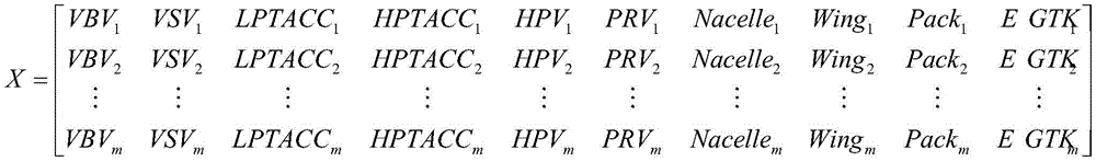
collecting m sets of historical data of the engine, the historical data comprising: the system comprises an engine exhaust temperature, a variable bleed valve position, an adjustable stator blade position, a low-pressure turbine gap control valve position, a high-pressure turbine gap control valve position, an engine high-pressure bleed valve, an engine bleed pressure adjusting valve, a cabin deicing valve position, a wing deicing valve position and an air conditioner component flow rate; obtaining m groups of exhaust temperature conversion values according to m groups of engine exhaust temperatures in historical data; the support vector machine model learning matrix is constructed as follows:
wherein X is the input vector of the support vector machine, Y is the output vector of the support vector machine, VBVmAs the mth group history numberAccording to the position of the variable bleed valve, VSVmFor the adjustable stator vane position, LPTACC, in the mth set of historical datamControl valve position, HPTACC for low pressure turbine clearance in mth set of historical datamControl flap position, HPV for high pressure turbine gap in mth set of historical datamFor the high pressure bleed air valve, PRV of the engine in the mth group of historical datamAdjusting valve, Nacelle for bleed air pressure of engine in mth group of historical datamFor the passenger cabin deicing valve position, Wing in the mth group of historical datamPack for wing de-icing valve position in mth set of historical datamThe flow rate of the air-conditioning component and the EGTK in the mth group of historical datamEGTKC as a group m exhaust gas temperature equivalentmA preset mth corrected exhaust gas temperature conversion value based on the mth group of history data;
a penalty factor and kernel function parameters based on a radial basis kernel function in a support vector machine are optimized through a genetic algorithm to obtain a corrected training model of the air entraining system;
and (3) putting the VBV, VSV, LPTACC, HPTACC, HPV, PRV, Nacelle, Wing and Pack collected in the step (1) into the bleed air system correction training model to obtain a corrected exhaust temperature conversion value EGTKC.
Further, the step 4 specifically includes: the threshold value of the engine exhaust gas temperature is EGTLIM:
EGTLIM=0.2044·N1KACT-99.75;
EGTKC calculated in step 3, and inflection point temperature T of engine exhaustCORNERThe exhaust gas temperature EGT of the engine at the inflection point temperature is calculated based on the following formulaCORNER:
Mixing EGTLIMAnd EGTCORNERAs engine exhaust gas temperature margin EGTM before correctionr;
According to the type of the engine, obtaining the correction coefficient gamma of the exhaust gas temperature margin of the engine, and calculating the actual exhaust gas temperature margin EGTM of the engine based on the following formula:
EGTM=(EGTLIM-EGTCORNER)·γ。
further, the step 5 specifically includes: carrying out wavelet transformation processing on the EGTM in the step 4 by adopting a multi-Beth 3-order wavelet filter to obtain an EGTM characteristic signal; fitting the characteristic signal by adopting a linear function to obtain a regression curve: the EGTM is k.x + b, wherein K is the fading rate, the value of b is the initial EGTM of the engine, and the margin residual life K of the aircraft engine is calculated based on the fading ratelife:
Has the advantages that: the invention provides a method for calculating the exhaust temperature margin life of an aircraft engine, which realizes the whole process calculation from data acquisition to residual life prediction and solves the problem of difficulty in calculating the exhaust temperature margin of the existing aircraft engine.
Detailed Description
The accompanying drawings, which are incorporated in and constitute a part of this specification, illustrate an embodiment of the invention and, together with the description, serve to explain the invention and not to limit the invention.
As shown in fig. 1, the embodiment provides a method for calculating an aircraft engine exhaust temperature margin life based on data, which specifically includes the following steps:
A. selecting aeroengine data;
B. constructing a fan rotating speed correction model of the aircraft engine;
C. constructing a temperature correction model of exhaust temperature at the inflection point temperature of the aircraft engine;
D. calculating the relevant exhaust temperature value of the aircraft engine;
E. and constructing a margin residual life model of the aero-engine.
The engine in this embodiment is model CFM 56-5B.
The step A specifically comprises the following steps: selection of aircraft communication addressing and reporting system (aircraft communication addressing and reporting system) data
Selecting relevant parameter values in a takeoff report of the aircraft communication addressing and reporting system based on the data of the aircraft communication addressing and reporting system, wherein the parameter values comprise: total Air Temperature (TAT), Indicated Fan Speed (N1), Engine Exhaust Temperature (EGT), variable Bleed Valve Position (VBV Position, VBV), adjustable stator blade Position (VSV Position, VSV), low Pressure turbine clearance control Valve Position (LPT ACC Position, LPTACC), High Pressure turbine clearance control Valve Position (HPT ACC Position, HPTACC), High Pressure Bleed Valve (blade Engine High Pressure Valve, HPV), Bleed Air Pressure Regulating Valve (PRV), ANTI-ICE Valve Position (ANTI-Ice Valve Position, wind Air conditioner assembly (wind Air conditioner), pack for short); as shown in Table 1
TABLE 1
| Parameter name
|
Parameter explanation
|
Unit of
|
| Total Air Temperature
|
Total temperature of atmosphere
|
℃
|
| Indicated Fan Speed
|
Indicating fan speed
|
%
|
| Exhaust Gas Temperature
|
Exhaust temperature of engine
|
℃
|
| VBV Position
|
Variable bleed valve position
|
°
|
| VSV Position
|
Adjustable stator vane position
|
°
|
| LPT ACC Position
|
Low pressure turbine clearance control valve position
|
%
|
| HPT ACC Position
|
High pressure turbine clearance control valve position
|
%
|
| Bleed Engine High Pressure Valve
|
Engine high pressure bleed valve (switching value)
|
/
|
| Bleed Engine Pressure Regulating Valve
|
Engine bleed air pressure regulating valve (switching value)
|
/
|
| ANTI-ICE Valve Position Nacelle
|
Cabin deicing valve position (switching value)
|
/
|
| ANTI-ICE valve position Wing
|
Position of wing deicing valve (switching value)
|
/
|
| Air Conditioning Pack Flow
|
Air conditioner component flow
|
KG/SEC |
The step B specifically comprises the following steps:
selection of basic information data of aircraft engine
Based on basic information data of the aircraft engine, relevant parameters of the name plate of the engine are selected, and the method comprises the following steps: engine type, engine fan speed Trim value (N1 Trim); as shown in table 2.
TABLE 2
| Parameter name
|
Parameter explanation
|
Unit of
|
| Engine type
|
Type of engine
|
/
|
| N1 Trim
|
Engine fan speed trim value
|
/ |
Engine fan speed correction parameter selection
Selecting an engine fan speed-related correction parameter based on the aircraft communication addressing and reporting system data selected in step 1, comprising: TAT, N1; based on the basic information data of the aircraft engine selected in the step 1, selecting relevant correction parameters of the rotating speed of the fan of the engine, wherein the relevant correction parameters comprise: engine type, engine fan speed trim value.
Engine fan speed standard operating condition conversion
Calculating theta according to the collected TAT:
according to the collected N1 and the calculated theta, presetting the indicated fan rotating speed correction value N1K under different N1 values and different theta values, wherein the value range of N1K is 3000-5200, and performing polynomial fitting on the three, wherein the fitting baseline is shown in figure 2 (alpha is a coefficient of theta), and the functional relation obtained according to the fitting result is substituted into the equation of N1 and theta as follows:
and calculating N1K according to the value range 3000-5200 of N1K.
Engine fan speed and thrust management conversion
Collecting delta N1 under different N1 Trim and different N1KCPerforming polynomial fitting on the three, wherein the fitting base line is shown in figure 3, and calculating N1K and delta N1 under each N1 Trim value according to the fitting resultCFunctional relationship of trim:
Trim=0:ΔN1Ctrim=0;
Trim=1:ΔN1Ctrim=2.301·10-8·N1K3-2.92·10-4·N1K2+1.236·N1K-1737;
Trim=2:ΔN1Ctrim=4.602·10-8·N1K3-5.84·10-4·N1K2+2.471·N1K-3475;
Trim=3:ΔN1Ctrim=6.903·10-8·N1K3-8.76·10-4·N1K2+3.707·N1K-5212;
Trim=4:ΔN1Ctrim=9.585·10-8·N1K3-1.22·10-3·N1K2+5.167·N1K-7275;
Trim=5:ΔN1Ctrim=1.189·10-7·N1K3-1.51·10-3·N1K2+6.403·N1K-9013;
Trim=6:ΔN1Ctrim=1.527·10-7·N1K3-1.94·10-3·N1K2+8.224·N1K-11580;
Trim=7:ΔN1Ctrim=2.032·10-7·N1K3-2.58·10-3·N1K2+10.93·N1K-15380;
wherein Trim is the fan rotating speed balancing value;
according to the calculated N1K and delta N1Ctrim, calculate N1Ktrim:
N1Ktrim=N1K-ΔN1Ctrim。
Engine fan speed correction calculation
According to the calculated N1KtrimCalculating a rotation speed conversion index alpha:
α=-1.363·10-8N1Ktrim 2+8.791·10-5N1Ktrim+0.3579。
according to the calculated N1KtrimTheta and alpha, calculating the actual rotating speed N1K of the fanACT:
The step C is specifically as follows:
engine exhaust temperature correction parameter selection
Selecting engine exhaust temperature correction related parameters based on the aircraft communication addressing and reporting system data selected in step a, including: TAT, EGT.
Engine exhaust temperature standard operating condition conversion
Calculating an exhaust temperature conversion value EGTK according to the collected EGT and the calculated theta:
engine bleed air system parameter selection
Selecting bleed air system related parameters affecting engine exhaust temperature based on the aircraft communication addressing and reporting system data selected in step 1, comprising: VBV, VSV, LPTACC, HPTACC, HPV, PRV, A/INacelle, A/I Wing, Pack.
Correction of engine exhaust temperature affected by bleed air system
Collecting m sets of historical data of the engine, the historical data comprising: the exhaust temperature of the engine, the position of the variable bleed valve, the position of the adjustable stator blade, the position of the low-pressure turbine clearance control valve, the position of the high-pressure turbine clearance control valve, the high-pressure bleed valve of the engine, the bleed pressure adjustment valve of the engine, the position of the cabin de-icing valve, the position of the variable bleed valve, the position of the low-pressure turbine clearance control valve, the position of the high-pressure turbine clearance control valve, the bleed pressure adjustment valve of the engine, the position of the cabin de-icing valve, the position of the variable bleed valve, the position of the variable stator blade, the position of the low-pressure turbine clearance control valve, the position of the high-pressure turbine clearance control valve, the high-pressure bleed valve of the engine, the bleed pressure adjustment valve of the engine, the cabin de-icing valve, the variable bleed valve, the position of the variable bleed pressure adjustment valve, the low-pressure control valve, the low-pressure turbine clearance control valve, the low-pressure control valve, the high-pressure bleed valve, the variable bleed pressure control valve, the variable bleed pressure control valve, the variable pressure control valve, the variable pressure,The position of the wing deicing valve and the flow of the air conditioning assembly; obtaining m groups of exhaust temperature conversion values according to m groups of engine exhaust temperatures in historical data, and presetting corresponding corrected exhaust temperature conversion values according to each group of engine exhaust temperatures and experimental experiences

Wherein X is the input vector of the support vector machine, Y is the output vector of the support vector machine, VBVmFor variable bleed valve position, VSV, in the mth set of historical datamFor the adjustable stator vane position, LPTACC, in the mth set of historical datamControl valve position, HPTACC for low pressure turbine clearance in mth set of historical datamControl flap position, HPV for high pressure turbine gap in mth set of historical datamFor the high pressure bleed air valve, PRV of the engine in the mth group of historical datamAdjusting valve, Nacelle for bleed air pressure of engine in mth group of historical datamFor the passenger cabin deicing valve position, Wing in the mth group of historical datamPack for wing de-icing valve position in mth set of historical datamThe flow rate of the air-conditioning component and the EGTK in the mth group of historical datamEGTKC as a group m exhaust gas temperature equivalentmA preset mth corrected exhaust gas temperature conversion value based on the mth group of history data;
inputting X and Y into a machine learning algorithm SVM (support vector machine) for training, and optimizing a penalty factor and kernel function parameters based on an RBF (radial basis kernel function) kernel function SVM by a genetic algorithm to obtain a training model of the air entraining system.
B, constructing an SVM model training matrix according to the VBV, VSV, LPTACC, HPTACC, HPV, PRV, Nacelle, Wing and Pack collected in the step A and the EGTK obtained by calculation:
Xi=[VBVi VSVi LPTACCi HPTACCi HPVi PRVi Nacellei Wingi Packi EGTKi]
and i is the training sample size.
Mixing XiInputting the data into a machine learning algorithm SVM for prediction to obtain EGTKC:
fSVM(Xi)=EGTKC。
the step D is specifically as follows:
engine exhaust temperature limit calculation
Will differ by N1KACTThreshold value EGT of engine exhaust gas temperature at valueLIMThe values were subjected to polynomial fitting, the fitted baselines were as shown in FIG. 4, and N1K was calculated from the fitting resultsACTAnd EGTLIMThe functional relationship of (a).
EGTLIM=0.2044·N1KACT-99.75。
T at inflection temperature of engineCORNERExhaust temperature value calculation
And (3) selecting the type of the engine based on the basic information data of the aero-engine selected in the step (1).
The inflection point temperature and exhaust gas temperature margin correction coefficient γ for the type of engine are shown in table 3:
TABLE 3
EGTKC and T obtained by calculationCORNERCalculating an exhaust gas temperature EGT of the engine at the inflection point temperatureCORNER:
Calculation of tolerance value of exhaust temperature of aircraft engine before correction
According to the EGT obtained by calculationLIM、EGTCORNERCalculating the engine exhaust gas temperature margin EGTM before correctionr:
EGTMr=EGTLIM-EGTCORNER。
Engine exhaust temperature margin calculation
And obtaining an engine exhaust temperature margin correction coefficient gamma according to the collected engine type.
From calculated EGTMrγ, calculating an engine actual exhaust gas temperature margin EGTM:
EGTM=EGTMr·γ。
the step E specifically comprises the following steps:
engine exhaust temperature margin feature extraction
And performing wavelet transformation on the calculated EGTM by using a Daubechies 3-order (multi-Beth 3-order wavelet) filter to obtain an EGTM characteristic signal, wherein the processing threshold is 1.
Remaining life calculation of engine exhaust temperature margin
And fitting the characteristic signal by adopting a linear function, wherein the value of x is the flight cycle, the value of y is EGTM, and obtaining a decay curve y which is k.x + b, wherein the value of k is the decay rate, and the value of b is the initial EGTM of the engine.
Calculating the margin residual life K of the engine according to the last sample value and K of the EGTM obtained by calculationlife:
The method has the advantages that the method for monitoring and predicting the performance of the engine based on the civil aviation data is provided, the calculation of the whole process from data acquisition to residual life prediction is realized, the problem of difficulty in calculating the exhaust temperature margin of the existing aircraft engine in hot days is solved, the principle of the invention is clear and concise, the application range is wide, the operation is simple, and the method is novel and effective.
The above description is only for the purpose of illustrating the preferred embodiments of the present invention and is not intended to limit the present invention in any way, and all simple modifications, equivalent variations and modifications made to the above embodiments according to the technical spirit of the present invention are within the scope of the present invention.


