CN111853393A - Flange convenient to disassemble and assemble - Google Patents
Flange convenient to disassemble and assemble Download PDFInfo
- Publication number
- CN111853393A CN111853393A CN202010747935.1A CN202010747935A CN111853393A CN 111853393 A CN111853393 A CN 111853393A CN 202010747935 A CN202010747935 A CN 202010747935A CN 111853393 A CN111853393 A CN 111853393A
- Authority
- CN
- China
- Prior art keywords
- flange
- piece
- pull rod
- fixedly connected
- pipeline
- Prior art date
- Legal status (The legal status is an assumption and is not a legal conclusion. Google has not performed a legal analysis and makes no representation as to the accuracy of the status listed.)
- Pending
Links
Images

Classifications
-
- F—MECHANICAL ENGINEERING; LIGHTING; HEATING; WEAPONS; BLASTING
- F16—ENGINEERING ELEMENTS AND UNITS; GENERAL MEASURES FOR PRODUCING AND MAINTAINING EFFECTIVE FUNCTIONING OF MACHINES OR INSTALLATIONS; THERMAL INSULATION IN GENERAL
- F16L—PIPES; JOINTS OR FITTINGS FOR PIPES; SUPPORTS FOR PIPES, CABLES OR PROTECTIVE TUBING; MEANS FOR THERMAL INSULATION IN GENERAL
- F16L23/00—Flanged joints
- F16L23/02—Flanged joints the flanges being connected by members tensioned axially
- F16L23/024—Flanged joints the flanges being connected by members tensioned axially characterised by how the flanges are joined to, or form an extension of, the pipes
-
- F—MECHANICAL ENGINEERING; LIGHTING; HEATING; WEAPONS; BLASTING
- F16—ENGINEERING ELEMENTS AND UNITS; GENERAL MEASURES FOR PRODUCING AND MAINTAINING EFFECTIVE FUNCTIONING OF MACHINES OR INSTALLATIONS; THERMAL INSULATION IN GENERAL
- F16L—PIPES; JOINTS OR FITTINGS FOR PIPES; SUPPORTS FOR PIPES, CABLES OR PROTECTIVE TUBING; MEANS FOR THERMAL INSULATION IN GENERAL
- F16L23/00—Flanged joints
- F16L23/16—Flanged joints characterised by the sealing means
- F16L23/18—Flanged joints characterised by the sealing means the sealing means being rings
Abstract
The invention discloses a flange convenient to disassemble and assemble, which comprises a first flange piece, a second flange piece and a pipeline fixedly connected with the second flange piece, wherein a cylindrical groove is formed in the side wall, away from the second flange piece, of the first flange piece, a fixing ring is sleeved on the pipeline, a hinged support is fixedly connected to the side face, away from the second flange piece, of the fixing ring, the hinged support is hinged to a pull rod through a rotating shaft, a connecting piece is fixedly connected to the end part of the pull rod, a positioning pin is fixedly connected to the side face, connected with the pull rod, of the connecting piece, a pressurizing mechanism sleeved on the pipeline is arranged between the fixing ring and the second flange piece, and the pressurizing mechanism mainly comprises a sleeve, a threaded cylinder and a jack. According to the invention, the pull rod hinged on the fixing ring enables the positioning pin to be inserted into the cylindrical groove on the first flange plate through the connecting piece, and the sleeve in the pressurizing mechanism is screwed, so that the pull rod tightens the first flange plate, the flange connection positioning is accurate, the mounting and dismounting time is saved, and the efficiency is higher.
Description
Technical Field
The invention relates to the technical field of flanges, in particular to a flange convenient to disassemble and assemble.
Background
The flange is used for interconnect between pipeline and the pipeline, is the most commonly used connecting part on the pipeline, has the bolt hole on the traditional flange, then uses the bolt to carry out fixed connection to the flange, and flange joint uses very conveniently, can bear great pressure, and in industry pipeline, flange joint's use is very extensive, but ordinary flange mounting or dismantlement in-process, needs the installation or the dismantlement of bolt needs one, and is more time-consuming and energy-consuming.
Therefore, the invention provides the flange which is convenient to disassemble and assemble.
Disclosure of Invention
The invention aims to: in order to solve the problems, the flange convenient to disassemble and assemble is provided.
In order to achieve the purpose, the invention adopts the following technical scheme:
the utility model provides a flange convenient to dismouting, include first flange piece, second flange piece and with second flange piece fixed connection's pipeline, first flange piece has the cylinder groove on keeping away from the lateral wall of second flange piece, the cover is equipped with solid fixed ring on the pipeline, gu fixed ring keeps away from fixedly connected with free bearing on the side of second flange piece, the free bearing articulates through the pivot has the pull rod, the tip fixedly connected with connecting piece of pull rod, fixedly connected with locating pin on the side that connecting piece and pull rod are connected, gu have the cover to establish the loading system on the pipeline between fixed ring and the second flange piece, loading system mainly has sleeve, thread section of thick bamboo and jack to constitute.
As a further description of the above technical solution:
the side wall of the second flange piece close to the first flange piece is provided with a conical ring, the side wall of the first flange piece close to the second flange piece is provided with an annular groove, and the conical ring is inserted into the annular groove.
As a further description of the above technical solution:
the annular groove is internally provided with a backing ring.
As a further description of the above technical solution:
the sleeve is provided with an internal thread and is connected with the thread cylinder in a screwing mode, and the thread cylinder is fixedly connected with the fixing ring.
As a further description of the above technical solution:
and a positioning pin is inserted in the cylindrical groove on the first flange plate, and the length of the positioning pin is smaller than the depth of the cylindrical groove.
As a further description of the above technical solution:
the rotating shaft on the hinged support is positioned outside the fixing ring, and when the positioning pin is inserted into the cylindrical groove, the pull rod is parallel to the axial lead of the pipeline.
In summary, due to the adoption of the technical scheme, the invention has the beneficial effects that:
1. according to the invention, the pull rod hinged on the fixing ring enables the positioning pin to be inserted into the cylindrical groove on the first flange plate through the connecting piece, the sleeve in the pressurizing mechanism is screwed, so that the pull rod is tensioned on the first flange plate, the flange is accurately connected and positioned by applying the flange, the time for mounting and dismounting is saved, and the efficiency is higher.
2. According to the invention, the sleeve is provided with the plurality of jacks for inserting tools to screw the sleeve, and the arrangement of the backing ring, the annular groove and the conical ring ensures that the flange has better sealing property and can prevent the leakage of media during use.
Drawings
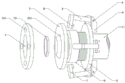
FIG. 1 is a schematic perspective view of a flange of the present invention for easy assembly and disassembly;
FIG. 2 is a schematic structural view of a pressing mechanism of a flange convenient to disassemble and assemble according to the present invention;
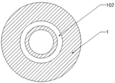
fig. 3 is a schematic side view of a first flange plate of the flange convenient to disassemble and assemble according to the present invention.
Illustration of the drawings:
1. a first flange piece; 101. a cylindrical groove; 102. a circular groove; 2. a second flange piece; 201. a conical ring; 3. a fixing ring; 4. hinging seat; 5. a pull rod; 6. a rotating shaft; 7. a connecting member; 8. positioning pins; 9. a pressurizing mechanism; 901. a sleeve; 902. a threaded barrel; 903. a jack; 10. a backing ring; 11. a pipeline.
Detailed Description
The technical solutions in the embodiments of the present invention will be clearly and completely described below with reference to the drawings in the embodiments of the present invention, and it is obvious that the described embodiments are only a part of the embodiments of the present invention, and not all of the embodiments. All other embodiments, which can be derived by a person skilled in the art from the embodiments given herein without making any creative effort, shall fall within the protection scope of the present invention.
Example 1
Referring to fig. 1-3, the flange comprises a first flange plate 1, a second flange plate 2 and a pipeline 11 fixedly connected with the second flange plate 2, a cylindrical groove 101 is formed on the side wall of the first flange plate 1 far away from the second flange plate 2, a positioning pin 8 is inserted in the cylindrical groove 101, the length of the positioning pin 8 is smaller than the depth of the cylindrical groove 101, a fixing ring 3 is sleeved on the pipeline 11, a hinged support 4 is fixedly connected on the side surface of the fixing ring 3 far away from the second flange plate 2, the hinged support 4 is hinged with a pull rod 5 through a rotating shaft 6, the rotating shaft 6 on the hinged support 4 is positioned outside the fixing ring 3, a connecting piece 7 is fixedly connected at the end of the pull rod 5, the positioning pin 8 is fixedly connected on the side surface of the connecting piece 7 connected with the pull rod 5, when the positioning pin 8 is inserted in the cylindrical groove 101, the pull rod 5 is parallel to the axial lead of the pipeline 11, a pressurizing mechanism, the pressurizing mechanism 9 mainly comprises a sleeve 901, a threaded cylinder 902 and a plug 903, wherein the sleeve 901 is provided with internal threads which are connected with the threaded cylinder 902 in a screwing way, and the threaded cylinder 902 is fixedly connected with the fixing ring 3.
Example 2
Referring to fig. 1-3, the side wall of the second flange plate 2 close to the first flange plate 1 is provided with a conical ring 201, the side wall of the first flange plate 1 close to the second flange plate 2 is provided with an annular groove 102, the conical ring 201 is inserted into the annular groove 102, a backing ring 10 is arranged in the annular groove 102, the conical ring 201 abuts against the side wall of the backing ring 10, and when the first flange plate 1 and the second flange plate 2 are in press fit, the pipeline 11 is connected and has good sealing performance.
The working principle is as follows: the known flange is a connecting component for the end of a pipeline 11, the pipeline 11 is in sealed connection through the fixed connection of a first flange piece 1 and a second flange piece 2, when the flange is used, a fixing ring 3 and a pressurizing mechanism 9 are sleeved on the pipeline 11, a threaded cylinder 902 and the fixing ring 3 are fixed in a spot welding mode, a sleeve 901 is adjusted to enable a positioning pin 8 to be inserted into a cylindrical groove 101, a tool for screwing the sleeve 901 is inserted into a jack 903, the pressurizing mechanism 9 pushes the fixing ring 3, the first flange piece 1 and the second flange piece 2 are tightly clamped under the pulling of a pull rod 5 and a connecting piece 7, a conical ring 201 abuts against a backing ring 10 in an annular groove 102, and the pipeline 11 is sealed and connected.
The above description is only for the preferred embodiment of the present invention, but the scope of the present invention is not limited thereto, and any person skilled in the art should be considered to be within the technical scope of the present invention, and the technical solutions and the inventive concepts thereof according to the present invention should be equivalent or changed within the scope of the present invention.
Claims (6)
1. A flange convenient to disassemble and assemble comprises a first flange piece (1), a second flange piece (2) and a pipeline (11) fixedly connected with the second flange piece (2), and is characterized in that the first flange piece (1) is provided with a cylindrical groove (101) on the side wall far away from the second flange piece (2), the pipeline (11) is sleeved with a fixing ring (3), the side surface far away from the second flange piece (2) of the fixing ring (3) is fixedly connected with a hinged support (4), the hinged support (4) is hinged with a pull rod (5) through a rotating shaft (6), the end part of the pull rod (5) is fixedly connected with a connecting piece (7), the side surface connected with the pull rod (5) of the connecting piece (7) is fixedly connected with a positioning pin (8), a pressurizing mechanism (9) sleeved on the pipeline (11) is arranged between the fixing ring (3) and the second flange piece (2), the pressurizing mechanism (9) mainly comprises a sleeve (901), a threaded cylinder (902) and a plug hole (903).
2. A flange convenient for dismounting and mounting according to claim 1, characterized in that the side wall of the second flange plate (2) close to the first flange plate (1) is provided with a conical ring (201), the side wall of the first flange plate (1) close to the second flange plate (2) is provided with an annular groove (102), and the conical ring (201) is inserted into the annular groove (102).
3. A flange easy to dismount and mount according to claim 2, characterized in that the ring groove (102) is provided with a backing ring (10) therein.
4. A flange convenient for dismounting according to claim 1, characterized in that said sleeve (901) has internal threads to be screwed with a threaded cylinder (902), and said threaded cylinder (902) is fixedly connected with a fixed ring (3).
5. A flange convenient for dismounting according to claim 1, characterized in that the positioning pin (8) is inserted in the cylindrical groove (101) of the first flange plate (1) and the length of the positioning pin (8) is smaller than the depth of the cylindrical groove (101).
6. A flange easy to disassemble and assemble according to claim 1, wherein the rotating shaft (6) on the hinge base (4) is positioned outside the fixed ring (3), and the pull rod (5) is parallel to the axis of the pipeline (11) when the positioning pin (8) is inserted into the cylindrical groove (101).
Priority Applications (1)
| Application Number | Priority Date | Filing Date | Title |
|---|---|---|---|
| CN202010747935.1A CN111853393A (en) | 2020-07-30 | 2020-07-30 | Flange convenient to disassemble and assemble |
Applications Claiming Priority (1)
| Application Number | Priority Date | Filing Date | Title |
|---|---|---|---|
| CN202010747935.1A CN111853393A (en) | 2020-07-30 | 2020-07-30 | Flange convenient to disassemble and assemble |
Publications (1)
| Publication Number | Publication Date |
|---|---|
| CN111853393A true CN111853393A (en) | 2020-10-30 |
Family
ID=72946162
Family Applications (1)
| Application Number | Title | Priority Date | Filing Date |
|---|---|---|---|
| CN202010747935.1A Pending CN111853393A (en) | 2020-07-30 | 2020-07-30 | Flange convenient to disassemble and assemble |
Country Status (1)
| Country | Link |
|---|---|
| CN (1) | CN111853393A (en) |
Cited By (2)
| Publication number | Priority date | Publication date | Assignee | Title |
|---|---|---|---|---|
| CN112229695A (en) * | 2020-12-11 | 2021-01-15 | 南京艾科赛棱特环保科技有限公司 | Heavy metal detecting system for food processing |
| CN113752187A (en) * | 2021-09-23 | 2021-12-07 | 莱芜钢铁集团建筑安装工程有限公司 | Steelmaking converter flue strutting arrangement |
Citations (6)
| Publication number | Priority date | Publication date | Assignee | Title |
|---|---|---|---|---|
| GB2010429A (en) * | 1977-12-19 | 1979-06-27 | Pusnes Mek Verksted | Flanged Pipe Couplings |
| CN2524047Y (en) * | 2002-01-11 | 2002-12-04 | 河北省枣强华联液化气配件有限公司 | Flanged connectors |
| KR20080026750A (en) * | 2006-09-21 | 2008-03-26 | 허차순 | Pipe connecter having a complex water sealing structure |
| CN204345130U (en) * | 2014-11-21 | 2015-05-20 | 中国石油天然气股份有限公司 | The seal arrangement of tubing head and valve |
| CN205534735U (en) * | 2016-04-14 | 2016-08-31 | 常州市武进第二法兰锻造有限公司 | Canned type flange |
| CN210291066U (en) * | 2019-06-25 | 2020-04-10 | 朱俱君 | Pipe fitting flange convenient to installation |
-
2020
- 2020-07-30 CN CN202010747935.1A patent/CN111853393A/en active Pending
Patent Citations (6)
| Publication number | Priority date | Publication date | Assignee | Title |
|---|---|---|---|---|
| GB2010429A (en) * | 1977-12-19 | 1979-06-27 | Pusnes Mek Verksted | Flanged Pipe Couplings |
| CN2524047Y (en) * | 2002-01-11 | 2002-12-04 | 河北省枣强华联液化气配件有限公司 | Flanged connectors |
| KR20080026750A (en) * | 2006-09-21 | 2008-03-26 | 허차순 | Pipe connecter having a complex water sealing structure |
| CN204345130U (en) * | 2014-11-21 | 2015-05-20 | 中国石油天然气股份有限公司 | The seal arrangement of tubing head and valve |
| CN205534735U (en) * | 2016-04-14 | 2016-08-31 | 常州市武进第二法兰锻造有限公司 | Canned type flange |
| CN210291066U (en) * | 2019-06-25 | 2020-04-10 | 朱俱君 | Pipe fitting flange convenient to installation |
Cited By (4)
| Publication number | Priority date | Publication date | Assignee | Title |
|---|---|---|---|---|
| CN112229695A (en) * | 2020-12-11 | 2021-01-15 | 南京艾科赛棱特环保科技有限公司 | Heavy metal detecting system for food processing |
| CN112229695B (en) * | 2020-12-11 | 2021-05-28 | 山东中捷检测技术有限公司 | Heavy metal detecting system for food processing |
| CN113752187A (en) * | 2021-09-23 | 2021-12-07 | 莱芜钢铁集团建筑安装工程有限公司 | Steelmaking converter flue strutting arrangement |
| CN113752187B (en) * | 2021-09-23 | 2022-10-18 | 莱芜钢铁集团建筑安装工程有限公司 | Steelmaking converter flue strutting arrangement |
Similar Documents
| Publication | Publication Date | Title |
|---|---|---|
| CN111853393A (en) | Flange convenient to disassemble and assemble | |
| CN106180776B (en) | A kind of thin-wall flange precision turning clamp | |
| CN211661567U (en) | Machining clamp for three-way part | |
| CN212704437U (en) | Expansion sleeve clamp | |
| CN210817555U (en) | End face hole machining tool for steam turbine bearing box | |
| CN210196224U (en) | Insert type multifunctional bushing | |
| CN108655772B (en) | Turning clamp for gas turbine rectifying housing | |
| CN110091200B (en) | Hole machining clamp for air inlet pipe | |
| CN208801302U (en) | A kind of small bearing installing tool of instrument and meter | |
| CN208132475U (en) | A kind of vehicle spherical surface fixture of whole world face differential casing | |
| CN215318450U (en) | A assembly and disassembly tools for oil blanket on bent axle | |
| CN211681010U (en) | Special fixture for sprocket thin-wall part precision boring process | |
| CN210997366U (en) | Opening rubber bushing press fitting device | |
| CN214814990U (en) | Positioning and supporting clamp for machining small holes of turbine flow guide disc | |
| CN212887393U (en) | Press mounting tool for pump transmission shaft | |
| CN205817657U (en) | A kind of cubing clamping device and comprise the cubing of this cubing clamping device | |
| CN214274163U (en) | Nut buckle suitable for different threads | |
| CN213703277U (en) | Device for assembling and disassembling thread connection | |
| CN219747771U (en) | Hydraulic pump tail shaft graphite ring seal assembly fixture | |
| CN209762485U (en) | Clamp hoop | |
| CN214222335U (en) | Axial crimping connector | |
| CN220354727U (en) | Alumina ceramic composite connecting pipe joint | |
| CN212145342U (en) | End face pressing rotary clamp | |
| CN219027380U (en) | Turbine rotor assembly tool | |
| CN214788327U (en) | Thin hydraulic oil cylinder |
Legal Events
| Date | Code | Title | Description |
|---|---|---|---|
| PB01 | Publication | ||
| PB01 | Publication | ||
| SE01 | Entry into force of request for substantive examination | ||
| SE01 | Entry into force of request for substantive examination | ||
| RJ01 | Rejection of invention patent application after publication |
Application publication date: 20201030 |
|
| RJ01 | Rejection of invention patent application after publication |