CN111853168A - Built-in planetary gear reducer - Google Patents
Built-in planetary gear reducer Download PDFInfo
- Publication number
- CN111853168A CN111853168A CN202010881790.4A CN202010881790A CN111853168A CN 111853168 A CN111853168 A CN 111853168A CN 202010881790 A CN202010881790 A CN 202010881790A CN 111853168 A CN111853168 A CN 111853168A
- Authority
- CN
- China
- Prior art keywords
- gear
- eccentric shaft
- cosine curve
- rear end
- end cover
- Prior art date
- Legal status (The legal status is an assumption and is not a legal conclusion. Google has not performed a legal analysis and makes no representation as to the accuracy of the status listed.)
- Pending
Links
Images


Classifications
-
- F—MECHANICAL ENGINEERING; LIGHTING; HEATING; WEAPONS; BLASTING
- F16—ENGINEERING ELEMENTS AND UNITS; GENERAL MEASURES FOR PRODUCING AND MAINTAINING EFFECTIVE FUNCTIONING OF MACHINES OR INSTALLATIONS; THERMAL INSULATION IN GENERAL
- F16H—GEARING
- F16H1/00—Toothed gearings for conveying rotary motion
- F16H1/28—Toothed gearings for conveying rotary motion with gears having orbital motion
- F16H1/32—Toothed gearings for conveying rotary motion with gears having orbital motion in which the central axis of the gearing lies inside the periphery of an orbital gear
-
- F—MECHANICAL ENGINEERING; LIGHTING; HEATING; WEAPONS; BLASTING
- F16—ENGINEERING ELEMENTS AND UNITS; GENERAL MEASURES FOR PRODUCING AND MAINTAINING EFFECTIVE FUNCTIONING OF MACHINES OR INSTALLATIONS; THERMAL INSULATION IN GENERAL
- F16H—GEARING
- F16H55/00—Elements with teeth or friction surfaces for conveying motion; Worms, pulleys or sheaves for gearing mechanisms
- F16H55/02—Toothed members; Worms
- F16H55/08—Profiling
- F16H55/088—Profiling with corrections on tip or foot of the teeth, e.g. addendum relief for better approach contact
-
- F—MECHANICAL ENGINEERING; LIGHTING; HEATING; WEAPONS; BLASTING
- F16—ENGINEERING ELEMENTS AND UNITS; GENERAL MEASURES FOR PRODUCING AND MAINTAINING EFFECTIVE FUNCTIONING OF MACHINES OR INSTALLATIONS; THERMAL INSULATION IN GENERAL
- F16H—GEARING
- F16H55/00—Elements with teeth or friction surfaces for conveying motion; Worms, pulleys or sheaves for gearing mechanisms
- F16H55/02—Toothed members; Worms
- F16H55/17—Toothed wheels
-
- F—MECHANICAL ENGINEERING; LIGHTING; HEATING; WEAPONS; BLASTING
- F16—ENGINEERING ELEMENTS AND UNITS; GENERAL MEASURES FOR PRODUCING AND MAINTAINING EFFECTIVE FUNCTIONING OF MACHINES OR INSTALLATIONS; THERMAL INSULATION IN GENERAL
- F16H—GEARING
- F16H57/00—General details of gearing
- F16H57/02—Gearboxes; Mounting gearing therein
- F16H57/021—Shaft support structures, e.g. partition walls, bearing eyes, casing walls or covers with bearings
-
- F—MECHANICAL ENGINEERING; LIGHTING; HEATING; WEAPONS; BLASTING
- F16—ENGINEERING ELEMENTS AND UNITS; GENERAL MEASURES FOR PRODUCING AND MAINTAINING EFFECTIVE FUNCTIONING OF MACHINES OR INSTALLATIONS; THERMAL INSULATION IN GENERAL
- F16H—GEARING
- F16H57/00—General details of gearing
- F16H57/02—Gearboxes; Mounting gearing therein
- F16H57/023—Mounting or installation of gears or shafts in the gearboxes, e.g. methods or means for assembly
-
- F—MECHANICAL ENGINEERING; LIGHTING; HEATING; WEAPONS; BLASTING
- F16—ENGINEERING ELEMENTS AND UNITS; GENERAL MEASURES FOR PRODUCING AND MAINTAINING EFFECTIVE FUNCTIONING OF MACHINES OR INSTALLATIONS; THERMAL INSULATION IN GENERAL
- F16H—GEARING
- F16H57/00—General details of gearing
- F16H57/08—General details of gearing of gearings with members having orbital motion
-
- F—MECHANICAL ENGINEERING; LIGHTING; HEATING; WEAPONS; BLASTING
- F16—ENGINEERING ELEMENTS AND UNITS; GENERAL MEASURES FOR PRODUCING AND MAINTAINING EFFECTIVE FUNCTIONING OF MACHINES OR INSTALLATIONS; THERMAL INSULATION IN GENERAL
- F16H—GEARING
- F16H1/00—Toothed gearings for conveying rotary motion
- F16H1/28—Toothed gearings for conveying rotary motion with gears having orbital motion
- F16H1/32—Toothed gearings for conveying rotary motion with gears having orbital motion in which the central axis of the gearing lies inside the periphery of an orbital gear
- F16H2001/323—Toothed gearings for conveying rotary motion with gears having orbital motion in which the central axis of the gearing lies inside the periphery of an orbital gear comprising eccentric crankshafts driving or driven by a gearing
-
- F—MECHANICAL ENGINEERING; LIGHTING; HEATING; WEAPONS; BLASTING
- F16—ENGINEERING ELEMENTS AND UNITS; GENERAL MEASURES FOR PRODUCING AND MAINTAINING EFFECTIVE FUNCTIONING OF MACHINES OR INSTALLATIONS; THERMAL INSULATION IN GENERAL
- F16H—GEARING
- F16H1/00—Toothed gearings for conveying rotary motion
- F16H1/28—Toothed gearings for conveying rotary motion with gears having orbital motion
- F16H1/32—Toothed gearings for conveying rotary motion with gears having orbital motion in which the central axis of the gearing lies inside the periphery of an orbital gear
- F16H2001/327—Toothed gearings for conveying rotary motion with gears having orbital motion in which the central axis of the gearing lies inside the periphery of an orbital gear with orbital gear sets comprising an internally toothed ring gear
-
- F—MECHANICAL ENGINEERING; LIGHTING; HEATING; WEAPONS; BLASTING
- F16—ENGINEERING ELEMENTS AND UNITS; GENERAL MEASURES FOR PRODUCING AND MAINTAINING EFFECTIVE FUNCTIONING OF MACHINES OR INSTALLATIONS; THERMAL INSULATION IN GENERAL
- F16H—GEARING
- F16H55/00—Elements with teeth or friction surfaces for conveying motion; Worms, pulleys or sheaves for gearing mechanisms
- F16H55/02—Toothed members; Worms
- F16H55/08—Profiling
- F16H2055/0866—Profiles for improving radial engagement of gears, e.g. chamfers on the tips of the teeth
Abstract
The invention belongs to the technical field of engineering machinery, and discloses a built-in planetary gear reducer which comprises a shell, a rear end cover, a right outer gear, an upper eccentric shaft, a power input shaft and an output disc, wherein the power input shaft is connected with the output disc; the left side of the eccentric shaft gear 41 of the upper eccentric shaft 4 is provided with a gear which is the same as the right external gear, the gear is a left external gear, the left external gear and the right external gear are arranged on the left side and the right side of the eccentric shaft gear, the power output is more balanced, the phenomenon of unbalanced acting force of a power input gear part is reduced, and the purpose of the invention can be realized.
Description
Technical Field
The invention belongs to the technical field of engineering machinery, and relates to a speed reducer, in particular to a built-in planetary gear speed reducer.
Background
An RV reducer (a planetary cycloidal pin gear reducer) is a relatively precise transmission machine. Is widely applied to robots and automatic production lines of various industries. The existing speed reducer usually adopts a mode of one group of planetary transmission gears and one group of cycloid gears or one group of cycloid pin gears for transmission to realize speed reduction. The transmission of a group of planetary transmission gears and a group of cycloid gears or a group of cycloid pin gears has the defect of uneven stress of a power input gear shaft, so that the operation is not stable; the parts in the speed reducer are easy to damage, the service life of the whole speed reducer is influenced, the installation requirements cannot be met, and in addition, the use effect of the whole speed reducer is also influenced due to the reason set in the process.
Disclosure of Invention
The invention aims to provide a built-in planetary gear reducer which is stable in operation, not easy to damage each part and long in service life.
The technical scheme is that the built-in planetary gear reducer comprises a shell, a rear end cover, a right outer gear, an upper eccentric shaft, a power input shaft and an output disc, wherein the power input shaft is connected with the output disc;
the shell is provided with shell internal teeth on the inner side of the shell and first angular contact ball bearing raceways on two sides of the shell;
the rear end cover is provided with a second angular contact ball bearing raceway and a rear end cover bearing hole arranged on one side of the center of the rear end cover;
the right outer gear is provided with a right outer gear and a right outer gear bearing hole arranged on one side of the center of the right outer gear;
the upper eccentric shaft is provided with an upper eccentric shaft gear in the middle, a right eccentric shaft part on the right side of the eccentric shaft gear, a right positive shaft part on the right side of the right eccentric shaft part and a left positive shaft part on the left side of the eccentric shaft gear;
the power input shaft comprises a power input gear shaft body and a power input tooth part;
the output disc comprises a hexagonal contact ball bearing raceway and an output disc bearing hole arranged on one side of the center of the output disc;
the power input shaft is arranged in the shell, the power input tooth part is meshed with the eccentric shaft gear, the right eccentric shaft part is arranged in the right external gear bearing hole in a matched mode, the right positive shaft part is arranged in the rear end cover bearing hole in a matched mode, and the left positive shaft part is arranged in the output disc bearing hole in a matched mode; the right external teeth are partially meshed with the internal teeth of the shell;
the rear end cover is fixedly connected with the output disc through bolts;
the power input gear shaft rotates to drive the eccentric shaft gear to rotate and drive the right external gear to rotate and revolve, and the output disc outputs at a lower speed;
the method is characterized in that:
a left eccentric shaft part is also arranged between the left side of the eccentric shaft gear of the upper eccentric shaft and the left positive shaft part, and the left eccentric shaft further comprises a left outer gear which is provided with a left outer gear and a left outer gear bearing hole arranged at one side of the center of the left outer gear; the left eccentric shaft part is arranged in a bearing hole of the left outer gear, and the left outer gear is partially meshed with the inner gear of the shell.
The power input is transmitted from the eccentric shaft gear to the shell through the left outer gear and the right outer gear (outer gears) and acts on the inner teeth of the shell, and because the right positive shaft part is installed in the bearing hole of the rear end cover in a matching way, the left positive shaft part is installed in the bearing hole of the output disc in a matching way; the rear end cover and the output disc are driven to form an integral body to output power outwards.
The invention has the beneficial effects that:
the eccentric shaft is provided with the two outer gears which are the left outer gear and the right outer gear respectively, and the two outer gears are arranged on two sides of the eccentric shaft gear of the eccentric shaft, so that the eccentric shaft has the advantage of stable operation, and the purpose of prolonging the service life can be achieved.
The eccentric shaft also comprises a lower eccentric shaft, and has the advantage of more stable power transmission;
the eccentric shaft has the advantages that the eccentric distances of the center line of the right eccentric shaft part and the center line of the left eccentric shaft part relative to the center line of the gear are equal and form 180 degrees with each other, and the power transmission is more stable.
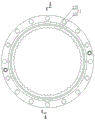
Fig. 1 is a schematic view of a housing of the present invention.
Fig. 2 is a schematic sectional view taken along the direction a-a in fig. 1.
FIG. 3 is a schematic view of the rear end cap of the present invention.
Fig. 4 is a schematic diagram of the right external gear (left external gear) of the present invention.
Fig. 5 is a schematic view of the upper eccentric shaft (lower eccentric shaft) of the present invention.
Fig. 6 is a schematic diagram of an output disk of the present invention.
FIG. 7 is a side schematic view of a speed reducer of the present invention.
Fig. 8 is a schematic cross-sectional view (a section in the direction B-B in fig. 7) of the decelerator of the present invention.
Fig. 9 is a schematic cross-sectional view taken along line C-C in fig. 8.
Fig. 10 is a schematic cross-sectional view taken along the direction D-C in fig. 8.
Fig. 11 is a schematic sectional view taken along the direction E-E in fig. 8.
Fig. 12 is a schematic view of the shell profile configuration of the present invention.
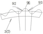
Fig. 13 is a schematic diagram of the tooth profile structure of the right and/or left external gear.
Wherein: 1. the bearing device comprises a shell 11, shell internal teeth 12, a first angular contact ball bearing raceway 2, a rear end cover 21, a second angular contact ball bearing raceway 22, a rear end cover bearing hole 3, a right external gear 31, a right external gear 32, a right external gear bearing hole 4, an upper eccentric shaft 41, an eccentric shaft gear 42, a right eccentric shaft portion 43, a right positive shaft portion 44, a left positive shaft portion 45, a left eccentric shaft portion 5, a power input shaft 51, a power input gear shaft body 52, a power input tooth portion 6, an output disc 61, a hexagonal contact ball bearing raceway 62, an output disc bearing hole 7, a left external gear 71, a left external gear 72, a left external gear bearing hole 8, a lower eccentric shaft 81, an eccentric shaft gear 82, a right eccentric shaft portion 83, a right positive shaft portion 84, a left positive shaft portion 85, a left eccentric shaft portion 91, a first cosine curve segment 92, a second cosine curve segment 93, A third cosine curve section 94, a first minor arc 95, a second minor arc 96, a third minor arc 100, a bolt.
Detailed Description
The invention is further described below with reference to the accompanying drawings.
The built-in planetary gear reducer comprises a shell 1, a rear end cover 2, a right external gear 3, an upper eccentric shaft 4, a power input shaft 5 and an output disc 6;
the shell 1 is provided with shell internal teeth 11 on the inner side of the shell and first angular contact ball bearing raceways 12 on two sides of the shell;
the rear end cover 2 is provided with a second angular contact ball bearing raceway 21 and a rear end cover bearing hole 22 arranged on one side of the center of the rear end cover;
the right outer gear 3 is provided with a right outer gear 31 and a right outer gear bearing hole 32 arranged on one side of the center of the right outer gear;
the upper eccentric shaft 4 has an upper eccentric shaft gear 41 in the middle, a right eccentric shaft part 42 on the right side of the eccentric shaft gear, a right positive shaft part 43 on the right side of the right eccentric shaft part, and a left positive shaft part 44 on the left side of the eccentric shaft gear;
the power input shaft 5 comprises a power input gear shaft body 51 and a power input tooth part 52;
the output disc 6 comprises a hexagonal contact ball bearing raceway 61 and an output disc bearing hole 62 arranged on one side of the center of the output disc;
the power input shaft 5 is arranged in the shell, the power input tooth part 52 is meshed with the eccentric shaft gear 41, the right eccentric shaft part 42 is arranged in the right external gear bearing hole 32 in a matching way, the right positive shaft part 43 is arranged in the rear end cover bearing hole 22 in a matching way, and the left positive shaft part 44 is arranged in the output disc bearing hole 62 in a matching way; the right external teeth 31 partially mesh with the housing internal teeth 11;
the rear end cover 2 is fixedly connected with the output disc 6 through bolts 100;
the power input gear 5 rotates to drive the eccentric shaft gear 41 to rotate and drive the right external gear 3 to rotate and revolve, and the output disc outputs at a lower speed;
the method is characterized in that:
a left eccentric shaft part 45 is arranged between the left side of the eccentric shaft gear 41 of the upper eccentric shaft 4 and the left positive shaft part 44, and the left eccentric shaft part also comprises a left external gear 7 which is provided with a left external gear 71 and a left external gear bearing hole 72 arranged at one side of the center of the left external gear; the left off-axis portion 45 is mounted in a left outer gear bearing hole 72, and the left outer gear 72 partially engages the housing inner gear 11.
The power input is transmitted from the eccentric shaft gear to the shell through the left external gear and the right external gear (external gears) and acts on the internal teeth of the shell, and because the right positive shaft part 43 is arranged in the rear end cover bearing hole 22 in a matching mode, the left positive shaft part 44 is arranged in the output disc bearing hole 62 in a matching mode; the rear end cover and the output disc are driven to form an integral body to output power outwards.
That is, a gear identical to the right external gear is installed on the left side of the eccentric shaft gear 41 of the upper eccentric shaft 4, the gear is the left external gear, the left external gear and the right external gear are installed on the left side and the right side of the eccentric shaft gear, the power output is more balanced, the phenomenon of unbalanced acting force of the power input tooth part is reduced, and the purpose of the invention can be realized.
The built-in planetary structure provided by the invention changes the stress mode of the upper eccentric shaft, so that the stress of the upper eccentric shaft is more reasonable and uniform, the torsional rigidity and the bearing capacity of the upper eccentric shaft are improved, and the force balance of the upper eccentric shaft is facilitated.
Further, it comprises a lower eccentric shaft 8 having a central eccentric shaft gear 81 and a right eccentric shaft portion 82 on the right side of the lower eccentric shaft gear, a right positive shaft portion 83 on the right side of the right eccentric shaft portion, a left eccentric shaft portion 85 on the left side of the eccentric shaft gear, a left positive shaft portion 84 on the left side of the left eccentric shaft portion 85; namely, the structure is the same as that of the upper eccentric shaft;
the rear end cover 2 is provided with two rear end cover bearing holes which are symmetrically arranged with the center of the rear end cover as the center;
the two right outer gear bearing holes of the right outer gear are symmetrically arranged by taking the center of the right outer gear as a center;
the two left outer gear bearing holes of the left outer gear are symmetrically arranged by taking the center of the left outer gear as a center;
the output disc 6 has two output disc bearing holes which are symmetrically arranged by taking the center of the output disc as the center;
the right eccentric shaft part of the lower eccentric shaft is arranged in the other right external gear bearing hole, the right positive shaft part is arranged in the other rear end cover bearing hole, the left eccentric shaft part is arranged in the other left external gear bearing hole of the left external gear, the left positive shaft part is arranged in the other output disc bearing hole,
the power input tooth portion 52 engages the eccentric shaft gear 41 of the lower eccentric shaft.
The invention has the advantage of more stable power transmission.
The inner gear of the shell is internally meshed with the two outer gears, and meshing points are two and form an angle of 180 degrees with each other; and the gears of two eccentric gear shafts (an upper eccentric shaft and a lower eccentric shaft) of the power input tooth part are externally engaged, an inner gear of the shell is fixed, when the power input shaft inputs power, the two eccentric gear shafts simultaneously rotate, and the eccentric parts of the two eccentric gear shafts drive the two outer gears (a right outer gear and a left outer gear) and the inner gear of the shell to perform small tooth difference rotation motion to realize two-stage speed reduction. The invention only realizes the speed reduction purpose through two sets of meshing gear pairs and gear eccentric shafts, thereby having the advantages of simple structure, short transmission chain, stable transmission, smaller volume and the like; because of adopting the gear eccentric shaft structure, the eccentric shaft which is a spline shaft relative to one end is designed to be a structure with a relatively fixed eccentric position, and the processing is easy to realize; the processing of the spline hole of the planetary gear and the assembling and adjusting links of the planetary gear and the spline shaft are omitted, and the assembling error is reduced, so that the precision and the stability of the speed reducer are improved.
Furthermore, the eccentricity of the central line of the right eccentric shaft part and the central line of the left eccentric shaft part on the eccentric shaft relative to the central line of the gear is equal and 180 degrees is formed between the central lines.
As a further improvement of the invention, adjacent internal teeth of the gear in the shell close to the tooth crest are internal tooth main body profiles, the internal tooth main body profiles are a section of cosine curve, and the cosine curve section at one end is a first cosine curve section 91; the adjacent outer teeth of the outer gear approach the outer tooth main body profile of the tooth valley, the outer tooth main body profile is a cosine curve section, and the cosine curve section is a second cosine curve section 92 and a third cosine curve section 93.
As a further improvement of the invention, the single tooth profile of the internal gear is formed by connecting a first minor arc 94, a first cosine curve segment 91 and a second minor arc 95 in sequence; the first minor arc is smoothly connected with the first cosine curve section, and the second minor arc is smoothly connected with the first cosine curve section; the circle centers of circles where the first minor arc and the second minor arc are located are concentric with a reference circle of the composite cosine internal gear, and the radiuses of the first minor arc and the second minor arc are equal;
the first cosine curve section is a cosine curve section formed by taking a reference circle of the internal gear as a transverse axis of a coordinate system;
the single tooth profile of the external gear is formed by sequentially connecting a second cosine curve section 92, a third minor arc 96 and a third cosine curve section 93; the second cosine curve section is smoothly connected with a third minor arc, and the third minor arc is smoothly connected with the third cosine curve section; the center of the circle where the third minor arc is located is concentric with the reference circle of the external gear, and the radius of the third minor arc is larger than that of the reference circle; the second cosine curve segment and the third cosine curve segment are cosine curve segments formed by taking a reference circle of the external gear as a horizontal axis of a coordinate system.
According to the group of composite cosine internal gear pairs provided by the invention, the composite cosine external gear and the composite cosine internal gear are formed by smoothly connecting cosine curve segments and arcs of minor arcs, and the tooth root has larger thickness, high contact strength and strong bearing capacity; the number of teeth may be smaller; the internal teeth are completely engaged with the cosine curve section of the side surface of the external teeth, when the gear operates, the internal gear and the external gear are in continuous contact and basically roll, the transmission efficiency is high, and the power transmission is stable.
According to the set of compound cosine internal gear pair provided by the invention, the tooth top of the compound cosine external gear and the tooth root of the compound cosine internal gear are both formed by minor arcs, so that a certain gap is kept between the tooth root and the tooth top when the gear pair is meshed, and impact, friction and noise caused by the contact between the tooth root and the tooth top are avoided.
The tooth profile of the compound cosine internal gear pair provided by the invention has a complete mathematical model, the tooth profile structures of the compound cosine internal gear and the compound cosine external gear are simple, the tooth profile curves are consistent, the processing precision is easy to control, the processing difficulty of the gear is low, and the popularization and the application are facilitated.
The above description is only a preferred embodiment of the present invention, and should not be taken as limiting the invention in any way, and any person skilled in the art can make many changes or modifications to the equivalent embodiments without departing from the scope of the present invention.
Claims (5)
1. The built-in planetary gear reducer comprises a shell, a rear end cover, a right outer gear, an upper eccentric shaft, a power input shaft and an output disc;
the shell is provided with shell internal teeth on the inner side of the shell and first angular contact ball bearing raceways on two sides of the shell;
the rear end cover is provided with a second angular contact ball bearing raceway and a rear end cover bearing hole arranged on one side of the center of the rear end cover;
the right outer gear is provided with a right outer gear and a right outer gear bearing hole arranged on one side of the center of the right outer gear;
the upper eccentric shaft is provided with an upper eccentric shaft gear in the middle, a right eccentric shaft part on the right side of the eccentric shaft gear, a right positive shaft part on the right side of the right eccentric shaft part and a left positive shaft part on the left side of the eccentric shaft gear;
the power input shaft comprises a power input gear shaft body and a power input tooth part;
the output disc comprises a hexagonal contact ball bearing raceway and an output disc bearing hole arranged on one side of the center of the output disc;
the power input shaft is arranged in the shell, the power input tooth part is meshed with the eccentric shaft gear, the right eccentric shaft part is arranged in the right external gear bearing hole in a matched mode, the right positive shaft part is arranged in the rear end cover bearing hole in a matched mode, and the left positive shaft part is arranged in the output disc bearing hole in a matched mode; the right external teeth are partially meshed with the internal teeth of the shell;
the rear end cover is fixedly connected with the output disc through bolts;
the power input gear shaft rotates to drive the eccentric shaft gear to rotate and drive the right external gear to rotate and revolve, and the output disc outputs at a lower speed;
the method is characterized in that:
a left eccentric shaft part is also arranged between the left side of the eccentric shaft gear of the upper eccentric shaft and the left positive shaft part, and the left eccentric shaft further comprises a left outer gear which is provided with a left outer gear and a left outer gear bearing hole arranged at one side of the center of the left outer gear; the left eccentric shaft part is arranged in a bearing hole of the left outer gear, and the left outer gear is partially meshed with the inner gear of the shell.
The power input is transmitted from the eccentric shaft gear to the shell through the left outer gear and the right outer gear (outer gears) and acts on the inner teeth of the shell, and because the right positive shaft part is installed in the bearing hole of the rear end cover in a matching way, the left positive shaft part is installed in the bearing hole of the output disc in a matching way; the rear end cover and the output disc are driven to form an integral body to output power outwards.
2. The built-in planetary gear reducer according to claim 1, wherein: the eccentric shaft gear is arranged on the left side of the eccentric shaft gear, and the eccentric shaft gear is arranged on the right side of the eccentric shaft gear.
3. The built-in planetary gear reducer according to claim 2, wherein: the rear end cover bearing holes of the rear end cover are two, and the two rear end cover bearing holes are symmetrically arranged by taking the center of the rear end cover as a center;
the two right outer gear bearing holes of the right outer gear are symmetrically arranged by taking the center of the right outer gear as a center;
the two left outer gear bearing holes of the left outer gear are symmetrically arranged by taking the center of the left outer gear as a center;
the output disc comprises two output disc bearing holes which are symmetrically arranged by taking the center of the output disc as the center;
the right eccentric shaft part of the lower eccentric shaft is arranged in the other right external gear bearing hole, the right positive shaft part is arranged in the other rear end cover bearing hole, the left eccentric shaft part is arranged in the other left external gear bearing hole of the left external gear, the left positive shaft part is arranged in the other output disc bearing hole,
the power input tooth part is meshed with an eccentric shaft gear of the lower eccentric shaft.
The eccentric distances of the central line of the right eccentric shaft part and the central line of the left eccentric shaft part on the eccentric shaft relative to the central line of the gear are equal and form 180 degrees with each other.
4. The built-in planetary gear reducer according to claim 1, 2, or 3, wherein: the adjacent inner teeth of the gear in the shell are close to the tooth peak and are inner tooth main body profiles, the inner tooth main body profiles are a cosine curve section, and the cosine curve section at one end is a first cosine curve section; the external teeth adjacent to the external gear are close to the external tooth main body profile of the tooth valley, the external tooth main body profile is a cosine curve section, and the cosine curve section at the end is a second cosine curve section and a third cosine curve section.
5. The built-in planetary gear reducer according to claim 4, wherein: the single tooth profile of the internal gear is formed by sequentially connecting a first minor arc, a first cosine curve segment and a second minor arc; the first minor arc is smoothly connected with the first cosine curve section, and the second minor arc is smoothly connected with the first cosine curve section; the circle centers of circles where the first minor arc and the second minor arc are located are concentric with a reference circle of the composite cosine internal gear, and the radiuses of the first minor arc and the second minor arc are equal;
the first cosine curve section is a cosine curve section formed by taking a reference circle of the internal gear as a transverse axis of a coordinate system;
the single tooth profile of the external gear is formed by sequentially connecting a second cosine curve segment, a third minor arc and a third cosine curve segment; the second cosine curve section is smoothly connected with a third minor arc, and the third minor arc is smoothly connected with the third cosine curve section; the center of the circle where the third minor arc is located is concentric with the reference circle of the external gear, and the radius of the third minor arc is larger than that of the reference circle; the second cosine curve segment and the third cosine curve segment are cosine curve segments formed by taking a reference circle of the external gear as a horizontal axis of a coordinate system.
Priority Applications (1)
| Application Number | Priority Date | Filing Date | Title |
|---|---|---|---|
| CN202010881790.4A CN111853168A (en) | 2020-08-28 | 2020-08-28 | Built-in planetary gear reducer |
Applications Claiming Priority (1)
| Application Number | Priority Date | Filing Date | Title |
|---|---|---|---|
| CN202010881790.4A CN111853168A (en) | 2020-08-28 | 2020-08-28 | Built-in planetary gear reducer |
Publications (1)
| Publication Number | Publication Date |
|---|---|
| CN111853168A true CN111853168A (en) | 2020-10-30 |
Family
ID=72968216
Family Applications (1)
| Application Number | Title | Priority Date | Filing Date |
|---|---|---|---|
| CN202010881790.4A Pending CN111853168A (en) | 2020-08-28 | 2020-08-28 | Built-in planetary gear reducer |
Country Status (1)
| Country | Link |
|---|---|
| CN (1) | CN111853168A (en) |
Cited By (1)
| Publication number | Priority date | Publication date | Assignee | Title |
|---|---|---|---|---|
| CN112943892A (en) * | 2021-04-01 | 2021-06-11 | 河南睿辰机器人智能科技有限公司 | Transmission gear set and speed reducer |
-
2020
- 2020-08-28 CN CN202010881790.4A patent/CN111853168A/en active Pending
Cited By (1)
| Publication number | Priority date | Publication date | Assignee | Title |
|---|---|---|---|---|
| CN112943892A (en) * | 2021-04-01 | 2021-06-11 | 河南睿辰机器人智能科技有限公司 | Transmission gear set and speed reducer |
Similar Documents
| Publication | Publication Date | Title |
|---|---|---|
| CN107299970B (en) | Cycloidal steel ball speed reducer and application thereof in robot joint | |
| CN106352024B (en) | A kind of single eccentric short transmission chain retarder | |
| CN108488326A (en) | More bent axle cycloidal planetary gear speed reducers | |
| CN207093681U (en) | A kind of Cycloid Steel Ball Planetary Transmission mechanism and its joint of robot deceleration device | |
| CN108953541B (en) | RV speed reducer with ultralow reduction ratio | |
| US11835113B2 (en) | Gear pair and nutation reducer | |
| CN111022608A (en) | Two-stage sine hammer-shaped roller oscillating tooth speed reducer | |
| CN111853168A (en) | Built-in planetary gear reducer | |
| CN212455376U (en) | Built-in planetary gear reducer | |
| TW201305465A (en) | Transmission mechanism having eccentric cam assemblies | |
| CN104819253A (en) | Multi-crankshaft cycloid speed reducer | |
| CN112065950A (en) | High-contact-ratio internal gear and RV speed reducer taking same as transmission core | |
| CN112081879B (en) | One-tooth-difference cycloidal pin gear speed reducer | |
| CN214661788U (en) | Base cycloidal speed reducer for industrial heavy-duty robot | |
| CN114001125B (en) | Ultra-low speed ratio high-rigidity high-precision cycloidal pin gear planetary transmission speed reducer | |
| CN114877032A (en) | Large-torque high-rigidity robot joint reducer | |
| CN112178134B (en) | Large-scale high-rigidity impact-resistant precise speed reducer | |
| CN104832602A (en) | Power output device of multi-crankshaft cycloid speed reducer | |
| CN107882928A (en) | A kind of compound cycloidal reducer | |
| CN209925523U (en) | Planetary cycloidal speed reducer for light robot | |
| CN206175573U (en) | Single eccentric short driving chain reduction gear | |
| CN109139812A (en) | A kind of New-type cycloidal planetary reducer | |
| CN214661789U (en) | RV reducer adopting herringbone gear planetary reduction mechanism | |
| CN216789135U (en) | Cycloidal pin gear speed reducer | |
| CN210770059U (en) | RV speed reducer |
Legal Events
| Date | Code | Title | Description |
|---|---|---|---|
| PB01 | Publication | ||
| PB01 | Publication | ||
| SE01 | Entry into force of request for substantive examination | ||
| SE01 | Entry into force of request for substantive examination |