CN111829844A - Sampling method for metal fuse additive manufacturing sample - Google Patents
Sampling method for metal fuse additive manufacturing sample Download PDFInfo
- Publication number
- CN111829844A CN111829844A CN202010555262.XA CN202010555262A CN111829844A CN 111829844 A CN111829844 A CN 111829844A CN 202010555262 A CN202010555262 A CN 202010555262A CN 111829844 A CN111829844 A CN 111829844A
- Authority
- CN
- China
- Prior art keywords
- test piece
- sample
- blocks
- substrate
- additive manufacturing
- Prior art date
- Legal status (The legal status is an assumption and is not a legal conclusion. Google has not performed a legal analysis and makes no representation as to the accuracy of the status listed.)
- Pending
Links
Images


Classifications
-
- G—PHYSICS
- G01—MEASURING; TESTING
- G01N—INVESTIGATING OR ANALYSING MATERIALS BY DETERMINING THEIR CHEMICAL OR PHYSICAL PROPERTIES
- G01N1/00—Sampling; Preparing specimens for investigation
- G01N1/28—Preparing specimens for investigation including physical details of (bio-)chemical methods covered elsewhere, e.g. G01N33/50, C12Q
- G01N1/286—Preparing specimens for investigation including physical details of (bio-)chemical methods covered elsewhere, e.g. G01N33/50, C12Q involving mechanical work, e.g. chopping, disintegrating, compacting, homogenising
- G01N2001/2866—Grinding or homogeneising
-
- G—PHYSICS
- G01—MEASURING; TESTING
- G01N—INVESTIGATING OR ANALYSING MATERIALS BY DETERMINING THEIR CHEMICAL OR PHYSICAL PROPERTIES
- G01N1/00—Sampling; Preparing specimens for investigation
- G01N1/28—Preparing specimens for investigation including physical details of (bio-)chemical methods covered elsewhere, e.g. G01N33/50, C12Q
- G01N1/286—Preparing specimens for investigation including physical details of (bio-)chemical methods covered elsewhere, e.g. G01N33/50, C12Q involving mechanical work, e.g. chopping, disintegrating, compacting, homogenising
- G01N2001/2873—Cutting or cleaving
-
- G—PHYSICS
- G01—MEASURING; TESTING
- G01N—INVESTIGATING OR ANALYSING MATERIALS BY DETERMINING THEIR CHEMICAL OR PHYSICAL PROPERTIES
- G01N2203/00—Investigating strength properties of solid materials by application of mechanical stress
- G01N2203/02—Details not specific for a particular testing method
- G01N2203/026—Specifications of the specimen
- G01N2203/0298—Manufacturing or preparing specimens
Abstract
The invention belongs to the technical field of 3D printing, and particularly discloses a sampling method of a metal fuse additive manufacturing sample, which comprises the following steps: s1, preparing a substrate, wherein the material of the substrate is the same as that of the test piece; s2, printing a test piece on the substrate, wherein the test piece grows vertically; s3, removing the substrate from the test piece; s4, carrying out roughness processing on the surface of the test piece; s5, flaw detection is carried out on the test piece; s6, sampling distribution planning is carried out on the test piece, the test piece is cut according to the sampling distribution planning, and a plurality of required test pieces are cut; and S7, placing all the sample blocks on the substrate, laying out all the sample blocks, and detecting the performance of the laid sample blocks. The method can solve the problem that the prior art has no effective detection way and relevant standards, so that the performance of the printed part is difficult to determine.
Description
Technical Field
The invention belongs to the technical field of 3D printing, and particularly relates to a sampling method for a metal fuse additive manufacturing sample.
Background
As a subversive technology, metal additive manufacturing (3D printing) has a profound effect on the traditional process flow, production line, factory model, and industrial chain combination. The most prominent advantage of metal 3D printing is that the metal can be molded without a mold, and objects in any shape can be directly printed from designed three-dimensional graphic data.
Fuse additive manufacturing is a new technology, and currently, no effective detection way and relevant standards exist, so that the performance of printed parts is difficult to determine. There is an urgent need for a method for performing a comprehensive performance test on a test piece manufactured by metal fuse additive manufacturing.
Disclosure of Invention
The invention aims to provide a sampling method of a metal fuse additive manufacturing sample, which aims to solve the problem that the prior art has no effective detection way and relevant standards, so that the performance of a printed part is difficult to determine.
In order to achieve the purpose, the technical scheme of the invention is as follows: a sampling method of a metal fuse additive manufacturing sample comprises the following steps:
s1, preparing a substrate, wherein the material of the substrate is the same as that of the test piece;
s2, printing a test piece on the substrate, wherein the test piece grows vertically;
s3, removing the substrate from the test piece;
s4, carrying out roughness processing on the surface of the test piece;
s5, flaw detection is carried out on the test piece;
s6, sampling distribution planning is carried out on the test piece, the test piece is cut according to the sampling distribution planning, and a plurality of required test pieces are cut; the device comprises a bending sample block for measuring bending property, a horizontal tensile sample block and a vertical tensile sample block for measuring tensile property, an impact sample block for measuring impact property and a component sample block for measuring hardness and chemical components, wherein the bending sample block is used for cutting the front side and the rear side of a test piece;
and S7, placing all the sample blocks on the substrate, laying out all the sample blocks, and detecting the performance of the laid sample blocks.
Further, in step S2, the perpendicularity between the test piece and the substrate is 2mm or more.
Further, in step S2, the deformation of the printed test piece is measured, and if the deformation meets the requirement, step S3 is performed; and if the requirements are not met, the test piece is printed again.
Further, in step S3, the test piece needs to be subjected to edge cutting.
Further, in step S4, the surface roughness Ra of the test piece is less than or equal to 6.3 um.
Further, in step S4, the processing method adopted is: firstly, turning the test piece, and then grinding the test piece until the required roughness is achieved.
Further, in step S5, the flaw detection method used is radiographic inspection.
Further, in step S6, two bending sample pieces are provided on both front and rear sides of the test piece, three horizontal tensile sample pieces and three vertical tensile sample pieces are provided, three impact sample pieces are provided, and two component sample pieces are provided.
Further, in step S6, both sides of the horizontal tensile coupon and the vertical tensile coupon are wider than the middle portion; and a groove is formed in the middle of the bottom of the impact sample block.
Further, in step S7, four bending sample blocks and several other sample blocks are respectively located on both sides of the substrate, the four bending sample blocks are arranged side by side, and the longitudinal direction of the bending sample blocks is aligned with the longitudinal direction of the substrate; the vertical tensile test sample blocks are arranged on one side of the base plate side by side, and the length direction of the vertical tensile test sample blocks is perpendicular to the length direction of the base plate; the impact sample block and the horizontal tensile sample block are arranged side by side, and the length directions of the impact sample block and the horizontal tensile sample block are consistent with the length direction of the substrate; the composition sample blocks are arranged side by side and are positioned on one side, far away from the vertical tensile sample block, of the impact sample block.
The beneficial effects of this technical scheme lie in: firstly, different parts are adopted for detection on one test piece, and the utilization rate of the test piece is improved. And secondly, a plurality of sample blocks with the same detection function are adopted, so that the detection result is more accurate. The base plate is made of the same material as the test piece material, so that the requirement of test piece performance detection can be met. And fourthly, trimming the test piece to ensure that the surface of the test piece is free from defects. And fifthly, flaw detection treatment is carried out on the test piece, whether flaws such as cracks, air holes and impurities exist in the test piece is determined, and if the flaw detection result does not meet the requirement, the test piece needs to be reworked. Sixthly, printing the test pieces by adopting different printing modes, namely electric arc, electron beam, plasma, laser and composite fuse additive manufacturing, sampling and detecting the plurality of test pieces respectively, comparing the performance difference of the test pieces manufactured by different additives, and providing a theoretical basis for printing parts with complex structures. And seventhly, the sample blocks are arranged, and the detection accuracy of the sample blocks is ensured.
Drawings
FIG. 1 is a flow chart of a method for sampling a metal fuse additive manufacturing coupon in accordance with the present invention;
FIG. 2 is a front view of a substrate and a test piece;
FIG. 3 is a side view of a substrate and test piece;
FIG. 4 is a schematic view of a test piece without edges removed and without the substrate removed;
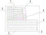
FIG. 5 is a schematic layout of a coupon;
FIG. 6 is a schematic view of a vertically stretched coupon and a horizontally stretched coupon;
figure 7 is a schematic view of an impact coupon.
Detailed Description
The following is further detailed by way of specific embodiments:
reference numerals in the drawings of the specification include: the test piece comprises a test piece 1, a base plate 2, a test piece front side bending test piece 3, a test piece rear side bending test piece 4, a vertical stretching test piece 5, a horizontal stretching test piece 6, an impact test piece 7 and a component test piece 8.
The technical solutions in the embodiments of the present invention will be clearly and completely described below with reference to the drawings in the embodiments of the present invention, and it is obvious that the described embodiments are only a part of the embodiments of the present invention, and not all of the embodiments. All other embodiments, which can be derived by a person skilled in the art from the embodiments given herein without making any creative effort, shall fall within the protection scope of the present invention.
The examples are substantially as shown in figures 1 to 7 of the accompanying drawings: a sampling method of a metal fuse additive manufacturing sample comprises the following steps:
s1, preparing five groups of substrates 2 and five groups of additive manufacturing (respectively arc, electron beam, plasma, laser and composite fuse additive manufacturing), wherein the material of each group of substrates 2 is the same as that of the corresponding test piece 1;
s2, printing a test piece 1 on the substrate 2, wherein the test piece 1 grows vertically, and the verticality between the test piece 1 and the corresponding substrate 2 is more than or equal to 2 mm; measuring the deformation of the printed test piece 1, and if the deformation meets the requirement, performing step S3; if the requirements are not met, the test piece 1 is printed again.
S3, removing the substrate 2 from the test piece 1 by adopting a linear cutting mode; because the edge of the test piece 1 generates obvious metal melting traces in the printing process, the test piece 1 needs to be trimmed before the sample is extracted, and the surface of the test piece is free of defects;
s4, carrying out roughness processing on the surface of the test piece 1 by adopting the following processing mode: turning the test piece 1, and grinding the test piece 1 until the surface roughness Ra of the test piece 1 is less than or equal to 6.3 um;
s5, performing radiographic inspection on the test piece 1 to determine whether the test piece 1 has defects such as cracks, air holes, impurities and the like, and if the inspection result does not meet the requirement, reworking the test piece 1;
s6, sampling distribution planning is carried out on each group of test pieces 1, each group of test pieces 1 are cut according to the sampling distribution planning, and 15 required test pieces are cut; the test piece comprises bending sample blocks (two bending sample blocks 3 at the front side and two bending sample blocks 4 at the rear side of the test piece) for measuring the bending performance, which are used for cutting the front side and the rear side of the test piece 1, a horizontal tensile sample block 6 and a vertical tensile sample block 5 (three blocks of the horizontal tensile sample block 6 and the vertical tensile sample block 5) for measuring the tensile performance, an impact sample block 7 for measuring the impact performance, and a component sample block 8 (three blocks of the impact sample block 7 and two blocks of the component sample block 8) for measuring the hardness and the chemical components, which are used for cutting the horizontal direction and the vertical direction of the test piece 1; the two sides of the horizontal tensile test sample block 6 and the vertical tensile test sample block 5 are wider than the middle part; the middle part of the bottom of the impact sample block 7 is provided with a groove;
s7, placing all the sample blocks on the substrate 2, laying out all the sample blocks, and detecting each performance of the laid sample blocks; the layout mode is as follows: the four bending sample blocks and other sample blocks are respectively positioned on two sides of the substrate 2, the four bending sample blocks are arranged side by side, and the length direction of the bending sample blocks is consistent with the length direction of the substrate 2; the vertical tensile test sample blocks 5 are arranged on the left upper side of the base plate 2 side by side, and the length direction of the vertical tensile test sample blocks 5 is vertical to the length direction of the base plate 2; the impact sample block 7 and the horizontal tensile sample block 6 are arranged side by side, and the length directions of the impact sample block 7 and the horizontal tensile sample block 6 are consistent with the length direction of the substrate 2; the component coupons 8 are arranged side by side and on the side of the impact coupon 7 remote from the vertical tensile coupon 5.
It is noted that, herein, relational terms such as first and second, and the like may be used solely to distinguish one entity or action from another entity or action without necessarily requiring or implying any actual such relationship or order between such entities or actions. Also, the terms "comprises," "comprising," or any other variation thereof, are intended to cover a non-exclusive inclusion, such that a process, method, article, or apparatus that comprises a list of elements does not include only those elements but may include other elements not expressly listed or inherent to such process, method, article, or apparatus.
The foregoing is merely an example of the present invention, and common general knowledge in the field of known specific structures and characteristics is not described herein in any greater extent than that known in the art at the filing date or prior to the priority date of the application, so that those skilled in the art can now appreciate that all of the above-described techniques in this field and have the ability to apply routine experimentation before this date can be combined with one or more of the present teachings to complete and implement the present invention, and that certain typical known structures or known methods do not pose any impediments to the implementation of the present invention by those skilled in the art. It should be noted that, for those skilled in the art, without departing from the structure of the present invention, several changes and modifications can be made, which should also be regarded as the protection scope of the present invention, and these will not affect the effect of the implementation of the present invention and the practicability of the patent. The scope of the claims of the present application shall be determined by the contents of the claims, and the description of the embodiments and the like in the specification shall be used to explain the contents of the claims.
Claims (10)
1. A sampling method of a metal fuse additive manufacturing sample is characterized in that: the method comprises the following steps:
s1, preparing a substrate, wherein the material of the substrate is the same as that of the test piece;
s2, printing a test piece on the substrate, wherein the test piece grows vertically;
s3, removing the substrate from the test piece;
s4, carrying out roughness processing on the surface of the test piece;
s5, flaw detection is carried out on the test piece;
s6, sampling distribution planning is carried out on the test piece, the test piece is cut according to the sampling distribution planning, and a plurality of required test pieces are cut; the device comprises a bending sample block for measuring bending property, a horizontal tensile sample block and a vertical tensile sample block for measuring tensile property, an impact sample block for measuring impact property and a component sample block for measuring hardness and chemical components, wherein the bending sample block is used for cutting the front side and the rear side of a test piece;
and S7, placing all the sample blocks on the substrate, laying out all the sample blocks, and detecting the performance of the laid sample blocks.
2. The sampling method of the metal fuse additive manufacturing sample according to claim 1, wherein: in step S2, the perpendicularity between the test piece and the substrate is 2mm or more.
3. The sampling method of the metal fuse additive manufacturing sample according to claim 1, wherein: in step S2, the deformation of the printed test piece is measured, and if the deformation meets the requirement, step S3 is performed; and if the requirements are not met, the test piece is printed again.
4. The sampling method of the metal fuse additive manufacturing sample according to claim 1, wherein: in step S3, the test piece also needs to be subjected to trimming processing.
5. The sampling method of the metal fuse additive manufacturing sample according to claim 1, wherein: in step S4, the surface roughness Ra of the test piece is less than or equal to 6.3 um.
6. The sampling method of the metal fuse additive manufacturing sample according to any one of the claims 1 or 5, wherein: in step S4, the processing method used is: firstly, turning the test piece, and then grinding the test piece until the required roughness is achieved.
7. The sampling method of the metal fuse additive manufacturing sample according to claim 1, wherein: and printing the test piece by adopting different printing modes, and sampling and detecting the plurality of test pieces respectively.
8. The sampling method of the metal fuse additive manufacturing sample according to claim 1, wherein: in step S6, two bending blocks are provided on the front and rear sides of the test piece, three horizontal tensile blocks and three vertical tensile blocks are provided, three impact blocks are provided, and two component blocks are provided.
9. The sampling method of the metal fuse additive manufacturing sample according to any one of claims 1 or 8, wherein: in step S6, both sides of the horizontal and vertical tensile coupons are wider than the middle portion; and a groove is formed in the middle of the bottom of the impact sample block.
10. The sampling method of the metal fuse additive manufacturing sample according to any one of the claim 8, wherein: in step S7, four bending sample blocks and several other sample blocks are respectively located on both sides of the substrate, the four bending sample blocks are arranged side by side, and the longitudinal direction of the bending sample blocks is aligned with the longitudinal direction of the substrate; the vertical tensile test sample blocks are arranged on one side of the base plate side by side, and the length direction of the vertical tensile test sample blocks is perpendicular to the length direction of the base plate; the impact sample block and the horizontal tensile sample block are arranged side by side, and the length directions of the impact sample block and the horizontal tensile sample block are consistent with the length direction of the substrate; the composition sample blocks are arranged side by side and are positioned on one side, far away from the vertical tensile sample block, of the impact sample block.
Priority Applications (1)
| Application Number | Priority Date | Filing Date | Title |
|---|---|---|---|
| CN202010555262.XA CN111829844A (en) | 2020-06-17 | 2020-06-17 | Sampling method for metal fuse additive manufacturing sample |
Applications Claiming Priority (1)
| Application Number | Priority Date | Filing Date | Title |
|---|---|---|---|
| CN202010555262.XA CN111829844A (en) | 2020-06-17 | 2020-06-17 | Sampling method for metal fuse additive manufacturing sample |
Publications (1)
| Publication Number | Publication Date |
|---|---|
| CN111829844A true CN111829844A (en) | 2020-10-27 |
Family
ID=72899212
Family Applications (1)
| Application Number | Title | Priority Date | Filing Date |
|---|---|---|---|
| CN202010555262.XA Pending CN111829844A (en) | 2020-06-17 | 2020-06-17 | Sampling method for metal fuse additive manufacturing sample |
Country Status (1)
| Country | Link |
|---|---|
| CN (1) | CN111829844A (en) |
Citations (2)
| Publication number | Priority date | Publication date | Assignee | Title |
|---|---|---|---|---|
| CN108507815A (en) * | 2018-03-27 | 2018-09-07 | 苏州热工研究院有限公司 | A kind of sampling method of nuclear steam generator primary side end socket demarcation strip quality inspection |
| CN110405318A (en) * | 2018-04-26 | 2019-11-05 | 天津大学 | A kind of CMT increasing material manufacturing method improving Tensile Properties of Aluminum Alloy |
-
2020
- 2020-06-17 CN CN202010555262.XA patent/CN111829844A/en active Pending
Patent Citations (2)
| Publication number | Priority date | Publication date | Assignee | Title |
|---|---|---|---|---|
| CN108507815A (en) * | 2018-03-27 | 2018-09-07 | 苏州热工研究院有限公司 | A kind of sampling method of nuclear steam generator primary side end socket demarcation strip quality inspection |
| CN110405318A (en) * | 2018-04-26 | 2019-11-05 | 天津大学 | A kind of CMT increasing material manufacturing method improving Tensile Properties of Aluminum Alloy |
Non-Patent Citations (1)
| Title |
|---|
| 程卫琴: "双金属交织结构等离子弧增材制造技术研究", 《中国优秀博硕士学位论文全文数据库硕士工程科技I辑》 * |
Similar Documents
| Publication | Publication Date | Title |
|---|---|---|
| CN106181260B (en) | A kind of processing method of chemical milling template | |
| KR101033144B1 (en) | Method and Apparatus for Cutting off Glass Panes from a Continuously Produced Glass Sheet | |
| CN103760177B (en) | A kind of method of carrying out defect analysis based on three-dimensional TEM sample | |
| Takino et al. | Cutting of polished single-crystal silicon by wire electrical discharge machining | |
| KR20120059355A (en) | Method for breaking brittle material substrate | |
| CN108536970A (en) | A kind of test method of aluminum alloy pretensioning plate internal residual stress | |
| CN112888173A (en) | Processing and forming process of PCB | |
| CN111829844A (en) | Sampling method for metal fuse additive manufacturing sample | |
| CN101474722A (en) | Laser cutting and positioning method for stamping parts and laser cutting and positioning device for stamping parts | |
| CN113533673A (en) | Metal foil strip internal stress distribution measuring method based on layer-by-layer thinning | |
| CN109238847B (en) | Three-dimensional measurement method for reduction rate of tensile thickness of metal material | |
| CN111721255A (en) | Flatness detection method and system | |
| Dobrzynski et al. | Experimental research of the effect of face milling strategy on the flatness deviations | |
| CN211626340U (en) | Online measuring device for large airplane thin-wall large-wall-plate parts | |
| CN206039266U (en) | Processing apparatus | |
| CN105619000B (en) | CNC machining part and manufacturing method thereof | |
| KR20190116357A (en) | Cu-Ni-Si copper alloy bath | |
| CN114878046A (en) | Method for measuring residual stress inside thick plate welding part | |
| Khomutskaya et al. | The method of automated evaluation of the deformation of the printed circuit board | |
| KR101459503B1 (en) | The method for manufacturing printed circuit board and the printed circuit board thereof | |
| CN109840372B (en) | Method, system, device and medium for determining optimal gap of metal sheet blanking | |
| CN110076920B (en) | Method for measuring wire mesh angle of multi-wire slicing machine | |
| CN219607898U (en) | Circuit board size detection jig | |
| CN207480121U (en) | It is a kind of to be convenient for the curved fixture for rushing sample processing of pinion steel | |
| CN108289373A (en) | A kind of forming method of cell board |
Legal Events
| Date | Code | Title | Description |
|---|---|---|---|
| PB01 | Publication | ||
| PB01 | Publication | ||
| SE01 | Entry into force of request for substantive examination | ||
| SE01 | Entry into force of request for substantive examination | ||
| RJ01 | Rejection of invention patent application after publication |
Application publication date: 20201027 |
|
| RJ01 | Rejection of invention patent application after publication |