CN111824548A - Display packaging box - Google Patents
Display packaging box Download PDFInfo
- Publication number
- CN111824548A CN111824548A CN202010784974.9A CN202010784974A CN111824548A CN 111824548 A CN111824548 A CN 111824548A CN 202010784974 A CN202010784974 A CN 202010784974A CN 111824548 A CN111824548 A CN 111824548A
- Authority
- CN
- China
- Prior art keywords
- box
- panel
- display
- lid
- show
- Prior art date
- Legal status (The legal status is an assumption and is not a legal conclusion. Google has not performed a legal analysis and makes no representation as to the accuracy of the status listed.)
- Pending
Links
Images


Classifications
-
- B—PERFORMING OPERATIONS; TRANSPORTING
- B65—CONVEYING; PACKING; STORING; HANDLING THIN OR FILAMENTARY MATERIAL
- B65D—CONTAINERS FOR STORAGE OR TRANSPORT OF ARTICLES OR MATERIALS, e.g. BAGS, BARRELS, BOTTLES, BOXES, CANS, CARTONS, CRATES, DRUMS, JARS, TANKS, HOPPERS, FORWARDING CONTAINERS; ACCESSORIES, CLOSURES, OR FITTINGS THEREFOR; PACKAGING ELEMENTS; PACKAGES
- B65D5/00—Rigid or semi-rigid containers of polygonal cross-section, e.g. boxes, cartons or trays, formed by folding or erecting one or more blanks made of paper
- B65D5/42—Details of containers or of foldable or erectable container blanks
- B65D5/44—Integral, inserted or attached portions forming internal or external fittings
- B65D5/52—External stands or display elements for contents
- B65D5/5213—Internal elements supporting the contents and movable for displaying them, e.g. movable bottoms or trays
-
- B—PERFORMING OPERATIONS; TRANSPORTING
- B65—CONVEYING; PACKING; STORING; HANDLING THIN OR FILAMENTARY MATERIAL
- B65D—CONTAINERS FOR STORAGE OR TRANSPORT OF ARTICLES OR MATERIALS, e.g. BAGS, BARRELS, BOTTLES, BOXES, CANS, CARTONS, CRATES, DRUMS, JARS, TANKS, HOPPERS, FORWARDING CONTAINERS; ACCESSORIES, CLOSURES, OR FITTINGS THEREFOR; PACKAGING ELEMENTS; PACKAGES
- B65D81/00—Containers, packaging elements, or packages, for contents presenting particular transport or storage problems, or adapted to be used for non-packaging purposes after removal of contents
- B65D81/36—Containers, packaging elements, or packages, for contents presenting particular transport or storage problems, or adapted to be used for non-packaging purposes after removal of contents adapted to be used for non-packaging purposes after removal of contents
Abstract
The invention discloses a display packaging box and relates to the field of packaging boxes. Comprises a box cover, a display box and a bottom box; lid one end is connected with end box one end, and the lid closes with end box lid, forms between lid and the end box and holds the chamber show box and be located and hold the intracavity, lid and show box swing joint, show box and end box swing joint, and when the relative end box upset of lid was opened, the lid drove show box horizontal migration, in order to expand simultaneously show box and end box. This show packing carton lid passes through the connecting piece with the show box to be connected, and the upset lid drives the show box, expandes show box and end box simultaneously, and show box and end box are the step form relatively, and show or storing area is big, and when the relative end box upset of lid was opened, lid rear panel and end box bottom plate were at same horizontal plane, and stable in structure placed steadily, and non-deformable simultaneously can be used to collection or repetitious usage, do benefit to the environmental protection.
Description
Technical Field
The invention relates to the field of packaging boxes, in particular to a display packaging box.
Background
The common packing box is composed of a box body and a box cover, has the functions of storing articles and displaying articles, and can play a certain packing decoration role on products when the packing box is used as a display box, thereby beautifying commodities, guiding consumption and improving the value-added function of added value; the common packaging box can only store or display articles in the containing cavity formed by the box body and the box cover, has single structure, small storage space and no collection function, leads to the fact that the packaging box is thrown away after being dismantled, and is not beneficial to environmental protection.
Disclosure of Invention
The invention aims to solve the problems of the existing display packaging box and provides a display packaging box which is exquisite in structure, large in unfolding area and capable of being stored or used for multiple times.
In order to solve the technical problems, the invention is realized by the following technical scheme:
a display packaging box comprises a box cover, a display box and a bottom box; lid and end box lid close, form between lid and the end box and hold the chamber, the lid closes the upper end formation of end box and holds the chamber, the show box is located hold the intracavity, the lid with the show box passes through connecting piece swing joint, show box and end box swing joint, the lid is relative when the end box upset is opened, the lid drives the show box removes, in order to expand simultaneously show box and end box.
Preferably, the box cover comprises a first left panel and a first right panel; the display box comprises a second left panel and a second right panel, one end of the connecting piece is hinged to the first left panel or the first right panel, and the other end of the connecting piece is hinged to the second left panel or the second right panel.
Preferably, a connecting shaft hinged with the connecting piece is arranged on the second left panel and/or the second right panel. Preferably, the box cover is movably connected with the display box through a connecting piece, and the display box is step-shaped relative to the bottom box.
Preferably, the number of the connecting pieces is two, one end of one connecting piece is hinged to the inner side of the first left panel, and the other end of the one connecting piece is hinged to the outer side of the second left panel; one end of the other connecting piece is hinged to the inner side of the first right panel, and the other end of the other connecting piece is hinged to the outer side of the second right panel.
Preferably, the display box further comprises a second front panel; the end box includes third left surface board, third right surface board, the one end that is close to the second front panel on second left surface board, the second right surface board all is equipped with the pivot, the one side that is located the chamber that holds on third left surface board, the third right surface board all is equipped with the spout, the pivot is located the spout and slides along the spout straight line.
Preferably, the second left panel and the second right panel are provided with shaft holes matched with the rotating shaft.
Preferably, the bottom box comprises a bottom box bottom plate, the intersection line of the bottom box bottom plate and the third left panel is a first fold, and the sliding groove is parallel to the first fold.
Preferably, a rotating wheel is arranged on the rotating shaft, the rotating wheel is located on the sliding groove, and the rotating wheel rolls along the sliding groove.
Preferably, the display box further comprises a second front panel; the end box includes third left surface board, third right surface board, the one end that is close to the second front panel on second left surface board, the second right surface board all is equipped with the pivot, the one side that is located the chamber that holds on third left surface board, the third right surface board all is equipped with the slide rail, the pivot is located the slide rail and follows slide rail rectilinear sliding.
Preferably, the box cover further comprises a first rear panel, the bottom box comprises a third rear panel, the width of the first rear panel is the sum of the width of the first left panel and the width of the third left panel, and the lower end edge of the first rear panel is connected with the lower end edge of the third rear panel to form an accommodating cavity.
Preferably, the display box and the bottom box are internally provided with detachable limiting frames, and the limiting frames are provided with limiting holes matched with the packaged objects.
The utility model provides a two show packing carton that open, includes two show packing carton that the symmetry set up, the third left surface board of two show packing carton links structure formation fourth left surface board as an organic whole, and the third right surface board of two show packing carton links structure formation fourth right surface board as an organic whole.
Preferably, the two display packages are symmetrically disposed along the first front panel.
Preferably, the box cover further comprises an upper panel, the upper panel is of a hollow structure, and the upper panel is provided with a display window with a hollow hole.
Preferably, a decorative lamp is arranged in the display window.
Compared with the prior art, the invention has the beneficial effects that: a display packaging box comprises a box cover, a display box and a bottom box; lid and end box lid close, form between lid and the end box and hold the chamber, the lid closes the upper end formation of end box and holds the chamber, and the show box is located and holds the intracavity, lid and show box swing joint, show box and end box swing joint, and when the relative end box upset of lid was opened, the lid drove show box horizontal migration to expand simultaneously show box and end box. This show packing carton lid passes through the connecting piece with the show box to be connected, and the upset lid drives the show box, expandes show box and end box simultaneously, and show box and end box are the step form relatively, and show or storing area is big, and when the relative end box upset of lid was opened, lid rear panel and end box bottom plate were at same horizontal plane, and stable in structure placed steadily, non-deformable simultaneously.
The utility model provides a two show packing carton that open, includes two show packing carton that the symmetry set up, end box includes third left surface board, third right surface board, and the third left surface board of two show packing carton links structure as an organic whole, and the third right surface board of two show packing carton links structure as an organic whole. The double-opening display packaging box is exquisite and stable in structure, large in display area or storage, capable of being stored or used for multiple times and beneficial to environmental protection.
Drawings
FIG. 1 is a schematic view of a closed state of a display package according to an embodiment of the present invention;
FIG. 2 is a schematic view of an unfolded state of the display package according to an embodiment of the present invention;
FIG. 3 is a view showing a structure of a box cover of the packing box in an unfolded state in accordance with the embodiment of the present invention;
FIG. 4 is a schematic view of a display case of the display pack according to an embodiment of the present invention;
FIG. 5 is a schematic view of a bottom box of the display package in an expanded state according to an embodiment of the present invention;
FIG. 6 is a schematic illustration of a display pack of an embodiment of the present invention showing the positioning of the connection axis of the display pack;
FIG. 7 is a schematic view of a double-open display package in accordance with an embodiment of the present invention;
FIG. 8 is a front elevational view of a double display package in accordance with an embodiment of the present invention in a closed position;
FIG. 9 is a schematic view of a double display package in accordance with an embodiment of the present invention in an unfolded state;
FIG. 10 is a schematic view of a double display package in an unfolded state according to another embodiment of the present invention;
FIG. 11 is an expanded elevational view of a double display package according to an embodiment of the present invention;
FIG. 12 is a schematic view of a double display package showing the bottom and lid of the package in an expanded state according to an embodiment of the present invention;
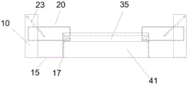
in the figure: 10 is a box cover, 11 is a first right panel, 12 is a first front panel, 13 is a first left panel, 14 is an upper panel, 15 is a first rear panel, 16 is a hinge point, 161 is a first circle, 162 is a second circle, 17 is a second fold, 20 is a display box, 21 is a second left panel, 22 is a second front panel, 23 is a connecting rod, 24 is a rotating shaft, 25 is a rotating wheel, 26 is a connecting shaft, 27 is a second rear panel, 28 is a second right panel, 30 is a bottom box, 31 is a third right panel, 32 is a third left panel, 33 is a first fold, 34 is a third front panel, 35 is a sliding groove, 36 is a third rear panel, 40 is a U-shaped box, 41 is a fourth left panel, and 42 is a fourth right panel.
Detailed Description
In order to make the aforementioned objects, features and advantages of the present application more comprehensible, the present application is described in further detail with reference to the accompanying drawings and the detailed description.
In the description of the present application, it is to be understood that the terms "intermediate," "top," "bottom," "inner," "outer," and the like are used in the orientations and positional relationships indicated in the drawings for convenience in describing the present application and simplicity in description, and do not indicate or imply that the referenced devices or elements must have a particular orientation, be constructed in a particular orientation, and be operated in a particular orientation, and thus should not be construed as limiting the present application. The terms "first", "second" and "first" are used for descriptive purposes only and are not to be construed as indicating or implying relative importance or implicitly indicating the number of technical features indicated. Thus, a feature defined as "first" or "second" may explicitly or implicitly include one or more of that feature. In the description of the present application, "a plurality" means two or more unless specifically limited otherwise.
In addition, unless expressly stated or limited otherwise, the terms "mounted," "connected," "secured," and the like are intended to be inclusive and mean, for example, that there may be a fixed connection, a removable connection, or an integral connection; can be mechanically or electrically connected; they may be connected directly or indirectly through intervening media, or they may be interconnected between two elements. The specific meaning of the above terms in the present application can be understood by those of ordinary skill in the art as appropriate.
In this application, unless expressly stated or limited otherwise, the first feature "on" or "under" the second feature may comprise direct contact of the first and second features, or may comprise contact of the first and second features not directly but through another feature in between. Also, the first feature being "on," "above" and "over" the second feature includes the first feature being directly on and obliquely above the second feature, or merely indicating that the first feature is at a higher level than the second feature. A first feature being "under," "below," and "beneath" a second feature includes the first feature being directly under and obliquely below the second feature, or simply meaning that the first feature is at a lesser elevation than the second feature.
Example 1:
referring to fig. 1-6, a display pack includes a box cover 10, a display box 20, a bottom box 30; lid 10 one end is connected with end box 30 one end, and lid 10 closes with end box 30 lid, forms between lid 10 and the end box 30 and holds the chamber, and show box 20 is located and holds the intracavity, lid 10 and show box 20 swing joint, show box 20 and end box 30 swing joint, and when lid 10 overturns to open for end box 30 relatively, lid 10 drives show box 20 and removes to expand show box 20 and end box 30 simultaneously.
Specifically, the box cover 10 includes an upper panel 14, a first left panel 13, a first right panel 11, a first front panel 12 and a first rear panel 15 are arranged around the upper panel 14, and the first left panel 13, the first right panel 11, the first front panel 12 and the first rear panel 15 form an accommodating space with one open side around the upper panel 14; the bottom box 30 comprises a bottom box bottom plate, a third left panel 32, a third right panel 31, a third front panel 34 and a third rear panel 36 are arranged on the periphery of the bottom box bottom plate, the third left panel 32, the third right panel 31, the third front panel 34 and the third rear panel 36 form an accommodating space with an opening on one side around the bottom box bottom plate, the lower end edge of the first rear panel 15 is movably connected with the lower end edge of the third rear panel 36, a second crease 17 is arranged at the joint, the first rear panel 15 and the third rear panel 36 can be turned over relatively along the second crease 17, and when the box cover 10 is turned over and covered relative to the bottom box 30, an accommodating cavity is formed; when the box cover 10 is turned over and opened relative to the bottom box 30, the box cover 10 drives the display box 20 to move horizontally or obliquely so as to unfold the display box 20 and the bottom box 30 simultaneously, and at this time, the display box 20 and the bottom box 30 are relatively step-shaped. In a specific embodiment, the display box 30 may be provided without the third back panel 36, and the first back panel 15 is movably connected to the edge of the box, in which case the width of the first back panel 15 is the height of the display package, or the width of the first back panel 15 is equal to the sum of the first left panel 13 and the third left panel 32.
Specifically, the display box 20 includes a display box bottom plate, a second left panel 21, a second right panel 28, a second front panel 22 and a second rear panel 27 are arranged on the periphery of the display box bottom plate, and the second left panel 21, the second right panel 28, the second front panel 22 and the second rear panel 27 form an accommodating space with an opening on one side around the display box bottom plate.
Specifically, the box cover 10 and the display box 20 are movably connected through a connecting rod 23, the display box 20 is step-shaped relative to the bottom box 30, and in another embodiment, the box cover 10 and the display box 20 can also be movably connected through a ribbon; the second left panel 21 and the second right panel 28 are both provided with a connecting shaft 26; one end of the connecting rod 23 is hinged on the first left panel 13 and is close to one end of the first front panel 12, the other end of the connecting rod 23 is hinged with the connecting shaft 26, specifically, one end of the connecting rod is hinged on the inner side of the first left panel 13, and the other end of the connecting rod is hinged on the outer side of the second left panel 21, preferably, the hinged position is close to one end of the upper panel 14, but not limited to, the hinged position can also be close to one end of the opening of the box cover 10. In a specific embodiment, the number of the connecting rods 23 is two, the two connecting rods are respectively hinged to the left side and the right side of the display box 20, one end of the connecting rod 23 on the left side of the display box 20 is hinged to one end of the first left panel 13 close to the first front panel 12, and the other end of the connecting rod 23 is hinged to the connecting shaft 26 on the left side of the display box 20; one end of the connecting rod 23 on the right side of the display box 20 is hinged to the end of the first right panel 11 close to the first front panel 12, and the other end of the connecting rod is hinged to the connecting shaft 26 on the right side of the display box 20.
Specifically, the second left panel 21 and the second right panel 28 are provided with a rotating shaft 24 at one end close to the second front panel 22, the second left panel 21 and the second right panel 28 are provided with shaft holes matched with the rotating shaft 24, the rotating shaft 24 is fixedly connected with the shaft holes, the third left panel 32 and the third right panel 31 are provided with a chute 35 at one side of the accommodating cavity, and the rotating shaft 24 is located in the chute 35 and can slide linearly along the chute 35; the intersection line of the bottom plate of the bottom box and the third left panel 32 is a first crease 33, and the sliding chute 35 is parallel to the first crease 33; in a specific embodiment, the rotating wheel 25 is disposed on the rotating shaft 24, the rotating wheel 25 is disposed in the sliding slot 35, the rotating wheel 25 slides along the sliding slot 35, and the width of the sliding slot 35 is slightly larger than the diameter of the rotating wheel 25, so that the rotating wheel 25 slides along the sliding slot 35, and the vertical displacement of the rotating wheel 25 is limited. In another specific embodiment, the third left panel 32 and the third right panel 31 are provided with slide rails on one side of the accommodating cavity, and the slide rails are not provided with the slide grooves 35, and the slide rails are adapted to the rotating wheel 25, and the rotating wheel 25 can slide along the slide rails.
Specifically, the top panel 14 expandes along the upset of second crease 17, it drives connecting rod 23 and drives the 14 directions in the panel of show 20 simultaneously and removes to the top panel, runner 25 is located the 14 moving direction horizontal slip of panel in the spout 35 that make progress, runner 25 can reduce the frictional force between show box 20 and the end box 30, after the panel 14 is expanded, first rear panel 15 and end box 30 bottom plate are on same horizontal plane, be convenient for support show box 20, stable in structure, it is steady to place.
Specifically, referring to fig. 6, fig. 6 is a schematic diagram of determining a position of a connecting shaft 26 of the display box 20 in this embodiment, one end of a connecting rod 23 is hinged to the first left panel 13, and is close to one end of the first front panel 12 and close to one side of the upper panel 14, and the other end is connected to the connecting shaft 26, when the box cover 10 is closed, that is, when the box cover 10 is closed with the bottom box 30, the first circle 161 is drawn by taking a hinge point 16 between the connecting rod 23 and the first left panel 13 as a center of a circle, and the length of the connecting rod 23 as a radius; opening the unfolding box cover 10, moving the display box 20 towards the box cover 10, unfolding the display box 20 and the bottom box 30, and positioning the first back panel 15 and the bottom plate of the display box 20 on the same horizontal plane, so that a second circle 162 is drawn by taking the hinge point 16 of the connecting rod 23 and the first left panel 13 as the center of a circle and the length of the connecting rod 23 as the radius; the first circle 161 and the second circle 162 are located at the intersection point of the second left panel 21, i.e. the position of the connecting axis 26.
Specifically, the display box 20 and the bottom box 30 are provided with detachable limiting frames, and the limiting frames are provided with limiting holes matched with the packaged objects. Through setting up spacing, guarantee by the distance between the packing material to and can fix by the packing material, prevent to rock the striking by the packing material.
A display packaging box comprises a box cover 10, a display box 20 and a bottom box 30; lid 10 one end is connected with end box 30 one end, and lid 10 closes with end box 30 lid, forms between lid 10 and the end box 30 and holds the chamber, and show box 20 is located and holds the intracavity, lid 10 and show box 20 swing joint, show box 20 and end box 30 swing joint, and when lid 10 overturns to open for end box 30 relatively, lid 10 drives show box 20 horizontal migration, in order to expand simultaneously show box 20 and end box 30. This show packing carton lid 10 passes through connecting rod 23 with show box 20 to be connected, upset lid 10 drives show box 20, expand show box 20 and end box 30 simultaneously, show box 20 and end box 30 are the step form relatively, all can place in show box 20 and the end box 30 by the packing material, show or storing area is big, when the box 30 upset is opened in the relative end of lid 10, lid 10 rear panel and end box 30 bottom plate are at same horizontal plane, stable in structure places steadily, non-deformable simultaneously.
Example 2:
referring to fig. 7-12, a double-open display package comprises two display packages symmetrically arranged along a first front panel 12, wherein third left panels 32 of the two display packages are connected into a whole to form a fourth left panel 41, and third right panels 31 of the two display packages are connected into a whole to form a fourth right panel 42, and meanwhile, sliding grooves 35 are also connected with each other. In this embodiment, the bottom box 30 is not provided with a third front panel and a third rear panel, the bottom boxes 3 of the two display packaging boxes are connected into a whole to form a U-shaped box 40, the two box covers are turned over along the second fold 17 to open the double-open packaging box, after the double-open packaging box is opened, the two first rear panels and the bottom surface of the U-shaped box 40 are at the same horizontal position, the two display boxes are at the horizontal position, the two display boxes are in a step shape relative to the U-shaped box 40, the structure is stable, and the display area is large.
Specifically, the box cover 10 and the display box 20 are movably connected through a connecting rod 23, the display box 20 is step-shaped relative to the bottom U-shaped box 40, and in another embodiment, the box cover 10 and the display box 20 can also be movably connected through a ribbon; the second left panel 21 and the second right panel 28 are both provided with a connecting shaft 26; one end of the connecting rod 23 is hinged on the first left panel 13 and is close to one end of the first front panel 12, and the other end of the connecting rod 23 is hinged with the connecting shaft 26, specifically, the hinged position is located at the inner side of the first left panel 13, preferably, the hinged position is close to one end of the upper panel 14, as shown in fig. 10, but not limited thereto, the hinged position can also be close to one end of the opening of the box cover 10, as shown in fig. 9. In a specific embodiment, the number of the connecting rods 23 is two, the two connecting rods are respectively hinged to the left side and the right side of the display box 20, one end of the connecting rod 23 on the left side of the display box 20 is hinged to one end of the first left panel 13 close to the first front panel 12, and the other end of the connecting rod 23 is hinged to the connecting shaft 26 on the left side of the display box 20; one end of the connecting rod 23 on the right side of the display box 20 is hinged to the end of the first right panel 11 close to the first front panel 12, and the other end of the connecting rod is hinged to the connecting shaft 26 on the right side of the display box 20.
Specifically, in this embodiment, the top panel 14 is a hollow structure, the top panel 14 is provided with a display window with a hollow hole, a decorative lamp is disposed in the display window, and a physical switch for turning on the decorative lamp is disposed on the outer surface of the top panel 14, so as to improve the aesthetic property of the packing box. The double-opening display packaging box is exquisite and stable in structure, large in display area, capable of being stored or used repeatedly and beneficial to environmental protection.
In a specific embodiment, as shown in fig. 10, the first front panel 12 is not provided in two symmetrical display packages, and the two display packages are symmetrically arranged along the plane of the first front panel, in this embodiment, the accommodating space of the U-shaped box can be enlarged to a certain extent without providing the first front panel 12.
The above description is only for the specific embodiments of the present invention, but the scope of the present invention is not limited thereto, and any person skilled in the art can easily conceive of the changes or substitutions within the technical scope of the present invention, and all the changes or substitutions should be covered within the scope of the present invention. Therefore, the protection scope of the present invention shall be subject to the protection scope of the appended claims.
Claims (10)
1. A display packaging box is characterized by comprising a box cover, a display box and a bottom box; one end of the box cover is connected with one end of the bottom box, the box cover is covered with the bottom box, an accommodating cavity is formed between the box cover and the bottom box, and the display box is positioned in the accommodating cavity; the lid with the show box passes through connecting piece swing joint, show box and end box swing joint, the lid is relative when the end box upset is opened, the lid drives the show box removes to expand simultaneously show box and end box.
2. The display pack of claim 1 wherein the lid comprises a first left panel, a first right panel; the display box comprises a second left panel and a second right panel, one end of the connecting piece is hinged to the first left panel or the first right panel, and the other end of the connecting piece is hinged to the second left panel or the second right panel.
3. The display pack of claim 2 wherein the connecting member is a connecting rod or ribbon; the display box is step-shaped relative to the bottom box when unfolded.
4. The display pack of claim 3, wherein the number of the connecting members is two, one of the connecting members is hinged at one end to the inner side of the first left panel and at the other end to the outer side of the second left panel; one end of the other connecting piece is hinged to the inner side of the first right panel, and the other end of the other connecting piece is hinged to the outer side of the second right panel.
5. The display pack of claim 4, wherein the display box further comprises a second front panel; the end box includes third left surface board, third right surface board, the one end that is close to the second front panel on second left surface board, the second right surface board all is equipped with the pivot, the one side that is located the chamber that holds on third left surface board, the third right surface board all is equipped with the spout, the pivot is located the spout and slides along the spout straight line.
6. The display package of claim 5 wherein the shaft has a roller that is positioned within the slot and rolls along the slot.
7. The display pack of claim 6 wherein the lid further comprises a first rear panel and the base box comprises a third rear panel, the first rear panel width being the sum of the first left panel width and the third left panel width, the lower end edge of the first rear panel being connected to the lower end edge of the third rear panel to form the receiving cavity.
8. A double display pack comprising two display packs according to any one of claims 1 to 7 arranged symmetrically, the third left panels of the two display packs being connected together to form a fourth left panel and the third right panels of the two display packs being connected together to form a fourth right panel.
9. A double-open display packing box according to claim 8, wherein the box cover further comprises an upper panel, the upper panel is a hollow structure, and the upper panel is provided with a display window with a hollow hole.
10. A double display package as recited in claim 9, wherein said display window is provided with a decorative light.
Priority Applications (1)
| Application Number | Priority Date | Filing Date | Title |
|---|---|---|---|
| CN202010784974.9A CN111824548A (en) | 2020-08-06 | 2020-08-06 | Display packaging box |
Applications Claiming Priority (1)
| Application Number | Priority Date | Filing Date | Title |
|---|---|---|---|
| CN202010784974.9A CN111824548A (en) | 2020-08-06 | 2020-08-06 | Display packaging box |
Publications (1)
| Publication Number | Publication Date |
|---|---|
| CN111824548A true CN111824548A (en) | 2020-10-27 |
Family
ID=72920942
Family Applications (1)
| Application Number | Title | Priority Date | Filing Date |
|---|---|---|---|
| CN202010784974.9A Pending CN111824548A (en) | 2020-08-06 | 2020-08-06 | Display packaging box |
Country Status (1)
| Country | Link |
|---|---|
| CN (1) | CN111824548A (en) |
Cited By (1)
| Publication number | Priority date | Publication date | Assignee | Title |
|---|---|---|---|---|
| CN115838027A (en) * | 2023-02-17 | 2023-03-24 | 成都世源频控技术股份有限公司 | Modular radar simulator |
-
2020
- 2020-08-06 CN CN202010784974.9A patent/CN111824548A/en active Pending
Cited By (2)
| Publication number | Priority date | Publication date | Assignee | Title |
|---|---|---|---|---|
| CN115838027A (en) * | 2023-02-17 | 2023-03-24 | 成都世源频控技术股份有限公司 | Modular radar simulator |
| CN115838027B (en) * | 2023-02-17 | 2023-05-12 | 成都世源频控技术股份有限公司 | Modularized radar simulator |
Similar Documents
| Publication | Publication Date | Title |
|---|---|---|
| CN111824548A (en) | Display packaging box | |
| US20030168378A1 (en) | Rail-track display box | |
| JP2008542884A5 (en) | ||
| CN212501484U (en) | Show packing carton and two show packing cartons that open | |
| US7001003B1 (en) | Accessory and doll holding assembly | |
| USD517318S1 (en) | Storage container for packaged collectible items | |
| KR20130027806A (en) | Packing case | |
| CN216154544U (en) | Double-door wine box | |
| CN214029611U (en) | Pull formula packing carton | |
| CN211336901U (en) | Liftable packing carton | |
| CN207902973U (en) | A kind of packing box showing product | |
| CN220181343U (en) | Swing box | |
| CN110789824A (en) | Liftable packing carton | |
| CN210592965U (en) | Supportable cosmetic bottle packaging box | |
| CN207191117U (en) | A kind of instrument trolley | |
| CN214595270U (en) | Folding portable exhibition frame | |
| CN112208902B (en) | Layered packaging carton | |
| CN215362323U (en) | Display packaging box | |
| CN2647760Y (en) | Self-lifting and lowering articles storing box | |
| CN203512245U (en) | Vertical surface display packaging box | |
| CN219353478U (en) | Be applied to portable exhibition cabinet in interim exhibition place | |
| CN206284617U (en) | A kind of Novel variable rack | |
| CN214058210U (en) | Display packaging box | |
| CN217946117U (en) | Gift box | |
| CN214268315U (en) | Packing carton with show structure |
Legal Events
| Date | Code | Title | Description |
|---|---|---|---|
| PB01 | Publication | ||
| PB01 | Publication | ||
| SE01 | Entry into force of request for substantive examination | ||
| SE01 | Entry into force of request for substantive examination |