CN111824081A - Auxiliary lifting support leg for steel pipe transport vehicle based on constructional engineering instrument - Google Patents
Auxiliary lifting support leg for steel pipe transport vehicle based on constructional engineering instrument Download PDFInfo
- Publication number
- CN111824081A CN111824081A CN202010765792.7A CN202010765792A CN111824081A CN 111824081 A CN111824081 A CN 111824081A CN 202010765792 A CN202010765792 A CN 202010765792A CN 111824081 A CN111824081 A CN 111824081A
- Authority
- CN
- China
- Prior art keywords
- steel pipe
- screw rod
- rod
- vehicle based
- sliding block
- Prior art date
- Legal status (The legal status is an assumption and is not a legal conclusion. Google has not performed a legal analysis and makes no representation as to the accuracy of the status listed.)
- Withdrawn
Links
Images

Classifications
-
- B—PERFORMING OPERATIONS; TRANSPORTING
- B60—VEHICLES IN GENERAL
- B60S—SERVICING, CLEANING, REPAIRING, SUPPORTING, LIFTING, OR MANOEUVRING OF VEHICLES, NOT OTHERWISE PROVIDED FOR
- B60S9/00—Ground-engaging vehicle fittings for supporting, lifting, or manoeuvring the vehicle, wholly or in part, e.g. built-in jacks
- B60S9/14—Ground-engaging vehicle fittings for supporting, lifting, or manoeuvring the vehicle, wholly or in part, e.g. built-in jacks for both lifting and manoeuvring
- B60S9/16—Ground-engaging vehicle fittings for supporting, lifting, or manoeuvring the vehicle, wholly or in part, e.g. built-in jacks for both lifting and manoeuvring for operating only on one end of vehicle
- B60S9/20—Ground-engaging vehicle fittings for supporting, lifting, or manoeuvring the vehicle, wholly or in part, e.g. built-in jacks for both lifting and manoeuvring for operating only on one end of vehicle with fluid-pressure lift
Abstract
The invention relates to the technical field of auxiliary equipment for steel pipe instrument transportation in constructional engineering, in particular to an auxiliary lifting support leg for a steel pipe transportation vehicle based on constructional engineering instruments. The rotating wheels are symmetrically arranged inside the two groups of lifting outer frames, and the rotating wheels are rotated and matched with elastic supports of the springs to enable the steel pipes to be stirred upwards and conveyed upwards continuously, so that the steel pipes are convenient to convey, manual carrying by workers is not needed, the labor burden of the workers is effectively reduced, and the work safety in the lifting process is convenient to guarantee.
Description
Technical Field
The invention relates to the technical field of auxiliary equipment for steel pipe instrument transportation in constructional engineering, in particular to an auxiliary lifting support leg for a steel pipe transportation vehicle based on constructional engineering instruments.
Background
Along with the development and progress of science and technology, the living standard of people is increasingly improved, along with the improvement of the economic standard of people, the construction of urban groups is also increasingly perfected, steel pipes are generally required to be used in the construction of the existing urban building engineering, the water channel circulation is realized by the connection and the laying of the steel pipes, and a large number of steel pipes are required to be used as a channel connection main body in the pipeline laying for the building engineering, so that a large number of steel pipe transportation is often required;
present steel pipe conveyer for building engineering apparatus, transport vechicle through adopting the formula of hanging, because the appearance of steel pipe is round rod shape, and its main part of steel pipe as pipe laying is longer, it is inconvenient to lead to adopting direct lifting device to lift in-process operation, therefore, the steel pipe is carrying out the loading in-process, mostly need staff's manual transport to lift, long-time transport lifts, lead to staff intensity of labour big, and if lead to the hand pine to take off owing to tired in the handling, lead to the steel pipe landing to produce dangerous accident easily, for this reason we have proposed a steel pipe transport vechicle based on building engineering apparatus and have solved above-mentioned problem with supplementary lift landing leg.
Disclosure of Invention
The invention aims to provide an auxiliary lifting support leg for a steel pipe transport vehicle based on constructional engineering equipment, and aims to solve the problems that when the existing steel pipe is loaded before being transported, the steel pipe is not convenient to directly lift due to the influence of the length and the shape of the steel pipe, manual carrying is needed in the lifting and loading process, the labor burden of workers is greatly increased, and dangerous accidents are easy to occur in the carrying and loading process.
In order to achieve the purpose, the invention provides the following technical scheme: an auxiliary lifting leg for a steel pipe transport vehicle based on constructional engineering equipment comprises a carriage main body, a first servo motor, a second servo motor, a belt pulley transmission mechanism, a hydraulic telescopic rod and a third servo motor, wherein a slide rail is fixedly installed at the bottom of the carriage main body, a first screw rod is inserted into the slide rail in a penetrating manner, one end of the first screw rod is fixedly connected with the first servo motor, a sliding block is sleeved on the outer side of the first screw rod, a connecting plate is fixedly welded at the bottom of the sliding block, a rotating shaft is rotatably connected to the left side below the connecting plate, the second servo motor is fixedly connected to one end of the rotating shaft, lifting outer frames are fixedly installed on the outer side of the rotating shaft, the lifting outer frames are provided with two groups, the two groups of lifting outer frames are arranged in a bilateral symmetry manner, and an adjusting mechanism is fixedly connected between, the adjusting mechanisms are provided with two groups, a belt pulley transmission mechanism is fixedly connected between the two groups of adjusting mechanisms, a bearing plate is slidably connected between the front surfaces of the bottoms of the two groups of lifting outer frames, a hydraulic telescopic rod is fixedly installed on the front surface of the bearing plate, a support plate is fixedly installed on a power output shaft of the hydraulic telescopic rod, the two groups of lifting outer frames are symmetrically and rotatably connected with worms in inner parts, the worms are vertically inserted in the lifting outer frames, one end of the bottom of each group of worms is fixedly connected with a third servo motor, cavities are uniformly and symmetrically formed in the two groups of lifting outer frames, clamping seats are embedded in the cavities in each group, springs are fixedly installed in the cavities in each group, one ends of the clamping seats close to the middle positions of the two groups of lifting outer frames are rotatably connected with rotating wheels, and a first bevel gear is fixedly installed on the axial positions of, and the outside meshing of first bevel gear has second bevel gear, mutually perpendicular between second bevel gear and the first bevel gear, the axle center rigidity welding of second bevel gear has the transfer line, and the other end outside cover of transfer line is equipped with the rod cover, the rod cover rotates to be connected in the inside of lifting the frame, and the outside fixed welding of rod cover has the worm wheel.
Preferably, the inside of the sliding block is provided with a threaded hole, the first screw rod is inserted into the threaded hole formed in the sliding block in a penetrating manner, the threaded hole formed in the sliding block is matched with threads assembled on the outer side of the first screw rod, and the sliding block is in threaded rotary connection with the first screw rod through threaded engagement.
Preferably, the sliding block is embedded in the sliding rail, the outer size of the sliding block is matched with the inner size of the sliding rail, and the sliding block is connected with the sliding rail in a sliding mode.
Preferably, adjustment mechanism's inner wall is including mount, thread bush and second screw rod, the mount is provided with two sets ofly altogether, and is two sets of the mount is fixed welding respectively in two sets of the front of frame lifts, every group the inside of mount is fixed to be inlayed and is had the thread bush, and two sets of it is equipped with the second screw rod to run through to insert between the thread bush, the screw thread opposite direction of assembly on the outer wall of the second screw rod left and right sides, every group the screw thread of assembly on the thread bush inner wall respectively with the screw thread looks adaptation of assembly on the second screw rod outer wall.
Preferably, a connector is fixedly mounted at one end of the outer side of the second screw rod in the adjusting mechanism in a group below, a force application rod is inserted into the connector in a penetrating mode, the force application rod is connected with the connector in a sliding mode, two ends of the belt pulley transmission mechanism are respectively fixedly connected to the upper group of second screw rods and the lower group of second screw rods in the adjusting mechanism, and the two groups of second screw rods are connected through the belt pulley transmission mechanism in a transmission mode.
Preferably, the supporting plates are arranged in two groups, and the two groups of supporting plates are in crossed rotary connection.
Preferably, the outside size of grip slipper and the inside size looks adaptation of cavity, sliding connection between grip slipper and the cavity, the one end fixed connection of spring is in the inside of cavity, the other end fixed mounting of spring is on the grip slipper, the grip slipper passes through the elastic telescopic connection between spring and the cavity.
Preferably, the outer wall of the rotating wheel is uniformly fixed with friction blocks, and the friction blocks are triangular in shape.
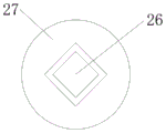
Preferably, a square groove is formed in the rod sleeve, the transmission rod is inserted into the square groove formed in the rod sleeve, the size of the outer side of one end of the transmission rod, which is inserted into the square groove formed in the rod sleeve, is matched with the size of the square groove formed in the rod sleeve, the transmission rod is connected with the rod sleeve in a sliding mode, teeth assembled on the outer side of the worm wheel are matched with teeth assembled on the outer side of the worm, and the worm wheel is in meshing transmission connection with the worm through meshing of the teeth.
Compared with the prior art, the invention has the beneficial effects that:
1. the steel pipe lifting device is characterized in that two groups of lifting outer frames are symmetrically arranged between the two groups of lifting outer frames, and the two groups of lifting outer frames are symmetrically provided with the rotating wheels inside, so that when the device works, the steel pipe entering the two groups of lifting outer frames can be stirred upwards by the rotation of the rotating wheels under the action of friction resistance through the rotation of the rotating wheels and the elastic support of the springs, and the steel pipe is continuously conveyed upwards between the two groups of lifting outer frames through reciprocating and continuous stirring, so that the steel pipe conveying is convenient and fast, the manual carrying of workers is not needed, the labor burden of the workers is effectively reduced, and the work safety in the lifting process is convenient to ensure;
2. the sliding block is in threaded rotary connection with the first screw rod, so that the position of the sliding block can be moved and adjusted by rotating the first screw rod when the device is used, and meanwhile, the lifting outer frames on the right side are matched with the connecting plate to be in rotary connection with each other, so that the lifting outer frames can be collected into the bottom of the carriage body through rotary movement when the device is used, the lifting outer frames can be collected conveniently, and the device can be collected flexibly when not used;
3. fix the front at the loading board through setting up hydraulic telescoping rod, make the device when using, through hydraulic telescoping rod's flexible, can drive the backup pad and remove, thereby make the backup pad support subaerial, be favorable to guaranteeing the support stability of the device, and simultaneously, it is the rotatory setting of cross form to set up the backup pad, make the device when using, can expand according to the demand when using, be favorable to promoting the holding surface between backup pad and the ground, make the backup pad expand or accomodate through rotating, the effectual use flexibility that ensures the device.
Description of the drawings:
in order to more clearly illustrate the embodiments of the present invention or the technical solutions in the prior art, the drawings used in the description of the embodiments or the prior art will be briefly described below, it is obvious that the drawings in the following description are only some embodiments of the present invention, and for those skilled in the art, other drawings can be obtained according to the drawings without creative efforts.
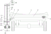
FIG. 1 is a schematic front view of the structure of the present invention;
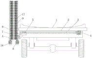
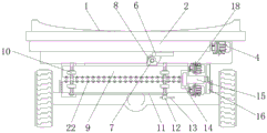
FIG. 2 is a schematic sectional elevation view of the structure of the present invention;
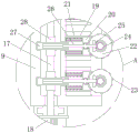
FIG. 3 is an enlarged view of the structure at A in FIG. 2 according to the present invention;
FIG. 4 is a perspective view of the support plate of the present invention;
FIG. 5 is a schematic side sectional view of the construction of the lever sleeve and the transmission lever of the present invention;
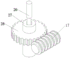
FIG. 6 is a perspective view of the worm gear and worm connection structure of the present invention;
fig. 7 is a front view schematically illustrating the structure of the present invention in the storage state.
In the figure: 1. a carriage main body; 2. a slide rail; 3. a first screw; 4. a first servo motor; 5. a slider; 6. a connecting plate; 7. a rotating shaft; 8. a second servo motor; 9. lifting the outer frame; 10. an adjustment mechanism; 101. a fixed mount; 102. a threaded sleeve; 103. a second screw; 11. a belt pulley transmission mechanism; 12. a connector; 13. a force application rod; 14. a carrier plate; 15. a hydraulic telescopic rod; 16. a support plate; 17. a worm; 18. a third servo motor; 19. a cavity; 20. a clamping seat; 21. a spring; 22. a rotating wheel; 23. a friction block; 24. a first bevel gear; 25. a second bevel gear; 26. a transmission rod; 27. a rod sleeve; 28. a worm gear.
The specific implementation mode is as follows:
the technical solutions in the embodiments of the present invention will be clearly and completely described below with reference to the drawings in the embodiments of the present invention, and it is obvious that the described embodiments are only a part of the embodiments of the present invention, and not all of the embodiments. All other embodiments, which can be derived by a person skilled in the art from the embodiments given herein without making any creative effort, shall fall within the protection scope of the present invention.
Referring to fig. 1-7, an embodiment of the present invention is shown: an auxiliary lifting support leg for a steel pipe transport vehicle based on constructional engineering equipment comprises a carriage main body 1, a first servo motor 4, a second servo motor 8, a belt pulley transmission mechanism 11, a hydraulic telescopic rod 15 and a third servo motor 18, wherein a slide rail 2 is fixedly arranged at the bottom of the carriage main body 1, a first screw rod 3 is inserted in the slide rail 2 in a penetrating manner, one end of the first screw rod 3 is fixedly connected with the first servo motor 4, a sliding block 5 is sleeved outside the first screw rod 3, a connecting plate 6 is fixedly welded at the bottom of the sliding block 5, a threaded hole is formed in the sliding block 5, the first screw rod 3 is inserted in a threaded hole formed in the sliding block 5 in a penetrating manner, a threaded hole formed in the sliding block 5 is matched with threads assembled outside the first screw rod 3, the sliding block 5 is in threaded rotation connection with the first screw rod 3 through threaded engagement, and is in threaded rotation connection with the first screw rod 3 through the arrangement of, make the device when using, through the circular telegram start of first servo motor 4, can drive and fix the first screw rod 3 rotation on its rotation output shaft, under the meshing of screw thread orders about, can make sliding block 5 remove about, remove about through sliding block 5 for the device moves into or shifts out the bottom of carriage main part 1, is convenient for accomodate when not using the device and deposits, is favorable to guaranteeing that the device carries on the car, and uses nimble convenience when expanding.
Sliding block 5 inlays in the inside of slide rail 2, and sliding block 5's outside size and slide rail 2's inside size looks adaptation, sliding connection between sliding block 5 and the slide rail 2, inlay in the inside of slide rail 2 through setting up sliding block 5, restrict with the help of the inside of slide rail 2 for the device is when using, and sliding block 5 can not the skew rotation from beginning to end, when first screw rod 3 rotates and carries out screw drive to sliding block 5, the effectual stability that ensures screw drive and remove.
A rotating shaft 7 is rotatably connected to the left side below the connecting plate 6, one end of the rotating shaft 7 is fixedly connected with a second servo motor 8, lifting outer frames 9 are fixedly installed on the outer side of the rotating shaft 7, the lifting outer frames 9 are arranged in two groups, the two groups of lifting outer frames 9 are arranged in a bilateral symmetry manner, when the device is used, the sliding block 5 moves left and right in the sliding rail 2 through the rotary connection of the screw thread, when the sliding block 5 moves to the left end position in the sliding rail 2, the second servo motor 8 is electrified and started, the rotating shaft 7 fixed on the rotating output shaft can be driven to rotate, thereby make axis of rotation 7 drive lift frame 9 rotate and put right for lift frame 9 and be vertical state and put, the circular telegram that leads to second servo motor 8 starts to drive and lifts frame 9 rotatory, is favorable to the adjustment to lift the horizontal position of frame 9, is convenient for accomodate the use.
An adjusting mechanism 10 is fixedly connected between two groups of lifting outer frames 9, the inner wall of the adjusting mechanism 10 comprises two groups of fixing frames 101, thread sleeves 102 and second screw rods 103, the two groups of fixing frames 101 are respectively fixedly welded on the front surfaces of the two groups of lifting outer frames 9, the thread sleeves 102 are fixedly embedded in the fixing frames 101, the second screw rods 103 are inserted between the two groups of thread sleeves 102 in a penetrating manner, the directions of the threads assembled on the outer walls of the left side and the right side of the second screw rods 103 are opposite, the threads assembled on the inner wall of each group of thread sleeves 102 are respectively matched with the threads assembled on the outer wall of the second screw rods 103, when the device is used, the thread sleeves 102 which are symmetrical on the left side and the right side are respectively sleeved on the left end and the right end of the second screw rods 103, the thread sleeves 102 are rotatably connected with the second screw rods 103 through threads, and the directions of the threads assembled on the, when the device is used, the second screw rod 103 is rotated, under the meshing and driving effects of the threads, the second screw rod 103 drives the thread sleeves 102 on the two sides to move in opposite directions synchronously, so that the distance between the two groups of lifting outer frames 9 can be flexibly adjusted according to requirements during use, the device is suitable for lifting of steel pipes of different specifications, and the application range of the device is effectively guaranteed.
The two groups of adjusting mechanisms 10 are arranged, the belt pulley transmission mechanisms 11 are fixedly connected between the two groups of adjusting mechanisms 10, one end of the outer side of the second screw 103 in the lower group of adjusting mechanisms 10 is fixedly provided with a connector 12, the interior of the connector 12 is inserted with a force application rod 13 in a penetrating way, the force application rod 13 is connected with the connector 12 in a sliding way, two ends of the belt pulley transmission mechanism 11 are respectively and fixedly connected with the second screw 103 in the upper and lower groups of adjusting mechanisms 10, the two groups of second screws 103 are in transmission connection through the belt pulley transmission mechanism 11, the two groups of adjusting mechanisms 10 are connected and transmitted through the belt pulley transmission mechanism 11, the upper and lower groups of second screws 103 are enabled to rotate simultaneously through the transmission of the belt pulley transmission mechanism 11, the stable consistency of the upper and lower ends when the distance between the lifting outer frames 9 on the left and right sides is adjusted is effectively ensured, and meanwhile, the connector 12 is, and set up application of force pole 13 and insert and establish inside connector 12, through the force application arm of force of connector 12 extension second screw rod 103 when rotating, be favorable to making the device more laborsaving when adjusting, simultaneously, through the position of slide adjustment application of force pole 13 in connector 12 inside for application of force pole 13 can be adjusted according to the demand when using in a flexible way, and the application of force is convenient when being favorable to the guarantee to rotate.
The bearing plate 14 is connected between the front faces of the bottoms of the two groups of lifting outer frames 9 in a sliding manner, the front faces of the bearing plate 14 are fixedly provided with the hydraulic telescopic rods 15, the power output shafts of the hydraulic telescopic rods 15 are fixedly provided with the support plates 16, the support plates 16 are arranged in two groups, and the two groups of support plates 16 are in crossed rotary connection, when the device is used, the bearing plate 14 is connected between the two groups of lifting outer frames 9 in a sliding manner, the bearing plate 14 can not limit the movement adjustment of the lifting outer frames 9 through the sliding connection, meanwhile, the hydraulic telescopic rods 15 are fixed on the outer sides of the bearing plate 14, when the device is used, the support plates 16 fixed at the bottoms of the hydraulic telescopic rods 15 are supported on the ground through the telescopic supports of the hydraulic telescopic rods 15 after being electrified, under the supporting action of the hydraulic telescopic rods 15, the lifting outer frames 9 are stable, the device's job stabilization nature has effectually been ensured, simultaneously, sets up backup pad 16 and can rotate alternately and open, is favorable to improving the backup pad 16 to the support area on ground, is convenient for ensure the device's support stability.
The two groups of lifting outer frames 9 are symmetrically and rotatably connected with worms 17, the worms 17 are vertically inserted into the lifting outer frames 9, one end of the bottom of each group of worms 17 is fixedly connected with a third servo motor 18, the two groups of lifting outer frames 9 are uniformly and symmetrically provided with cavities 19, clamping seats 20 are embedded in the cavities 19, springs 21 are fixedly arranged in the cavities 19, one ends of the clamping seats 20 close to the middle positions of the two groups of lifting outer frames 9 are rotatably connected with rotating wheels 22, the outer side sizes of the clamping seats 20 are matched with the inner sizes of the cavities 19, the clamping seats 20 are in sliding connection with the cavities 19, one ends of the springs 21 are fixedly connected inside the cavities 19, the other ends of the springs 21 are fixedly arranged on the clamping seats 20, the clamping seats 20 are elastically and telescopically connected with the cavities 19 through the springs 21, and are elastically supported between the cavities 19 and the clamping seats 20 through the springs 21, through spring 21's elastic support for spring 21 keeps the centre gripping to the steel pipe, and the effectual steel pipe that prevents drops in transportation process is convenient for ensure the device's lifting transport safety and stability.
Evenly be fixed with clutch blocks 23 on swiveling wheel 22's the outer wall, and clutch blocks 23's appearance is triangle-shaped, through setting up clutch blocks 23 fixed mounting on swiveling wheel 22's outer wall, contact friction through clutch blocks 23, effectual guarantee swiveling wheel 22 is to the extrusion conveying power of steel pipe when rotating, and simultaneously, the appearance that sets up clutch blocks 23 is triangle-shaped, under the block effect of triangle-shaped clutch blocks 23, further strengthened the lifting friction force of swiveling wheel 22 to the steel pipe, make the device carry safe and stable.
A first bevel gear 24 is fixedly installed at the axial center position of the front surface of the rotating wheel 22, a second bevel gear 25 is meshed with the outer side of the first bevel gear 24, the second bevel gear 25 and the first bevel gear 24 are perpendicular to each other, a transmission rod 26 is fixedly welded at the axial center position of the second bevel gear 25, a rod sleeve 27 is sleeved at the outer side of the other end of the transmission rod 26, the rod sleeve 27 is rotatably connected inside the lifting outer frame 9, a worm wheel 28 is fixedly welded at the outer side of the rod sleeve 27, a square groove is formed inside the rod sleeve 27, the transmission rod 26 is inserted into the square groove formed inside the rod sleeve 27, the outer side size of one end of the transmission rod 26 inserted into the square groove inside the rod sleeve 27 is matched with the size of the square groove formed inside the rod sleeve 27, the transmission rod 26 is slidably connected with the rod sleeve 27, teeth assembled at the outer side of the worm wheel 28 are matched with teeth assembled at the outer side of the, when the device is used, the third servo motor 18 is electrified to start and drive the worm 17 fixed on the rotating output shaft to rotate, the worm 17 and the worm wheel 28 are arranged to be in tooth meshing connection, so that when the device is used, the worm wheel 28 drives the rod sleeve 27 to rotate, because one end of the transmission rod 26 inserted in the rod sleeve 27 is square, the inner wall of the rod sleeve 27 is matched with the outer wall of the transmission rod 26, the transmission between the rod sleeve 27 and the transmission rod 26 is stable, the transmission rod 26 rotates synchronously along with the worm wheel 28 to drive the second bevel gear 25 fixed on one end to rotate, under the meshing transmission action between the second bevel gear 25 and the first bevel gear 24, the rotating wheel 22 rotates, the rotating directions of the two groups of third servo motors 18 are opposite, the rotating wheels 22 corresponding to the left side and the right side rotate oppositely, and are in frictional contact with the outer wall of the steel pipe when the rotating wheel, under the extrusion conveying effect for the steel pipe lifts frame 9 intermediate position along the left and right sides and upwards lifts, is favorable to stablizing the transport to the steel pipe, need not to use too much manual work to move, and the effectual steel pipe loading efficiency that has promoted, and lifts loading operation safe and reliable.
It will be evident to those skilled in the art that the invention is not limited to the details of the foregoing illustrative embodiments, and that the present invention may be embodied in other specific forms without departing from the spirit or essential attributes thereof. The present embodiments are therefore to be considered in all respects as illustrative and not restrictive, the scope of the invention being indicated by the appended claims rather than by the foregoing description, and all changes which come within the meaning and range of equivalency of the claims are therefore intended to be embraced therein. Any reference sign in a claim should not be construed as limiting the claim concerned.
Claims (9)
1. The utility model provides a steel pipe is supplementary lift landing leg for haulage vehicle based on building engineering apparatus, includes carriage main part (1), first servo motor (4), second servo motor (8), belt pulley drive mechanism (11), hydraulic telescoping rod (15) and third servo motor (18), its characterized in that: the carriage is characterized in that a sliding rail (2) is fixedly mounted at the bottom of the carriage body (1), a first screw rod (3) is inserted into the sliding rail (2) in a penetrating manner, a first servo motor (4) is fixedly connected to one end of the first screw rod (3), a sliding block (5) is sleeved on the outer side of the first screw rod (3), a connecting plate (6) is fixedly welded to the bottom of the sliding block (5), a rotating shaft (7) is rotatably connected to the left side of the lower portion of the connecting plate (6), a second servo motor (8) is fixedly connected to one end of the rotating shaft (7), lifting outer frames (9) are fixedly mounted on the outer side of the rotating shaft (7), two groups of the lifting outer frames (9) are arranged, the two groups of the lifting outer frames (9) are arranged in a bilateral symmetry manner, two groups of adjusting mechanisms (10) are fixedly connected between the lifting outer frames (9), and, and two sets of be fixedly connected with belt pulley drive mechanism (11) between adjustment mechanism (10), two sets of sliding connection has loading board (14) between the bottom of frame (9) lifts openly, and the front fixed mounting of loading board (14) has hydraulic telescoping rod (15), fixed mounting has backup pad (16) on the power output shaft of hydraulic telescoping rod (15), two sets of the inside symmetry of frame (9) lifts rotates and is connected with worm (17), and worm (17) vertical the inserting is established in the inside of frame (9) lifts, every group the bottom one end of worm (17) all fixedly connected with third servo motor (18), two sets of the inside of frame (9) lifts evenly to have seted up cavity (19) symmetrically, and every group the inside of cavity (19) all inlays and has holder (20), every group the inside fixed mounting of cavity (19) has spring (21), grip slipper (20) are close to two sets ofly lift the one end rotation of frame (9) intermediate position and be connected with swiveling wheel (22), the positive axle center fixed mounting of swiveling wheel (22) has first bevel gear (24), and the outside meshing of first bevel gear (24) has second bevel gear (25), mutually perpendicular between second bevel gear (25) and first bevel gear (24), the axle center fixed welding of second bevel gear (25) has transfer line (26), and the other end outside cover of transfer line (26) is equipped with pole cover (27), pole cover (27) rotate to be connected in the inside of lifting frame (9), and the outside fixed welding of pole cover (27) has worm wheel (28).
2. The auxiliary lifting leg for the steel pipe transportation vehicle based on the constructional engineering instrument as claimed in claim 1, wherein: the novel screw rod structure is characterized in that a threaded hole is formed in the sliding block (5), the first screw rod (3) penetrates through the threaded hole formed in the sliding block (5), the threaded hole formed in the sliding block (5) is matched with threads assembled on the outer side of the first screw rod (3), and the sliding block (5) is in threaded rotary connection with the first screw rod (3) through threaded engagement.
3. The auxiliary lifting leg for the steel pipe transportation vehicle based on the constructional engineering instrument as claimed in claim 1, wherein: sliding block (5) are inlayed in the inside of slide rail (2), and the outside size of sliding block (5) and the inside size looks adaptation of slide rail (2), sliding connection between sliding block (5) and slide rail (2).
4. The auxiliary lifting leg for the steel pipe transportation vehicle based on the constructional engineering instrument as claimed in claim 1, wherein: the inner wall of adjustment mechanism (10) is including mount (101), thread bush (102) and second screw rod (103), mount (101) are provided with two sets ofly altogether, and are two sets of mount (101) fixed weld is two sets of respectively the front of frame (9) lifts, every group the inside fixed of mount (101) is inlayed and is had thread bush (102), and is two sets of run through between thread bush (102) and insert and be equipped with second screw rod (103), the screw thread opposite direction of assembly on the outer wall of second screw rod (103) left and right sides, every group the screw thread of assembly on thread bush (102) inner wall respectively with the screw thread looks adaptation of assembly on second screw rod (103) outer wall.
5. The auxiliary lifting leg for the steel pipe transportation vehicle based on the constructional engineering instrument as claimed in claim 4, wherein: the outside one end fixed mounting of inside second screw rod (103) of adjustment mechanism (10) in the below is a set of connector (12), and the inside of connector (12) is run through and is inserted and be equipped with application of force pole (13), sliding connection between application of force pole (13) and connector (12), the both ends of belt pulley drive mechanism (11) are fixed connection respectively about two sets of on second screw rod (103) of adjustment mechanism (10) inside, two sets of connect through belt pulley drive mechanism (11) transmission between second screw rod (103).
6. The auxiliary lifting leg for the steel pipe transportation vehicle based on the constructional engineering instrument as claimed in claim 1, wherein: the supporting plates (16) are provided with two groups, and the two groups of supporting plates (16) are in crossed rotary connection.
7. The auxiliary lifting leg for the steel pipe transportation vehicle based on the constructional engineering instrument as claimed in claim 1, wherein: the utility model discloses a clamping device, including base (20), clamping holder (20), one end fixed connection in the inside of cavity (19), the outside size of clamping holder (20) and the inside size looks adaptation of cavity (19), sliding connection between clamping holder (20) and cavity (19), the one end fixed connection of spring (21) is in the inside of cavity (19), the other end fixed mounting of spring (21) is on clamping holder (20), elastic telescopic connection between clamping holder (20) through spring (21) and cavity (19).
8. The auxiliary lifting leg for the steel pipe transportation vehicle based on the constructional engineering instrument as claimed in claim 1, wherein: the outer wall of the rotating wheel (22) is uniformly fixed with friction blocks (23), and the shape of each friction block (23) is triangular.
9. The auxiliary lifting leg for the steel pipe transportation vehicle based on the constructional engineering instrument as claimed in claim 1, wherein: the worm gear is characterized in that a square groove is formed in the rod sleeve (27), the transmission rod (26) is inserted into the square groove formed in the rod sleeve (27), the size of the outer side of one end of the transmission rod (26) inserted into the square groove in the rod sleeve (27) is matched with the size of the square groove formed in the rod sleeve (27), the transmission rod (26) is connected with the rod sleeve (27) in a sliding mode, teeth assembled on the outer side of the worm gear (28) are matched with teeth assembled on the outer side of the worm (17), and the worm gear (28) is in meshing transmission connection with the worm (17) through meshing of the teeth.
Priority Applications (1)
| Application Number | Priority Date | Filing Date | Title |
|---|---|---|---|
| CN202010765792.7A CN111824081A (en) | 2020-08-03 | 2020-08-03 | Auxiliary lifting support leg for steel pipe transport vehicle based on constructional engineering instrument |
Applications Claiming Priority (1)
| Application Number | Priority Date | Filing Date | Title |
|---|---|---|---|
| CN202010765792.7A CN111824081A (en) | 2020-08-03 | 2020-08-03 | Auxiliary lifting support leg for steel pipe transport vehicle based on constructional engineering instrument |
Publications (1)
| Publication Number | Publication Date |
|---|---|
| CN111824081A true CN111824081A (en) | 2020-10-27 |
Family
ID=72919320
Family Applications (1)
| Application Number | Title | Priority Date | Filing Date |
|---|---|---|---|
| CN202010765792.7A Withdrawn CN111824081A (en) | 2020-08-03 | 2020-08-03 | Auxiliary lifting support leg for steel pipe transport vehicle based on constructional engineering instrument |
Country Status (1)
| Country | Link |
|---|---|
| CN (1) | CN111824081A (en) |
Cited By (1)
| Publication number | Priority date | Publication date | Assignee | Title |
|---|---|---|---|---|
| CN112403850A (en) * | 2020-11-26 | 2021-02-26 | 陈定桥 | A portable baking finish device for car touch-up paint |
-
2020
- 2020-08-03 CN CN202010765792.7A patent/CN111824081A/en not_active Withdrawn
Cited By (1)
| Publication number | Priority date | Publication date | Assignee | Title |
|---|---|---|---|---|
| CN112403850A (en) * | 2020-11-26 | 2021-02-26 | 陈定桥 | A portable baking finish device for car touch-up paint |
Similar Documents
| Publication | Publication Date | Title |
|---|---|---|
| CN113560759B (en) | Anticorrosive natural gas line lays welding auxiliary device | |
| CN107023440B (en) | Special clamp for wind power blade hoisting rotation | |
| CN210854928U (en) | Crane lifting lug | |
| CN213569280U (en) | Hoisting accessory is used in thermal power plant's maintenance | |
| CN111824081A (en) | Auxiliary lifting support leg for steel pipe transport vehicle based on constructional engineering instrument | |
| CN202296985U (en) | Manual double-screw rod lifting trolley | |
| CN212825248U (en) | Make things convenient for height-adjusting's support for steel construction processing | |
| CN219078922U (en) | Chain traction type angular lifting trolley | |
| CN205933082U (en) | Auto repair tilting gearing for auto repair | |
| CN104594140A (en) | Rail-spanning stepping type ballast excavating machine | |
| CN204475073U (en) | One digs tiny fragments of stone, coal, etc. machine across rail step-by-step movement | |
| CN216973112U (en) | Running gear of main push-towing rope inspection device | |
| CN212832440U (en) | Driving with fixture | |
| CN213497420U (en) | Trailer bottom plate welding position device | |
| CN211664593U (en) | Soft soil foundation pit construction equipment | |
| CN209193389U (en) | A kind of loop wheel machine structure of shield machine segment | |
| CN201064905Y (en) | Hanging bogie examining and repairing manipulator | |
| CN219912551U (en) | Track inspection robot with lifting mechanism | |
| CN213059936U (en) | Hanging bracket for treating domestic sewage | |
| CN204954187U (en) | Longmen welding set | |
| CN211257127U (en) | Movable hydraulic grab bucket trash remover | |
| CN211168744U (en) | High finish trusteeship equipment | |
| CN219217344U (en) | Welding fixture for modularized house steel structure | |
| CN215797985U (en) | Axle through shaft hanger convenient to adjust | |
| CN214243543U (en) | Supporting mechanism of tower crane for building construction |
Legal Events
| Date | Code | Title | Description |
|---|---|---|---|
| PB01 | Publication | ||
| PB01 | Publication | ||
| SE01 | Entry into force of request for substantive examination | ||
| SE01 | Entry into force of request for substantive examination | ||
| WW01 | Invention patent application withdrawn after publication | ||
| WW01 | Invention patent application withdrawn after publication |
Application publication date: 20201027 |