CN111782014A - Big data computer network safety device - Google Patents
Big data computer network safety device Download PDFInfo
- Publication number
- CN111782014A CN111782014A CN202010678503.XA CN202010678503A CN111782014A CN 111782014 A CN111782014 A CN 111782014A CN 202010678503 A CN202010678503 A CN 202010678503A CN 111782014 A CN111782014 A CN 111782014A
- Authority
- CN
- China
- Prior art keywords
- plate
- shell
- mounting frame
- computer network
- rear end
- Prior art date
- Legal status (The legal status is an assumption and is not a legal conclusion. Google has not performed a legal analysis and makes no representation as to the accuracy of the status listed.)
- Granted
Links
Images


Classifications
-
- G—PHYSICS
- G06—COMPUTING; CALCULATING OR COUNTING
- G06F—ELECTRIC DIGITAL DATA PROCESSING
- G06F1/00—Details not covered by groups G06F3/00 - G06F13/00 and G06F21/00
- G06F1/16—Constructional details or arrangements
- G06F1/18—Packaging or power distribution
- G06F1/181—Enclosures
- G06F1/182—Enclosures with special features, e.g. for use in industrial environments; grounding or shielding against radio frequency interference [RFI] or electromagnetical interference [EMI]
-
- G—PHYSICS
- G06—COMPUTING; CALCULATING OR COUNTING
- G06F—ELECTRIC DIGITAL DATA PROCESSING
- G06F1/00—Details not covered by groups G06F3/00 - G06F13/00 and G06F21/00
- G06F1/16—Constructional details or arrangements
- G06F1/20—Cooling means
Abstract
The invention discloses a big data computer network safety protection device, which belongs to the technical field of computer network equipment and comprises a protection shell and a computer shell, wherein the protection shell which is used for protecting the computer shell and is in a rectangular frame structure is arranged on the outer side of the computer shell, one side of the protection shell is arranged in an open manner, a supporting plate is arranged in the protection shell, a mounting frame which is in a rectangular structure is arranged in the middle of the top end of the supporting plate, and the open end of the mounting frame faces towards the supporting plate. The invention synchronously fixes the left side wall and the right side wall of the computer network equipment, facilitates the installation of the computer network equipment by people, and also can center the computer network equipment during installation, so that the computer network equipment can be stably positioned in the middle side in the protective shell, the alignment of a display screen on the computer network equipment and a glass window on a cover plate is ensured, and the observation of the computer network equipment by people is facilitated.
Description
Technical Field
The invention relates to the technical field of computer network equipment, in particular to a big data computer network safety protection device.
Background
The combination of computer and communications has profound effects on the way computer systems are organized; the concept of "computer centric" is now completely obsolete by placing a large computer in a single room and then having the user work with their processing tasks in the room; all the computing requirements in the whole organization are processed by one computer, the old model is replaced by a new model, and a large number of independent computers which are connected with each other are used for jointly completing computing tasks under the new model; the systems are called computer networks, and with the rapid development of network technology, the application field of computer network equipment is continuously expanded, so that innovations and designs are carried out on protective devices for the computer network equipment, and the development of the network technology is promoted.
The protection device for most of existing computer network equipment can not clamp the computer network equipment and can also carry out position centering on the computer network equipment, so that the computer network equipment needs to be manually centered and clamped by a manual driving fixing structure when being fixed.
Disclosure of Invention
1. Technical problem to be solved
The present invention is directed to a big data computer network security device, so as to solve the problems mentioned in the background art.
2. Technical scheme
In order to solve the problems, the invention adopts the following technical scheme:
a big data computer network safety protection device comprises a protection shell and a computer shell, wherein the outer side of the computer shell is provided with a protection shell which protects the computer shell and is of a rectangular frame structure, one side of the protection shell is arranged in an open manner, a supporting plate is arranged in the protection shell, an installation frame which is of a rectangular structure is arranged in the middle of the top end of the supporting plate, the open end of the installation frame is arranged towards the supporting plate, two vertically arranged baffles are arranged on the inner side of the installation frame and are respectively positioned at the front end and the rear end of the installation frame, the two baffles are symmetrical about the horizontal center line of the installation frame, the installation frame is used for supporting the computer shell, a fixing mechanism for fixing the computer shell is arranged on the installation frame and comprises a first extrusion plate and a second extrusion plate which are symmetrically arranged at the top of the installation frame, and the two extrusion plates are respectively arranged at the left side and the right side of the, each extrusion plate is vertically arranged, the bottom end of each extrusion plate is provided with a sliding block, the left side and the right side of the top of the mounting frame are respectively provided with a sliding groove for the sliding block on the corresponding side to slide left and right, the bottom end of each sliding block is respectively provided with a horizontally arranged rack plate which is respectively a first rack plate and a second rack plate, teeth on the two rack plates are oppositely arranged, a transmission gear is arranged between the two rack plates and is meshed with the two rack plates, the middle part of the transmission gear is penetrated with a rotating shaft which is fixedly connected with the transmission gear, two ends of the rotating shaft are penetrated through the corresponding side baffle, the baffle is rotatably connected with the rotating shaft, one end of the rotating shaft penetrating through the rear end baffle continuously extends backwards and penetrates through the rear end side wall of the mounting frame, one end of the rotating shaft penetrating through the rear end baffle is provided with a thread ring, and the thread ring of the rotating shaft is connected with a, the locking nut is positioned at the rear side of the rear end baffle, each rack plate is horizontally provided with a limiting slide way, the inside of each limiting slide way is connected with a limiting rod in a sliding way, the two ends of each limiting rod are fixedly connected with the baffle on the corresponding side, the rear end of the protective shell extends horizontally forwards, the middle part of the supporting plate is provided with a threaded hole for the threaded rod to pass through, the threaded rod is rotatably connected with the rear end of the protective shell, the end part of the threaded rod positioned at the outer side of the rear end of the protective shell is provided with a rotating torsion block, the left side and the right side of the front surface of the supporting plate are respectively provided with limiting slide rods which are symmetrical relative to the threaded rod, the supporting plate is provided with limiting holes for the corresponding limiting slide rods to slide horizontally, one end of each limiting slide rod, which faces the rear end side wall of the protective shell, is fixedly connected with the protective shell, and the, one side of the supporting plate close to the open end of the protective shell is fixedly provided with a cover plate for covering the open end of the protective shell, and the cover plate is provided with a glass window for observing the computer shell.
Preferably, the installing frame fretwork sets up, both ends are equipped with the vertical extension board that upwards sets up respectively around the installing frame top, and extend the top middle part that the board is located the installing frame to the extension board that is located the rear end is improved level and is equipped with the screw rod, the middle part that extends the board is equipped with the through-hole that supplies the screw rod level to pass, and the helicitic texture on the through-hole is identical with the helicitic texture on the screw rod, the one end that the screw rod passed the rear end extension board is equipped with rubber extrusion piece.
Preferably, the bottom of backup pad is equipped with the first gyro wheel with the contact of the internal bottom of protecting shell, and the equidistant bottom of locating the backup pad of first gyro wheel.
Preferably, be equipped with the grafting piece that is the rectangle column structure on the apron, the inserting groove of being connected with grafting piece joint is seted up on the protective housing, the tip of grafting piece is equipped with sealed the pad, and sealed pad and the inseparable laminating of the inner wall of inserting groove, the bottom of apron is equipped with the second gyro wheel, and the second gyro wheel low side flushes the setting with protective housing's bottom.
Preferably, the equal interval is equipped with the extrusion piece on two the terminal surface that the stripper plate is in the opposite direction, and every extrusion piece all glues the rubber piece of having stuck to the one end that corresponds the side stripper plate dorsad.
3. Advantageous effects
1. The invention can drive the supporting plate in threaded connection with the threaded rod to slide on the limiting slide rod through the rotation of the threaded rod so as to facilitate the position adjustment of the supporting plate and the protective shell by people, thereby facilitating the installation and the maintenance of computer network equipment above the supporting plate when the supporting plate extends out of the protective shell, protecting the installed and maintained computer network equipment through the protective shell when the supporting plate extends into the protective shell so as to reduce the damage of external force on the computer network equipment, in addition, the cover plate is fixedly connected with the supporting plate so that the cover plate can be opened and closed with the protective shell under the driving of the supporting plate when the cover plate moves, the flexible performance of the connection between the cover plate and the protective shell is improved, and the installation and the later maintenance work of the computer network equipment in the protective shell by people are facilitated, and the protective shell is connected with the cover plate in a clamping manner, so that the computer network equipment can be protected in a cladding manner between the protective shell and the cover plate, and the use safety of the computer network equipment is ensured.
2. The invention enables the second extrusion plate to be close to or far away from the first extrusion plate under the meshing transmission of the first rack plate and the transmission gear below the first extrusion plate and the meshing transmission of the transmission gear and the second rack plate under the meshing transmission of the transmission gear and the second extrusion plate under the condition that the locking nut is screwed off the rotating shaft, so as to clamp and release the left and right side walls of the computer network equipment.
3. The free end of the screw is used for extruding the rear end face of the computer shell placed on the mounting frame through the threaded rotation of the screw on the rear end extension plate, so that the front end of the computer shell is tightly attached to the side wall of the front end extension plate, the front end and the rear end of the computer shell are fixed, the stability of the computer shell is improved, and when the screw extrudes the computer shell, the computer shell can be buffered and protected through the deformation of the rubber extrusion block on the screw.
4. According to the invention, the cover plate is connected to the open end of the protective shell in a clamping manner through the connection of the insertion block and the insertion groove, in addition, the cover plate is fixedly connected with the support plate, so that the cover plate can be driven by the support plate when the cover plate moves to open and close with the protective shell, the flexibility of the connection of the cover plate and the protective shell is improved, the installation and later maintenance work of computer network equipment in the protective shell are facilitated for people, and the cover plate can be supported by the rolling of the second roller when the cover plate is opened and closed through the arrangement that the lowest end of the second roller is flush with the surface of the bottom end of the protective shell, so that the stability of the cover plate is improved.
5. The extrusion surface of the extrusion plate forms a rugged structure through the arrangement of the extrusion blocks on the extrusion plate, the side wall of the computer shell is communicated with the outside atmosphere through the contact of the extrusion blocks and the side wall of the computer shell, so that the heat dissipation speed of the side wall of the computer shell is improved, and in addition, the extrusion force of the extrusion blocks on the side wall of the computer shell can be reduced through the deformation of the rubber blocks on the extrusion blocks, so that the protection of the computer shell is realized.
Drawings
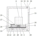
FIG. 1 is a schematic front view of the internal structure of the present invention;
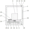
FIG. 2 is a side view of the internal structure of the present invention;
FIG. 3 is a partial side view of the internal structure of the present invention;
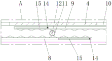
FIG. 4 is an enlarged view of the structure at A in FIG. 1;
fig. 5 is an enlarged schematic view of B in fig. 2.
Reference numerals: 1-protective housing, 2-cover plate, 3-support plate, 4-mounting frame, 5-computer housing, 6-first extrusion plate, 7-second extrusion plate, 8-first rack plate, 9-second rack plate, 10-sliding groove, 11-transmission gear, 12-rotating shaft, 13-baffle, 14-limiting rod, 15-limiting slideway, 16-sliding block, 17-extrusion block, 18-rubber block, 19-threaded rod, 20-threaded hole, 21-limiting sliding rod, 22-limiting through hole, 23-first roller, 24-rotating button block, 25-locking nut, 26-extension plate, 27-threaded rod, 28-rubber extrusion block, 29-second roller, 30-splicing block, 31-splicing groove, 32-gasket, 33-glazing.
Detailed Description
The present invention will be described in further detail with reference to the accompanying drawings and examples.
Examples
1-5, the big data computer network safety protection device comprises a protection housing 1 and a computer housing 5, the protection housing 1 is arranged on the outer side of the computer housing 5 and has a rectangular frame structure, one side of the protection housing 1 is open, a support plate 3 is arranged inside the protection housing 1, a mounting frame 4 having a rectangular structure is arranged in the middle of the top end of the support plate 3, the open end of the mounting frame 4 faces the support plate 3, two vertically arranged baffles 13 are arranged on the inner side of the mounting frame 4, the two baffles 13 are respectively arranged at the front end and the rear end of the mounting frame 4, the two baffles 13 are symmetrical about the horizontal center line of the mounting frame 4, the mounting frame 4 is used for supporting the computer housing 5, a fixing mechanism for fixing the computer housing 5 is arranged on the mounting frame 4, and the fixing mechanism comprises a first extruding plate 6, a second extruding plate, and a second extruding plate symmetrically arranged at the top of the, A second extrusion plate 7, two extrusion plates are respectively arranged at the left and right sides of the front of the mounting frame 4, each extrusion plate is vertically arranged, the bottom end of each extrusion plate is provided with a slide block 16, the opposite end surfaces of the two extrusion plates are provided with extrusion blocks 17 at equal intervals, one end of each extrusion block 17 back to the extrusion plate at the corresponding side is adhered with a rubber block 18, the extrusion surfaces of the extrusion plates form a rugged structure through the arrangement of the extrusion blocks 17 on the extrusion plates, the side wall of the computer shell 5 is communicated with the outside atmosphere through the contact of the extrusion blocks 17 and the side wall of the computer shell 5, so as to improve the heat dissipation speed of the side wall of the computer shell 5, in addition, the deformation generated by the rubber blocks 18 on the extrusion blocks 17 can reduce the extrusion pressure degree of the extrusion blocks 17 on the side wall of the computer shell 5, so as to realize the protection of the computer shell 5, the left and right sides of the top of the mounting frame 4 are respectively provided with slide grooves 10 for the slide, the bottom end of each sliding block 16 is respectively provided with a horizontally arranged rack plate, and respectively comprises a first rack plate 8 and a second rack plate 9, teeth on the two rack plates are oppositely arranged, a transmission gear 11 is arranged between the two rack plates, the transmission gear 11 is meshed with the two rack plates, a rotating shaft 12 penetrates through the middle part of the transmission gear 11, the rotating shaft 12 is fixedly connected with the transmission gear 11, two ends of the rotating shaft 12 penetrate through corresponding side baffles 13, the baffles 13 are rotatably connected with the rotating shaft 12, one end of the rotating shaft 12 penetrating through the rear end baffle 13 continues to extend backwards and penetrates through the side wall of the rear end of the mounting frame 4, one end of the rotating shaft 12 penetrating through the rear end baffle 13 is provided with a threaded ring, the threaded ring of the rotating shaft 12 is in threaded connection with a locking nut 25, the locking nut 25 is positioned at the rear side of the rear end baffle 13, each rack plate is horizontally provided with a limiting slideway 15, and the inside of each limiting slideway 15 is slidably connected, two ends of each limiting rod 14 are fixedly connected with the baffle 13 on the corresponding side;
the mounting frame 4 is arranged in a hollow way, the front end and the rear end of the top of the mounting frame 4 are respectively provided with an extending plate 26 which is vertically and upwards arranged, the extending plate 26 is positioned in the middle of the top end of the mounting frame 4, the extending plate 26 positioned at the rear end is horizontally provided with a screw 27, the middle part of the extending plate 26 is provided with a through hole for the screw 27 to horizontally pass through, the thread structure on the through hole is matched with the thread structure on the screw 27, one end of the screw 27 which passes through the rear end extending plate 26 is provided with a rubber extrusion block 28, the free end of the screw 27 is enabled to extrude the rear end face of the computer shell 5 which is positioned on the mounting frame 4 through the thread rotation of the screw 27 on the rear end extending plate 26, so that the front end of the computer shell 5 is tightly attached to the side wall of the front end extending plate 26, the fixing of the front end and the rear end of the computer shell 5, the computer shell 5 can be buffered and protected through the deformation of the rubber extrusion blocks 28 on the screw rods 27, and the heat dissipation speed of the heat at the bottom of the computer shell 5 on the mounting frame 4 can be increased through the arrangement of the hollow structure of the mounting frame 4;
the rear end of the protective shell 1 extends horizontally and forwards, the middle part of the support plate 3 is provided with a threaded through hole 20 for the threaded rod 19 to pass through, the threaded rod 19 is rotatably connected with the rear end of the protective shell 1, the end part of the threaded rod 19, which is positioned at the outer side of the rear end of the protective shell 1, is provided with a rotating block 24, the left side and the right side of the front surface of the support plate 3 are respectively provided with a limiting slide rod 21 which is symmetrical about the threaded rod 19, the support plate 3 is provided with a limiting through hole 22 for the corresponding limiting slide rod 21 to slide horizontally, one end of the limiting slide rod 21, which faces the side wall of the rear end of the protective shell 1, is fixedly connected with the protective shell 1, the support plate 3 forms a sliding structure with the protective shell 1 through the matching of the threaded rod 19 and the limiting slide rod 21, the bottom end of the support plate 3 is provided, the bottom end of the support plate 3 can be supported through the first roller 23 to improve the stability of the support plate 3, and the support plate 3 can be matched during moving through the rolling of the first roller 23 to promote the movement of the support plate 3;
a cover plate 2 for covering the open end of the protective shell 1 is fixedly arranged on one side of the support plate 3 close to the open end of the protective shell 1, a glass window 33 for observing the computer shell 5 is arranged on the cover plate 2, an insertion block 30 in a rectangular structure is arranged on the cover plate 2, an insertion groove 31 connected with the insertion block 30 in a clamping manner is arranged on the protective shell 1, a sealing gasket 32 is arranged at the end part of the insertion block 30, the sealing gasket 32 is tightly attached to the inner wall of the insertion groove 31, a second roller 29 is arranged at the bottom end of the cover plate 2, the lower end of the second roller 29 is flush with the bottom end of the protective shell 1, the cover plate 2 is connected with the insertion groove 31 in a clamping manner, the cover plate 2 is connected to the open end of the protective shell 1, and the cover plate 2 is fixedly connected with the support plate 3 when moving, so that the cover plate 2 can be driven by the support plate 3 to open, improve the flexibility ability that apron 2 and protective housing 1 are connected, make things convenient for people to the installation of the inside computer network equipment of protective housing 1 and the maintenance work in later stage, through the setting that the 29 least significant ends of second gyro wheel flush with the 1 bottom surface of protective housing, make apron 2 when being opened, when closing accessible second gyro wheel 29 roll and support apron 2 when removing to improve apron 2's stability ability.
The specific application process of the big data computer network safety protection device is as follows: when computer network equipment is installed, firstly, the rotating button block 24 is rotated to drive the threaded rod 19 to rotate, so that the supporting plate 3 in threaded connection with the threaded rod 19 can be driven to slide on the limiting slide rod 21, one end of the supporting plate 3 extends to the outer side of the protective shell 1, meanwhile, the cover plate 2 is fixedly connected with the supporting plate 3 through the cover plate 2, the cover plate 2 is driven by the supporting plate 3 to move towards one end far away from the protective shell 1 when moving, secondly, under the condition that the locking nut 25 is screwed off the rotating shaft 12, the second extrusion plate 7 is driven to move away from the first extrusion plate 6 through manually pulling the movement of the first extrusion plate 6 under the meshing of the first rack plate 8 and the transmission gear 11 and the meshing transmission of the transmission gear 11 and the second rack plate 9, so as to increase the installation area of the top end of the installation frame 4 on the computer network equipment, secondly, placing the computer network equipment on the top end of the installation frame 4, enabling the front end face of the computer network equipment to be attached to the extension plate 26 on the front end of the installation frame 4, and then manually pushing the first extrusion plate 6 to move to enable the second extrusion plate 7 to be far away from the first extrusion plate 6 under the meshing transmission of the gear and the rack so as to clamp the left side wall and the right side wall of the computer network equipment;
secondly, the free end of the screw 27 is pressed against the rear end face of the computer shell 5 placed on the mounting frame 4 by the screw rotation of the rear end extension plate 26 through the screw 27, so that the front end of the computer shell 5 is tightly attached to the side wall of the front end extension plate 26, the front end and the rear end of the computer shell 5 are fixed, the stability of the computer shell 5 is improved, when the screw 27 presses the computer shell 5, the computer shell 5 can be buffered and protected through the deformation generated by the rubber extrusion block 28 on the screw 27, secondly, the screw rod 19 is driven to rotate through the reverse rotation torsion block 24, the support plate 3 in threaded connection with the screw rod 19 slides on the limiting slide rod 21, so that the extending end of the support plate 3 is contracted to the inner side of the protective shell 1, at the moment, the cover plate 2 is in fixed connection with the support plate 3 through the fixed connection of the cover plate 2 and the protective shell 1 when moving, the protective shell 1 and the cover plate 2 are connected in a clamping manner, so that the computer network equipment is protected in a cladding manner between the protective shell 1 and the cover plate 2, and the use safety of the computer network equipment is ensured;
when the computer network equipment is used, the heat dissipation speed of the side wall of the computer shell 5 can be improved by arranging the hollow-out mounting frame 4 and the extrusion block 17 on the extrusion plate, so that the use process of the large-data computer network safety protection device is completed.
It should be understood by those skilled in the art that the above embodiments are only for illustrating the present invention and are not to be used as a limitation of the present invention, and that changes and modifications to the above embodiments are within the scope of the claims of the present invention as long as they are within the spirit and scope of the present invention.
Claims (5)
1. The big data computer network safety protection device comprises a protection shell (1) and a computer shell (5), wherein the protection shell (1) which protects the computer shell and is of a rectangular frame structure is arranged on the outer side of the computer shell (5), one side of the protection shell (1) is arranged in an open mode, the big data computer network safety protection device is characterized in that a supporting plate (3) is arranged inside the protection shell (1), a mounting frame (4) which is of a rectangular structure is arranged in the middle of the top end of the supporting plate (3), the open end of the mounting frame (4) faces the supporting plate (3), two vertically arranged baffles (13) are arranged on the inner side of the mounting frame (4), the two baffles (13) are respectively located at the front end and the rear end of the mounting frame (4), the two baffles (13) are symmetrical about the horizontal center line of the mounting frame (4), and the mounting frame (4) is used for supporting the computer shell (5), and the mounting frame (4) is provided with a fixing mechanism for fixing the computer shell (5), the fixing mechanism comprises a first extrusion plate (6) and a second extrusion plate (7) which are symmetrically arranged at the top of the mounting frame (4), the two extrusion plates are respectively arranged at the left side and the right side of the front of the mounting frame (4), and each extrusion plate is vertically arranged, the bottom end of each extrusion plate is provided with a sliding block (16), the left side and the right side of the top of the mounting frame (4) are respectively provided with a sliding chute (10) for the corresponding side sliding block (16) to slide left and right, each bottom end of the sliding block (16) is respectively provided with a rack plate which is horizontally arranged, and is respectively a first rack plate (8) and a second rack plate (9), the two teeth on the rack plates are oppositely arranged, a transmission gear (11) is arranged between the two rack plates, and the transmission gear (11) is meshed with the two rack plates, the middle part of the transmission gear (11) penetrates through a rotating shaft (12), the rotating shaft (12) is fixedly connected with the transmission gear (11), two ends of the rotating shaft (12) penetrate through corresponding side baffles (13), the baffles (13) are rotatably connected with the rotating shaft (12), one end of the rotating shaft (12) penetrating through the rear end baffle (13) continues to extend backwards and penetrates through the rear end side wall of the mounting frame (4), one end of the rotating shaft (12) penetrating through the rear end baffle (13) is provided with a threaded ring, the threaded ring of the rotating shaft (12) is in threaded connection with a locking nut (25), the locking nut (25) is positioned at the rear side of the rear end baffle (13), each rack plate is horizontally provided with a limiting slide way (15), the inside of each limiting slide way (15) is in sliding connection with a limiting rod (14), two ends of each limiting rod (14) are fixedly connected with the baffles (13) on corresponding sides, the rear end of the protective shell (1) horizontally extends forwards, a threaded hole (20) for the threaded rod (19) to pass through is formed in the middle of the support plate (3), the threaded rod (19) is rotatably connected with the rear end of the protective shell (1), a rotary torsion block (24) is arranged at the end part of the threaded rod (19) located outside the rear end of the protective shell (1), limiting slide bars (21) symmetrical about the threaded rod (19) are respectively arranged on the left side and the right side of the front surface of the support plate (3), a limiting through hole (22) for the corresponding limiting slide bar (21) to horizontally slide is formed in the support plate (3), one end of each limiting slide bar (21) facing the rear end side wall of the protective shell (1) is fixedly connected with the protective shell (1), and the support plate (3) forms a sliding structure with the protective shell (1) through the matching of the threaded rod (19) and the limiting slide bars (21), one side that backup pad (3) are close to protective housing (1) opening end is fixed to be equipped with and carries out apron (2) that cover protective housing (1) opening end, and installs glass window (33) that are used for observing computer housing (5) on apron (2).
2. The big data computer network safety device according to claim 1, wherein the mounting frame (4) is hollow, the front end and the rear end of the top of the mounting frame (4) are respectively provided with an extending plate (26) which is vertically arranged upwards, the extending plate (26) is located in the middle of the top end of the mounting frame (4), a screw rod (27) is horizontally arranged on the extending plate (26) located at the rear end, a through hole for the screw rod (27) to horizontally pass through is formed in the middle of the extending plate (26), the thread structure on the through hole is matched with the thread structure on the screw rod (27), and one end of the screw rod (27) passing through the rear end extending plate (26) is provided with a rubber extrusion block (28).
3. The big data computer network safety protection device according to claim 1, wherein the bottom end of the support plate (3) is provided with a first roller (23) contacting with the bottom in the protection shell (1), and the first roller (23) is arranged at the bottom end of the support plate (3) at equal intervals.
4. The big data computer network safety protection device according to claim 1, wherein the cover plate (2) is provided with an insertion block (30) having a rectangular structure, the protection housing (1) is provided with an insertion groove (31) connected with the insertion block (30) in a clamping manner, a sealing gasket (32) is arranged at an end of the insertion block (30), the sealing gasket (32) is tightly attached to an inner wall of the insertion groove (31), the bottom end of the cover plate (2) is provided with a second roller (29), and the lower end of the second roller (29) is flush with the bottom end of the protection housing (1).
5. A big data computer network safety device according to claim 1, wherein, the two said squeeze boards have squeeze blocks (17) on their opposite end faces at equal intervals, and the end of each squeeze block (17) opposite to the corresponding squeeze board is adhered with a rubber block (18).
Priority Applications (1)
| Application Number | Priority Date | Filing Date | Title |
|---|---|---|---|
| CN202010678503.XA CN111782014B (en) | 2020-07-15 | 2020-07-15 | Big data computer network safety device |
Applications Claiming Priority (1)
| Application Number | Priority Date | Filing Date | Title |
|---|---|---|---|
| CN202010678503.XA CN111782014B (en) | 2020-07-15 | 2020-07-15 | Big data computer network safety device |
Publications (2)
| Publication Number | Publication Date |
|---|---|
| CN111782014A true CN111782014A (en) | 2020-10-16 |
| CN111782014B CN111782014B (en) | 2021-09-17 |
Family
ID=72767227
Family Applications (1)
| Application Number | Title | Priority Date | Filing Date |
|---|---|---|---|
| CN202010678503.XA Active CN111782014B (en) | 2020-07-15 | 2020-07-15 | Big data computer network safety device |
Country Status (1)
| Country | Link |
|---|---|
| CN (1) | CN111782014B (en) |
Cited By (2)
| Publication number | Priority date | Publication date | Assignee | Title |
|---|---|---|---|---|
| CN113729418A (en) * | 2021-09-14 | 2021-12-03 | 刘瑞 | Protection storage device for computer network equipment |
| CN113840483A (en) * | 2021-09-22 | 2021-12-24 | 湖北珞格科技发展有限公司 | Computer network safety control protective equipment |
Citations (8)
| Publication number | Priority date | Publication date | Assignee | Title |
|---|---|---|---|---|
| CN108541157A (en) * | 2018-04-03 | 2018-09-14 | 华北理工大学 | A kind of big data computer network security protective device |
| CN207926823U (en) * | 2018-01-18 | 2018-09-28 | 四川智水信息技术有限公司 | A kind of computer network interactive selection device |
| CN109033902A (en) * | 2018-07-18 | 2018-12-18 | 合肥沃智信息科技有限公司 | A kind of pilotless automobile car-mounted computer security protection box |
| US10301795B1 (en) * | 2018-05-11 | 2019-05-28 | Pujiang Qilu Environmental Protection Technology Co., Ltd. | Power cable installation device |
| CN209879402U (en) * | 2019-03-15 | 2019-12-31 | 四川博全科技有限公司 | Network security equipment |
| CN210779964U (en) * | 2019-12-25 | 2020-06-16 | 遵义师范学院 | Network cable distributing box for computer network |
| CN210800621U (en) * | 2019-08-06 | 2020-06-19 | 任泽鑫 | Computer network information safety controller |
| CN211019616U (en) * | 2019-12-18 | 2020-07-14 | 郑州金瀚信息技术有限公司 | Protection device for computer network safety control equipment |
-
2020
- 2020-07-15 CN CN202010678503.XA patent/CN111782014B/en active Active
Patent Citations (8)
| Publication number | Priority date | Publication date | Assignee | Title |
|---|---|---|---|---|
| CN207926823U (en) * | 2018-01-18 | 2018-09-28 | 四川智水信息技术有限公司 | A kind of computer network interactive selection device |
| CN108541157A (en) * | 2018-04-03 | 2018-09-14 | 华北理工大学 | A kind of big data computer network security protective device |
| US10301795B1 (en) * | 2018-05-11 | 2019-05-28 | Pujiang Qilu Environmental Protection Technology Co., Ltd. | Power cable installation device |
| CN109033902A (en) * | 2018-07-18 | 2018-12-18 | 合肥沃智信息科技有限公司 | A kind of pilotless automobile car-mounted computer security protection box |
| CN209879402U (en) * | 2019-03-15 | 2019-12-31 | 四川博全科技有限公司 | Network security equipment |
| CN210800621U (en) * | 2019-08-06 | 2020-06-19 | 任泽鑫 | Computer network information safety controller |
| CN211019616U (en) * | 2019-12-18 | 2020-07-14 | 郑州金瀚信息技术有限公司 | Protection device for computer network safety control equipment |
| CN210779964U (en) * | 2019-12-25 | 2020-06-16 | 遵义师范学院 | Network cable distributing box for computer network |
Cited By (4)
| Publication number | Priority date | Publication date | Assignee | Title |
|---|---|---|---|---|
| CN113729418A (en) * | 2021-09-14 | 2021-12-03 | 刘瑞 | Protection storage device for computer network equipment |
| CN113729418B (en) * | 2021-09-14 | 2023-01-06 | 深圳市召隆科技有限公司 | Protection storage device for computer network equipment |
| CN113840483A (en) * | 2021-09-22 | 2021-12-24 | 湖北珞格科技发展有限公司 | Computer network safety control protective equipment |
| CN113840483B (en) * | 2021-09-22 | 2023-02-07 | 湖北珞格科技发展有限公司 | Computer network safety control protective equipment |
Also Published As
| Publication number | Publication date |
|---|---|
| CN111782014B (en) | 2021-09-17 |
Similar Documents
| Publication | Publication Date | Title |
|---|---|---|
| CN111782014B (en) | Big data computer network safety device | |
| CN208521554U (en) | The lamp bar fixed structure of LED display | |
| CN213900624U (en) | Ship pollution discharge monitoring instrument | |
| CN213458872U (en) | Splicing support convenient to install and detach | |
| CN215794010U (en) | Rack and pinion mechanical steering gear casing | |
| CN216235487U (en) | Steel wire rope lubricating device for elevator | |
| CN112719408A (en) | Cutting device and cutting equipment for civil air defense door production | |
| CN215596978U (en) | Queuing management system | |
| CN220727860U (en) | Video conference device with adjustable angle | |
| CN213712466U (en) | Monitoring device for monitoring | |
| CN220566911U (en) | Electronic screen with quick assembly function | |
| CN218998550U (en) | Embedded mounting structure of controller panel | |
| CN218563420U (en) | Quick detachable integrated frame for window section bar | |
| CN215621724U (en) | Outer protection architecture of vehicle GPS locator | |
| CN220435911U (en) | Computer liquid crystal spliced screen convenient to install | |
| CN212184004U (en) | Shielding case for electronic product | |
| CN112018552B (en) | Ceramic panel | |
| CN219760130U (en) | Electrical safety detects uses termination | |
| CN216692814U (en) | Data monitoring device based on Internet of things | |
| CN215173662U (en) | Video monitoring device for medical health big data privacy management | |
| CN217404685U (en) | Frame convenient to mount for rubber-iron integration | |
| CN218336038U (en) | Communication signal detection device | |
| CN218457875U (en) | Energy-saving integrated window aluminum alloy end plate | |
| CN216286389U (en) | Display backplate convenient to location installation | |
| CN217212535U (en) | Atmosphere detection device convenient to installation |
Legal Events
| Date | Code | Title | Description |
|---|---|---|---|
| PB01 | Publication | ||
| PB01 | Publication | ||
| SE01 | Entry into force of request for substantive examination | ||
| SE01 | Entry into force of request for substantive examination | ||
| GR01 | Patent grant | ||
| GR01 | Patent grant |