CN111775419A - Injection mold is used in processing of plastic part - Google Patents
Injection mold is used in processing of plastic part Download PDFInfo
- Publication number
- CN111775419A CN111775419A CN202010481163.1A CN202010481163A CN111775419A CN 111775419 A CN111775419 A CN 111775419A CN 202010481163 A CN202010481163 A CN 202010481163A CN 111775419 A CN111775419 A CN 111775419A
- Authority
- CN
- China
- Prior art keywords
- injection mold
- cavity
- groove
- annular
- wall
- Prior art date
- Legal status (The legal status is an assumption and is not a legal conclusion. Google has not performed a legal analysis and makes no representation as to the accuracy of the status listed.)
- Pending
Links
Images


Classifications
-
- B—PERFORMING OPERATIONS; TRANSPORTING
- B29—WORKING OF PLASTICS; WORKING OF SUBSTANCES IN A PLASTIC STATE IN GENERAL
- B29C—SHAPING OR JOINING OF PLASTICS; SHAPING OF MATERIAL IN A PLASTIC STATE, NOT OTHERWISE PROVIDED FOR; AFTER-TREATMENT OF THE SHAPED PRODUCTS, e.g. REPAIRING
- B29C45/00—Injection moulding, i.e. forcing the required volume of moulding material through a nozzle into a closed mould; Apparatus therefor
- B29C45/17—Component parts, details or accessories; Auxiliary operations
- B29C45/40—Removing or ejecting moulded articles
- B29C45/4005—Ejector constructions; Ejector operating mechanisms
-
- B—PERFORMING OPERATIONS; TRANSPORTING
- B29—WORKING OF PLASTICS; WORKING OF SUBSTANCES IN A PLASTIC STATE IN GENERAL
- B29C—SHAPING OR JOINING OF PLASTICS; SHAPING OF MATERIAL IN A PLASTIC STATE, NOT OTHERWISE PROVIDED FOR; AFTER-TREATMENT OF THE SHAPED PRODUCTS, e.g. REPAIRING
- B29C45/00—Injection moulding, i.e. forcing the required volume of moulding material through a nozzle into a closed mould; Apparatus therefor
- B29C45/17—Component parts, details or accessories; Auxiliary operations
- B29C45/72—Heating or cooling
- B29C45/73—Heating or cooling of the mould
Abstract
The invention discloses an injection mold for processing a plastic part, which comprises an injection mold body, wherein an injection mold groove is formed in the injection mold body, a driving mechanism is arranged on the side wall of the right end of the injection mold body, a cavity is arranged in the injection mold body, a driving part is horizontally and rotatably arranged on the inner wall of the right side of the cavity, which is close to the bottom, in a penetrating manner, and an ejection mechanism is rotatably connected to the bottom of the cavity. According to the invention, the servo motor in the cover body is started by the controller to drive the threaded rod to rotate, the threaded rod drives the lifting block sleeved by the threads to lift under the limiting action of the sliding groove and the sliding block, the lifting block is matched with the lifting sleeve to push out the forming mold in the injection mold groove, the mold after injection molding is conveniently taken out, the cooling liquid heated in the annular cavity is cooled by the tubular cooler through the circulating pump, and the cooling liquid in the annular cavity is used for circularly cooling the forming mold in the injection mold groove, so that the cooling efficiency of the forming mold is improved.
Description
Technical Field
The invention relates to the technical field of injection molding processing, in particular to an injection mold for processing a plastic part.
Background
With the rapid development of the plastic industry and the continuous improvement of the plastic performance, plastic parts are widely applied, are indispensable parts in household appliances, automobiles, mobile phones, PCs, medical instruments and lighting appliances, are replacing traditional metal parts in different fields, and one plastic part with reasonable design can often replace a plurality of traditional metal parts, so that the aims of simplifying the product structure and saving the manufacturing cost are fulfilled.
When the existing injection mold for processing the plastic part is actually used, the mold after injection molding in the mold cavity is not convenient to take out, the cooling efficiency of the forming mold is lower, and the injection mold for processing the plastic part is provided at present to solve the problems.
Disclosure of Invention
The invention provides an injection mold for processing a plastic part, which is used for solving the technical problems that the existing injection mold for processing the plastic part in the background art is inconvenient to take out a mold after injection molding in a mold cavity is finished when the existing injection mold is actually used, and the cooling efficiency of a forming mold is low.
In order to achieve the purpose, the invention adopts the following technical scheme:
the utility model provides an injection mold for plastic part processing, includes the injection mold body, be equipped with the injection mold groove on the injection mold body, be equipped with actuating mechanism on the right-hand member lateral wall of injection mold body, this internal cavity that is equipped with of injection mold, the cavity is close to the right side inner wall of bottom and goes up the level and rotates and run through and be equipped with the driving medium, it is connected with ejection mechanism to rotate on the bottom of cavity, ejection mechanism runs through the bottom setting in injection mold groove, actuating mechanism and ejection mechanism all are connected with the driving medium transmission, this internal circulative cooling mechanism that is equipped with of injection mold, circulative cooling mechanism encircles the setting in injection mold groove.
Preferably, actuating mechanism includes servo motor and the cover body of fixed mounting on injection mold body right-hand member lateral wall, servo motor is located the cover body, fixedly connected with pivot in servo motor's the drive shaft, coaxial fixedly connected with first gear in the pivot, first gear is connected with the driving medium transmission.
Preferably, a controller is fixedly mounted on the side wall of the right end of the injection mold body and electrically connected with the servo motor.
Preferably, the driving medium sets up including the intercommunication in the circular logical groove that the die cavity of moulding plastics is close to on the inner wall of bottom right side, it is connected with the worm to rotate on the inner wall of the left side of die cavity of moulding plastics, the right-hand member level of worm runs through circular logical groove setting and rotates with the inner wall of the cover body and be connected, the worm is located one of the cover body and serves coaxial fixedly connected with second gear, first gear and second gear meshing.
Preferably, ejection mechanism is including rotating the threaded rod of connecting on the cavity bottom, coaxial fixedly connected with worm wheel on the threaded rod, worm wheel and worm meshing, the screw thread has cup jointed the elevator on the threaded rod, elevator and the left and right sides inner wall sliding connection of cavity, the upper end fixedly connected with lifting sleeve of elevator, lifting sleeve cup joints the threaded rod setting, lifting sleeve's upper end is run through the bottom setting that the mould groove of moulding plastics is located central point and puts.
Preferably, the inner walls of the left side and the right side of the cavity are respectively provided with a sliding groove, the two sliding grooves are internally and respectively connected with sliding blocks matched with the sliding grooves in a sliding manner, and one ends, far away from the sliding grooves, of the two sliding blocks are respectively fixedly connected with the side walls of the left end and the right end of the lifting block.
Preferably, the bottom of the injection mold groove is provided with an annular groove, an annular sealing ring is inserted into the annular groove, and the lifting sleeve penetrates through the annular sealing ring.
Preferably, circulative cooling mechanism is including setting up respectively in this internal toroidal cavity of injection mold and the backup pad of fixed connection on injection mold body right-hand member lateral wall, toroidal cavity encircles the setting of injection mold groove, the intussuseption of toroidal cavity is filled with the coolant liquid, the upper end of backup pad is from a left side to the right side fixed mounting in proper order has circulating pump and tube cooler, the input of circulating pump and the toroidal cavity annular inner wall intercommunication setting that is close to the bottom, the output of circulating pump and tube cooler's input intercommunication set up, tube cooler's output intercommunication is provided with the pipe, the pipe is kept away from the one end of tube cooler and the annular cavity annular inner wall intercommunication setting that is close to the bottom, the pipe is close to the one end fixed mounting of tube cooler and has the.
Compared with the prior art, the invention has the beneficial effects that:
1. the servo motor in the cover body is started through the controller to drive the threaded rod to rotate, the threaded rod drives the lifting block which is in threaded sleeve connection to lift under the limiting effect of the sliding groove and the sliding block, the lifting block is matched with the lifting sleeve to eject a forming die in an injection molding die cavity, and the die after injection molding is conveniently taken out.
2. The cooling liquid after warming up in the annular cavity is cooled through the tubular cooler through the circulating pump, and the cooling liquid in the annular cavity is circulated and cooled to the forming die in the injection molding die cavity through the guide pipe, so that the cooling efficiency of the forming die is improved.
Drawings
FIG. 1 is a schematic perspective view of an injection mold for processing a plastic part according to the present invention;
FIG. 2 is an enlarged view of a portion of FIG. 1 at A;
FIG. 3 is an enlarged view of a portion of FIG. 1 at B;
FIG. 4 is an enlarged view of a portion of FIG. 1 at C;
FIG. 5 is an enlarged view of a portion of FIG. 1 at D;
fig. 6 is a schematic structural diagram of an injection mold for processing a plastic part according to the present invention.
In the figure: the injection molding machine comprises an injection molding mold body 1, an injection molding mold groove 2, a cavity 3, a servo motor 4, a cover 5, a rotating shaft 6, a first gear 7, a controller 8, a circular through groove 9, a worm 10, a second gear 11, a threaded rod 12, a worm wheel 13, a lifting block 14, a lifting sleeve 15, a sliding groove 16, a sliding block 17, an annular groove 18, an annular sealing ring 19, an annular cavity 20, a supporting plate 21, a circulating pump 22, a tubular cooler 23, a conduit 24 and a regulating valve 25.
Detailed Description
In the description of the present invention, it is to be understood that the terms "upper", "lower", "front", "rear", "left", "right", "top", "bottom", "inner", "outer", and the like, indicate orientations or positional relationships based on the orientations or positional relationships shown in the drawings, are merely for convenience in describing the present invention and simplifying the description, and do not indicate or imply that the device or element being referred to must have a particular orientation, be constructed and operated in a particular orientation, and thus, should not be construed as limiting the present invention.
The technical solutions in the embodiments of the present invention will be clearly and completely described below with reference to the drawings in the embodiments of the present invention, and it is obvious that the described embodiments are only a part of the embodiments of the present invention, and not all of the embodiments.
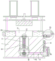
Referring to fig. 1-6, an injection mold is used in processing of plastic part, including injection mold body 1, is equipped with injection mold groove 2 on the injection mold body 1, is equipped with actuating mechanism on the right-hand member lateral wall of injection mold body 1, and actuating mechanism includes servo motor 4 and the cover body 5 of fixed mounting on the lateral wall of injection mold body 1 right-hand member, and servo motor 4's model is: MSME-5AZS1, servo motor 4 is used for driving the rotation of the first gear 7 in the pivot 6, cover body 5 is used for servo motor 4, and the first gear 7 and the second gear 11 of meshing provide the protection, servo motor 4 is located cover body 5, fixedly connected with pivot 6 in servo motor 4's the drive shaft, the first gear 7 of coaxial fixedly connected with in the pivot 6, first gear 7 is connected with the driving medium transmission, fixed mounting has controller 8 on the right-hand member lateral wall of injection mold body 1, controller 8's model is: KY02S-MAM-100, controller 8 is used for controlling the opening and closing of servo motor 4, and controller 8 is electrically connected with servo motor 4.
Be equipped with cavity 3 in injection mold body 1, cavity 3 is close to the right side inner wall of bottom and goes up the level and rotate and run through and be equipped with the driving medium, the driving medium sets up including the intercommunication and leads to the groove 9 in injection mold 2 is close to the circular on the right side inner wall of bottom, it is connected with worm 10 to rotate on injection mold 2's the left side inner wall, worm 10's right-hand member level runs through circular logical groove 9 and sets up and is connected with the inner wall rotation of the cover body 5, worm 10 is located one of the cover body 5 and serves coaxial fixedly connected with second gear 11, first gear 7 meshes with second gear 11, first gear 7 rotates and drives the second gear 11 rotation of meshing, and the worm 10 that drives coaxial coupling by second gear.
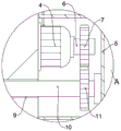
The bottom of the cavity 3 is rotatably connected with an ejection mechanism, the ejection mechanism penetrates through the bottom of the injection mold groove 2, the driving mechanism and the ejection mechanism are in transmission connection with a transmission part, the ejection mechanism comprises a threaded rod 12 which is rotatably connected to the bottom of the cavity 3, a worm wheel 13 is coaxially and fixedly connected to the threaded rod 12, the worm wheel 13 is meshed with a worm 10, the worm 10 rotates to drive the meshed worm wheel 13 to rotate, and the worm wheel 13 drives the coaxially connected threaded rod 12 to rotate, the threaded rod 12 is in threaded sleeve connection with the lifting block 14, the lifting block 14 is in sliding connection with the inner walls of the left side and the right side of the cavity 3, the upper end of the lifting block 14 is fixedly connected with a lifting sleeve 15, the lifting block 14 is matched with the lifting sleeve 15 to eject out a forming mold in the injection mold cavity 2, the lifting sleeve 15 is in sleeve connection with the threaded rod 12, and the upper end of the lifting sleeve 15 penetrates through the bottom of the injection mold cavity 2 located at the central position.
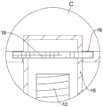
All be equipped with spout 16 on the left and right sides inner wall of cavity 3, equal sliding connection has assorted slider 17 with it in two spout 16, spout 16's one end is kept away from respectively with elevator 14 both ends lateral wall fixed connection about to two slider 17, slider 17 when removing in spout 16, can prevent that threaded rod 12 from rotating elevator 14 that drives the screw thread and cup joint and rotate simultaneously, and restriction elevator 14 and the 15 lifting range of lifting sleeve, be equipped with ring channel 18 on the bottom of the die cavity 2 of moulding plastics, the interpolation of ring channel 18 is equipped with ring packing 19, lifting sleeve 15 runs through ring packing 19 and sets up, ring packing 19 can prevent to mould plastics in the raw materials flows into cavity 3.
This internal circulative cooling mechanism that is equipped with of injection mold, circulative cooling mechanism encircles the setting of injection mold groove 2, circulative cooling mechanism is including setting up annular cavity 20 and the backup pad 21 of fixed connection on the 1 right-hand member lateral wall of injection mold body in injection mold body 1 respectively, annular cavity 20 encircles the setting of injection mold groove 2, the intussuseption of annular cavity 20 is filled with the coolant liquid, the coolant liquid is used for cooling the forming die in the injection mold groove 2, the upper end of backup pad 21 has circulating pump 22 and tube cooler 23 from a left side to the right side fixed mounting in proper order, circulating pump 22 is used for cooling the coolant liquid after rising temperature in the annular cavity 20 via tube cooler 23, cooperation pipe 24 realizes that the coolant liquid in the annular cavity 20 carries out circulative cooling to the forming die in the injection mold groove 2, circulating pump 22's model is: MPH-18CV-5D, the model of the tube cooler 23 is: AES500-1.6-40-4I, the input of circulating pump 22 and the annular cavity 20 near the annular inner wall of bottom intercommunication set up, the output of circulating pump 22 and the input of tube cooler 23 intercommunication set up, the output of tube cooler 23 intercommunication is provided with pipe 24, pipe 24 is used for the circulation of cooling liquid in annular cavity 20, the one end that pipe 24 kept away from tube cooler 23 and the annular cavity 20 near the annular inner wall intercommunication set up of bottom, the one end fixed mounting that pipe 24 is close to tube cooler 23 has governing valve 25, the model of governing valve 25 is: 020ZXP-Q10BLS1-SEXP, with valve 25 being used to control the flow of liquid within catheter 24.
When the invention is used, when a mold in an injection mold cavity 2 is formed, a cooling liquid in an annular cavity 20 cools a forming mold in the injection mold cavity 2, the cooling liquid heated in the annular cavity 20 is cooled by a circulating pump 22 through a tubular cooler 23, the cooling liquid in the annular cavity 20 is matched with a conduit 24 to realize the circulating cooling of the cooling liquid in the annular cavity 20 on the forming mold in the injection mold cavity 2, the cooling efficiency of the forming mold is improved, after the mold in the injection mold cavity 2 is formed, a servo motor 4 in a cover body 5 is started by a controller 8 to drive a first gear 7 on a rotating shaft 6 to rotate, so that the first gear 7 drives a second gear 11 meshed with the first gear to rotate, and the second gear 11 drives a worm 10 coaxially connected with the worm to rotate, so that the worm 10 drives a worm wheel 13 meshed with the worm wheel 13 to rotate, thereby the worm wheel 13 drives a threaded rod 12 coaxially connected with the worm wheel to rotate, at this time, the rotating threaded rod 12 drives the lifting block 14 in threaded sleeve joint to lift under the limiting effect of the sliding groove 16 and the sliding block 17, so that the lifting block 14 is matched with the lifting sleeve 15 to eject a forming mold in the injection molding mold cavity 2, the mold after injection molding is conveniently taken out, and the mold is retracted into the annular groove 18 after ejection, and subsequent ejection operation is conveniently and smoothly carried out.
The above description is only for the preferred embodiment of the present invention, but the scope of the present invention is not limited thereto, and any person skilled in the art should be considered to be within the technical scope of the present invention, and the technical solutions and the inventive concepts thereof according to the present invention should be equivalent or changed within the scope of the present invention.
Claims (6)
1. An injection mold for processing plastic parts comprises an injection mold body (1), wherein an injection mold groove (2) is formed in the injection mold body (1), and the injection mold is characterized in that a driving mechanism is arranged on the side wall of the right end of the injection mold body (1), a cavity (3) is arranged in the injection mold body (1), a driving part is horizontally and rotatably arranged on the inner wall of the right side, close to the bottom, of the cavity (3) in a penetrating manner, an ejection mechanism is rotatably connected to the bottom of the cavity (3) and penetrates through the bottom of the injection mold groove (2), the driving mechanism and the ejection mechanism are both in transmission connection with the driving part, a circulating cooling mechanism is arranged in the injection mold body (1) and surrounds the injection mold groove (2), and the driving mechanism comprises a servo motor (4) and a cover body (5) which are fixedly arranged on the side wall of the right end of the injection mold body (1), servo motor (4) are located the cover body (5), fixedly connected with pivot (6) in the drive shaft of servo motor (4), first gear (7) of coaxial fixedly connected with are gone up in pivot (6), first gear (7) are connected with the driving medium transmission, fixed mounting has controller (8) on the right-hand member lateral wall of injection mold body (1), controller (8) are connected with servo motor (4) electricity.
2. The injection mold for processing the plastic part as recited in claim 1, wherein the transmission member comprises a circular through groove (9) which is communicated with and arranged on the inner wall of the injection mold groove (2) close to the right side of the bottom, a worm (10) is rotatably connected to the inner wall of the left side of the injection mold groove (2), the right end of the worm (10) horizontally penetrates through the circular through groove (9) and is rotatably connected with the inner wall of the cover body (5), a second gear (11) is coaxially and fixedly connected to one end of the worm (10) located in the cover body (5), and the first gear (7) is meshed with the second gear (11).
3. The injection mold for processing the plastic part as claimed in claim 2, wherein the ejection mechanism comprises a threaded rod (12) rotatably connected to the bottom of the cavity (3), a worm wheel (13) is coaxially and fixedly connected to the threaded rod (12), the worm wheel (13) is meshed with the worm (10), an elevating block (14) is sleeved on the threaded rod (12) in a threaded manner, the elevating block (14) is slidably connected with the inner walls of the left side and the right side of the cavity (3), an elevating sleeve (15) is fixedly connected to the upper end of the elevating block (14), the elevating sleeve (15) is sleeved on the threaded rod (12), and the upper end of the elevating sleeve (15) penetrates through the bottom of the injection mold groove (2) located at the central position.
4. An injection mold for processing plastic parts according to claim 3, wherein the inner walls of the left and right sides of the cavity (3) are provided with sliding grooves (16), the two sliding grooves (16) are connected with sliding blocks (17) matched with the sliding grooves in a sliding manner, and one ends of the two sliding blocks (17) far away from the sliding grooves (16) are respectively fixedly connected with the side walls of the left and right ends of the lifting block (14).
5. An injection mold for processing plastic parts according to claim 3, wherein the bottom of the injection mold cavity (2) is provided with an annular groove (18), an annular sealing ring (19) is inserted into the annular groove (18), and the lifting sleeve (15) is arranged to penetrate through the annular sealing ring (19).
6. The injection mold for processing the plastic part as claimed in claim 1, wherein the circulating cooling mechanism comprises an annular cavity (20) and a support plate (21), the annular cavity (20) is respectively arranged in the injection mold body (1), the support plate (21) is fixedly connected to the side wall of the right end of the injection mold body (1), the annular cavity (20) is arranged around the injection mold cavity (2), the annular cavity (20) is filled with cooling liquid, a circulating pump (22) and a tubular cooler (23) are fixedly arranged on the upper end of the support plate (21) from left to right in sequence, the input end of the circulating pump (22) is communicated with the annular inner wall of the annular cavity (20) close to the bottom, the output end of the circulating pump (22) is communicated with the input end of the tubular cooler (23), the output end of the tubular cooler (23) is communicated with a guide pipe (24), one end of the guide pipe (24) far away from the tubular cooler (23) is communicated with the annular inner wall of the annular cavity (20) close to the bottom, and an adjusting valve (25) is fixedly mounted at one end of the guide pipe (24) close to the tubular cooler (23).
Priority Applications (1)
| Application Number | Priority Date | Filing Date | Title |
|---|---|---|---|
| CN202010481163.1A CN111775419A (en) | 2020-05-31 | 2020-05-31 | Injection mold is used in processing of plastic part |
Applications Claiming Priority (1)
| Application Number | Priority Date | Filing Date | Title |
|---|---|---|---|
| CN202010481163.1A CN111775419A (en) | 2020-05-31 | 2020-05-31 | Injection mold is used in processing of plastic part |
Publications (1)
| Publication Number | Publication Date |
|---|---|
| CN111775419A true CN111775419A (en) | 2020-10-16 |
Family
ID=72754514
Family Applications (1)
| Application Number | Title | Priority Date | Filing Date |
|---|---|---|---|
| CN202010481163.1A Pending CN111775419A (en) | 2020-05-31 | 2020-05-31 | Injection mold is used in processing of plastic part |
Country Status (1)
| Country | Link |
|---|---|
| CN (1) | CN111775419A (en) |
Cited By (3)
| Publication number | Priority date | Publication date | Assignee | Title |
|---|---|---|---|---|
| CN112536981A (en) * | 2020-11-20 | 2021-03-23 | 朱晔 | Injection mold |
| CN112622122A (en) * | 2021-01-06 | 2021-04-09 | 黄妃成 | Cooling device is used in plastic mould processing |
| CN112848097A (en) * | 2020-12-21 | 2021-05-28 | 李元义 | Injection mold for producing injection molding pipe |
Citations (6)
| Publication number | Priority date | Publication date | Assignee | Title |
|---|---|---|---|---|
| CN205202048U (en) * | 2015-11-06 | 2016-05-04 | 百利盖(昆山)有限公司 | A cooling body for bottle lid mould |
| CN108995151A (en) * | 2018-10-15 | 2018-12-14 | 滁州市志航精密模具科技有限公司 | Injection mold for refrigerator |
| CN210211253U (en) * | 2019-03-13 | 2020-03-31 | 新昌县双彩乡亚飞轴承厂 | Quick mould cooling equipment |
| CN210280616U (en) * | 2019-04-13 | 2020-04-10 | 苏州巨模模具有限公司 | Novel metal die-casting die |
| CN210453535U (en) * | 2019-07-10 | 2020-05-05 | 杭州萧山忠荣模具厂 | Mould with convenient ejecting device |
| CN210501244U (en) * | 2019-07-19 | 2020-05-12 | 北京市顺嘉塑料厂 | Mold ejection system for generator winding bone |
-
2020
- 2020-05-31 CN CN202010481163.1A patent/CN111775419A/en active Pending
Patent Citations (6)
| Publication number | Priority date | Publication date | Assignee | Title |
|---|---|---|---|---|
| CN205202048U (en) * | 2015-11-06 | 2016-05-04 | 百利盖(昆山)有限公司 | A cooling body for bottle lid mould |
| CN108995151A (en) * | 2018-10-15 | 2018-12-14 | 滁州市志航精密模具科技有限公司 | Injection mold for refrigerator |
| CN210211253U (en) * | 2019-03-13 | 2020-03-31 | 新昌县双彩乡亚飞轴承厂 | Quick mould cooling equipment |
| CN210280616U (en) * | 2019-04-13 | 2020-04-10 | 苏州巨模模具有限公司 | Novel metal die-casting die |
| CN210453535U (en) * | 2019-07-10 | 2020-05-05 | 杭州萧山忠荣模具厂 | Mould with convenient ejecting device |
| CN210501244U (en) * | 2019-07-19 | 2020-05-12 | 北京市顺嘉塑料厂 | Mold ejection system for generator winding bone |
Cited By (4)
| Publication number | Priority date | Publication date | Assignee | Title |
|---|---|---|---|---|
| CN112536981A (en) * | 2020-11-20 | 2021-03-23 | 朱晔 | Injection mold |
| CN112848097A (en) * | 2020-12-21 | 2021-05-28 | 李元义 | Injection mold for producing injection molding pipe |
| CN112848097B (en) * | 2020-12-21 | 2022-11-25 | 青岛佳友模具科技有限公司 | Injection mold for producing injection molding pipe |
| CN112622122A (en) * | 2021-01-06 | 2021-04-09 | 黄妃成 | Cooling device is used in plastic mould processing |
Similar Documents
| Publication | Publication Date | Title |
|---|---|---|
| CN111775419A (en) | Injection mold is used in processing of plastic part | |
| CN211993961U (en) | Plastic toy injection mold | |
| CN109130080B (en) | Servo energy-saving injection molding machine that stability is good | |
| CN111168955A (en) | Plastic worm injection molding mold | |
| CN212422088U (en) | Spiral water cooling device for plastic mold | |
| CN115401863A (en) | Environment-friendly energy-saving injection mold | |
| CN214056268U (en) | Large-scale garbage bin injection mold of high-efficient refrigerated high strength | |
| CN109501114A (en) | A kind of high precision Shooting Technique and injection molding machine | |
| CN211279540U (en) | Adjustable injection mold | |
| CN220464657U (en) | Injection molding machine for molding thermos flask liner | |
| CN212045725U (en) | Long-life injection mold | |
| CN212171133U (en) | Mold core guide structure for plastic mold | |
| CN213830117U (en) | Mainframe box mould integrated board | |
| CN112622122A (en) | Cooling device is used in plastic mould processing | |
| CN214239425U (en) | Injection mold auxiliary device of convenient regulation | |
| CN214491308U (en) | Injection molding device with rapid heat dissipation function for tableware processing | |
| CN111251527B (en) | Material taking equipment for die manufacturing products | |
| CN219405359U (en) | Extruder is used in production of encapsulation mould film wetting adhesive tape | |
| CN216831957U (en) | Injection molding machine with automatic demolding function and used for machining parts with internal threads | |
| CN113334717B (en) | Cooling device of annular plastic mold | |
| CN219133058U (en) | Injection mold for internal thread plastic products | |
| CN214645465U (en) | Injection mold convenient to drawing of patterns | |
| CN113733483A (en) | Extrusion molding device for air conditioner shell | |
| CN219466478U (en) | Device for producing sanitary ware | |
| CN218286495U (en) | Double-color injection molding machine for producing fuse box |
Legal Events
| Date | Code | Title | Description |
|---|---|---|---|
| PB01 | Publication | ||
| PB01 | Publication | ||
| SE01 | Entry into force of request for substantive examination | ||
| SE01 | Entry into force of request for substantive examination | ||
| RJ01 | Rejection of invention patent application after publication | ||
| RJ01 | Rejection of invention patent application after publication |
Application publication date: 20201016 |