CN111760106A - Household peritoneal dialysis auxiliary system and docking method - Google Patents
Household peritoneal dialysis auxiliary system and docking method Download PDFInfo
- Publication number
- CN111760106A CN111760106A CN202010766878.1A CN202010766878A CN111760106A CN 111760106 A CN111760106 A CN 111760106A CN 202010766878 A CN202010766878 A CN 202010766878A CN 111760106 A CN111760106 A CN 111760106A
- Authority
- CN
- China
- Prior art keywords
- bin body
- dialysis
- sleeve
- sealing
- central bin
- Prior art date
- Legal status (The legal status is an assumption and is not a legal conclusion. Google has not performed a legal analysis and makes no representation as to the accuracy of the status listed.)
- Pending
Links
Images


Classifications
-
- A—HUMAN NECESSITIES
- A61—MEDICAL OR VETERINARY SCIENCE; HYGIENE
- A61M—DEVICES FOR INTRODUCING MEDIA INTO, OR ONTO, THE BODY; DEVICES FOR TRANSDUCING BODY MEDIA OR FOR TAKING MEDIA FROM THE BODY; DEVICES FOR PRODUCING OR ENDING SLEEP OR STUPOR
- A61M1/00—Suction or pumping devices for medical purposes; Devices for carrying-off, for treatment of, or for carrying-over, body-liquids; Drainage systems
- A61M1/14—Dialysis systems; Artificial kidneys; Blood oxygenators ; Reciprocating systems for treatment of body fluids, e.g. single needle systems for hemofiltration or pheresis
- A61M1/28—Peritoneal dialysis ; Other peritoneal treatment, e.g. oxygenation
-
- A—HUMAN NECESSITIES
- A61—MEDICAL OR VETERINARY SCIENCE; HYGIENE
- A61L—METHODS OR APPARATUS FOR STERILISING MATERIALS OR OBJECTS IN GENERAL; DISINFECTION, STERILISATION OR DEODORISATION OF AIR; CHEMICAL ASPECTS OF BANDAGES, DRESSINGS, ABSORBENT PADS OR SURGICAL ARTICLES; MATERIALS FOR BANDAGES, DRESSINGS, ABSORBENT PADS OR SURGICAL ARTICLES
- A61L2/00—Methods or apparatus for disinfecting or sterilising materials or objects other than foodstuffs or contact lenses; Accessories therefor
- A61L2/16—Methods or apparatus for disinfecting or sterilising materials or objects other than foodstuffs or contact lenses; Accessories therefor using chemical substances
- A61L2/18—Liquid substances or solutions comprising solids or dissolved gases
-
- A—HUMAN NECESSITIES
- A61—MEDICAL OR VETERINARY SCIENCE; HYGIENE
- A61L—METHODS OR APPARATUS FOR STERILISING MATERIALS OR OBJECTS IN GENERAL; DISINFECTION, STERILISATION OR DEODORISATION OF AIR; CHEMICAL ASPECTS OF BANDAGES, DRESSINGS, ABSORBENT PADS OR SURGICAL ARTICLES; MATERIALS FOR BANDAGES, DRESSINGS, ABSORBENT PADS OR SURGICAL ARTICLES
- A61L2/00—Methods or apparatus for disinfecting or sterilising materials or objects other than foodstuffs or contact lenses; Accessories therefor
- A61L2/16—Methods or apparatus for disinfecting or sterilising materials or objects other than foodstuffs or contact lenses; Accessories therefor using chemical substances
- A61L2/20—Gaseous substances, e.g. vapours
- A61L2/202—Ozone
-
- A—HUMAN NECESSITIES
- A61—MEDICAL OR VETERINARY SCIENCE; HYGIENE
- A61L—METHODS OR APPARATUS FOR STERILISING MATERIALS OR OBJECTS IN GENERAL; DISINFECTION, STERILISATION OR DEODORISATION OF AIR; CHEMICAL ASPECTS OF BANDAGES, DRESSINGS, ABSORBENT PADS OR SURGICAL ARTICLES; MATERIALS FOR BANDAGES, DRESSINGS, ABSORBENT PADS OR SURGICAL ARTICLES
- A61L2202/00—Aspects relating to methods or apparatus for disinfecting or sterilising materials or objects
- A61L2202/20—Targets to be treated
- A61L2202/24—Medical instruments, e.g. endoscopes, catheters, sharps
-
- A—HUMAN NECESSITIES
- A61—MEDICAL OR VETERINARY SCIENCE; HYGIENE
- A61M—DEVICES FOR INTRODUCING MEDIA INTO, OR ONTO, THE BODY; DEVICES FOR TRANSDUCING BODY MEDIA OR FOR TAKING MEDIA FROM THE BODY; DEVICES FOR PRODUCING OR ENDING SLEEP OR STUPOR
- A61M1/00—Suction or pumping devices for medical purposes; Devices for carrying-off, for treatment of, or for carrying-over, body-liquids; Drainage systems
- A61M1/14—Dialysis systems; Artificial kidneys; Blood oxygenators ; Reciprocating systems for treatment of body fluids, e.g. single needle systems for hemofiltration or pheresis
- A61M1/16—Dialysis systems; Artificial kidneys; Blood oxygenators ; Reciprocating systems for treatment of body fluids, e.g. single needle systems for hemofiltration or pheresis with membranes
- A61M1/168—Sterilisation or cleaning before or after use
-
- A—HUMAN NECESSITIES
- A61—MEDICAL OR VETERINARY SCIENCE; HYGIENE
- A61M—DEVICES FOR INTRODUCING MEDIA INTO, OR ONTO, THE BODY; DEVICES FOR TRANSDUCING BODY MEDIA OR FOR TAKING MEDIA FROM THE BODY; DEVICES FOR PRODUCING OR ENDING SLEEP OR STUPOR
- A61M2202/00—Special media to be introduced, removed or treated
- A61M2202/04—Liquids
- A61M2202/0413—Blood
Landscapes
- Health & Medical Sciences (AREA)
- Animal Behavior & Ethology (AREA)
- Veterinary Medicine (AREA)
- Public Health (AREA)
- General Health & Medical Sciences (AREA)
- Life Sciences & Earth Sciences (AREA)
- Epidemiology (AREA)
- Chemical & Material Sciences (AREA)
- General Chemical & Material Sciences (AREA)
- Chemical Kinetics & Catalysis (AREA)
- Emergency Medicine (AREA)
- Urology & Nephrology (AREA)
- Heart & Thoracic Surgery (AREA)
- Vascular Medicine (AREA)
- Engineering & Computer Science (AREA)
- Anesthesiology (AREA)
- Biomedical Technology (AREA)
- Hematology (AREA)
- External Artificial Organs (AREA)
Abstract
The invention relates to a household peritoneal dialysis auxiliary system and a butt joint method, the auxiliary system comprises a butt joint operation bin and an auxiliary dialysis table, a gas collection box is arranged below the auxiliary dialysis table, ozone with certain concentration is injected into a central bin body, a supporting tire bead and a supporting gas strip through an inflator pump, the inflation direction is one-way, the shape of the bin body can be ensured not to collapse and deform in the butt joint pipeline and the dialysis liquid exchange process, the internal gas can be ensured not to be in convective exchange with the external gas, so that the infection risk is reduced, a disinfection sleeve is arranged at an inlet port of a dialysis tube joint, a disinfection sponge sleeve is arranged in the disinfection sleeve, the surface wiping disinfection is carried out through the sleeve in the insertion process of the dialysis tube joint, the insertion process is a surface disinfection process, the infection risk is reduced, sealing flap valves with elastic sector slice structures are arranged at the inlet port of the dialysis tube joint and an inlet port, the tube wall can be sealed after the tube head is put into the bin, convection of gas in the bin and gas outside the bin is reduced, and infection risk is reduced.
Description
Technical Field
The invention relates to the technical field of medical instruments, in particular to a household peritoneal dialysis auxiliary system and a docking method.
Background
Peritoneal dialysis is a dialysis mode which utilizes the peritoneum of a human body as a dialysis membrane, exchanges solute and moisture by dialysate filled into the peritoneal cavity and plasma components in capillary vessels on the other side of the peritoneum, removes retention metabolites and excessive moisture in the body, supplements substances required by the body by the dialysate, and achieves the aim of kidney substitution or supporting treatment by continuously updating the peritoneal dialysate; a patient who needs to carry out peritoneal dialysis needs to put a dialysis tube into the body of the patient through a surgical operation, the tube opening of the dialysis tube is positioned outside the body, the peritoneal dialysis can be carried out by butting the dialysis tube with a dialysis liquid tube of a dialysis liquid storage device, dust and bacteria in the air easily enter the body during butting to cause infection, and complications such as peritonitis and the like are caused, so that the patient needs to carry out peritoneal dialysis in a clean, sterilized and disinfected space, the harsh sterile condition is difficult to achieve in a household environment, equipment which can meet the requirement of the condition is not available at present, the patient is required to go to a designated medical place for peritoneal dialysis, the burden on the body and the mind of the patient is increased while medical resources are occupied, the treatment cost of the patient is increased, meanwhile, a plurality of inconveniences are brought to the patient, and the moving range of the patient during treatment is greatly limited, the normal work and life of the patient are seriously affected, and therefore, the above problems need to be solved for those skilled in the art.
Disclosure of Invention
In order to solve the problems, the invention provides a household peritoneal dialysis auxiliary system and a docking method.
The specific contents are as follows: domestic peritoneal dialysis auxiliary system, including butt joint operation storehouse and supplementary dialysis table, characterized by:
the butt joint operation bin comprises a central bin body of an air bag structure, and a support tire bead and a support air strip which are respectively arranged at the end part and the side surface of the central bin body, wherein the components are all made of soft plastic films;
the central bin body is hollow and sealed cylindrical, two ends of the central bin body are respectively provided with an extension section which is inwards turned into a horn shape, the outer end of each extension section is correspondingly and hermetically connected with the end part of the central bin body, the inner end of each extension section is hermetically connected with the neck part of an operation glove in the central bin body, the interior of the operation glove is communicated with the outside, two ends of the central bin body are respectively provided with a circular support bead, the edge of the end part of the central bin body is fixed on the corresponding support bead, the central bin body and the support beads are coaxial, a communication pipe for communicating the internal spaces of the central bin body and the support beads is arranged between each support bead and the central bin body, a first one-way duckbill valve is arranged in the communication pipe, the flow direction in the first one-way duckbill valve is only limited from the interior of the central bin body to the interior of the support beads, and N support air, n is more than or equal to 3, each supporting air strip is hollow and is arranged along the bus direction of the central bin body, and two ends of each supporting air strip are respectively fixed and communicated with supporting tire beads at two ends of the central bin body;
the sterilizing device is characterized in that a sterilizing sleeve extending into the central bin body is further arranged on the central bin body, the plastic hardness of the sterilizing sleeve is greater than that of the central bin body, the sterilizing sleeve can keep the shape of the sterilizing sleeve, the edge of the outer end of the sterilizing sleeve is fixed on a positioning sheet and is communicated with the outside, the positioning sheet is fixedly attached to the outer surface of the central bin body in a sealing mode, an elastic first sealing flap valve which is circular in shape as a whole is arranged on the inner end face of the sterilizing sleeve, the first sealing flap valve is of a plurality of fan-shaped valve flap structures formed by radial cutting seams from the center to the circumference, a cylindrical sponge sleeve matched with the sterilizing sleeve is arranged inside the sterilizing sleeve, disinfectant is absorbed in the sponge sleeve, a plurality of fan-shaped sponge pieces matched with the shape of the first sealing flap valve are arranged on the lower end face of the sponge sleeve, and a first sealing paste; the sponge sleeve comprises a cylindrical outer cotton body, the outer cotton body is fixed on the inner circumferential surface of the disinfection sleeve, a plurality of inner cotton cylinders are uniformly distributed in the outer cotton body along the circumferential direction of the outer cotton body, each inner cotton cylinder is arranged along the parallel direction of a bus of the outer cotton body, a gap is formed between every two adjacent inner cotton cylinders, the inner cotton cylinders are as long as the outer cotton body and are fixedly connected together through supporting cotton bodies arranged along the radial direction, and disinfection liquid is soaked in the whole sponge sleeve; the central bin body is also provided with an elastic second sealing flap valve which is round as a whole, the shape of the second sealing flap valve is the same as that of the first sealing flap valve, the outer end of the second sealing flap valve is provided with a second sealing paste pasted on the central bin body, the central bin body is provided with an air inlet pipe communicated with the outside, a second one-way duckbill valve is arranged inside the air inlet pipe, and the flow direction in the second one-way duckbill valve is limited to be from the outside to the inside of the central bin body;
the auxiliary dialysis table comprises an operation table supported by a stand column, a retainer fixed on the table top of the operation table, a gas collection box arranged below the operation table, an inflator pump and a high-voltage discharge ozone machine which are fixed in the gas collection box, wherein the volume in the gas collection box is larger than that of the butt joint operation bin;
the holder comprises two positioning rings which are symmetrically arranged at the left and the right, each positioning ring is vertically fixed on the table top of the operating table through a bracket, the outline of the positioning ring is matched with the outline of a supporting tire bead, a bearing strip with the shape of a circular arc cross section is connected between the end surfaces at the lower parts of the two positioning rings, the inflator pump is fixed on the side wall inside the gas collecting box, an inflation tube on the inflator pump penetrates through the box body of the gas collecting box and is arranged on the table top of the operating table, a connector matched with an air inlet tube is arranged at the free end of the inflation tube, the high-pressure discharge type ozone machine is fixed at the bottom of the gas collecting box, a power cord plug of the high-pressure discharge type ozone machine is arranged outside the gas collecting box, the gas collecting box is designed in a sealing mode, the volume of the gas collecting box is far larger than that of the butt joint, the inner side surface of the sealing door is provided with an annular sealing strip, the sealing door is also hinged with a stop strip for locking the sealing door, and the outer side wall of the gas collection box is fixed with a clamping block correspondingly matched with the stop strip.
Preferably, the positioning piece is provided with two first tearing grooves which are symmetrical and extend outwards from the edge of the port on the disinfection sleeve, the central bin body is provided with a second tearing groove corresponding to the first tearing groove, the disinfection sleeve is provided with a third tearing groove aligned with the first tearing groove along the bus direction of the disinfection sleeve, and the outer surface of the sponge sleeve is provided with a fourth tearing groove which is arranged along the bus direction of the disinfection sleeve and corresponds to the third tearing groove.
Preferably, the inside of the central storehouse body is provided with a storage box with an upper opening, a brand new iodophor cap is placed in the storage box, and a third sealing sticker is pasted on the opening surface of the storage box.
Preferably, the outer surface of the positioning plate is fixed with a raised handheld gripping lug which at least comprises two pieces and is symmetrical about the first tearing groove.
Preferably, the number of the supporting air bars is N =3, and a handle is further fixed on the sealing door.
Preferably, the cross section of the supporting tire bead is circular, and the cross section of the supporting air bar is semicircular.
Preferably, the volume of the interior of the gas collecting box is not less than 5 times of the volume of the butt joint operation cabin.
Preferably, a vertical suspension rod is fixed on the table top of the operating table, and a hook is fixed on the suspension rod.
Preferably, the inflation pipe is connected with a pressure regulating overflow valve in parallel, and the pressure regulating overflow valve is positioned in the gas collecting box.
A method for docking a dialysis liquid tube by using the household peritoneal dialysis auxiliary system, which comprises the following steps:
opening a sealing door to enable the internal pressure and the external pressure of a gas collection box to be equal, clamping a stop strip on the sealing door on a clamping block, and sealing an installation opening through the sealing door and the sealing strip;
secondly, switching on a power supply of the high-voltage discharge type ozone machine, starting the high-voltage discharge type ozone machine to work and gradually converting oxygen in the gas collecting box into ozone, and closing the high-voltage discharge type ozone machine after the high-voltage discharge type ozone machine works to a rated time, namely the ozone in the gas collecting box reaches a rated concentration;
unsealing the butt joint operation cabin and placing the butt joint operation cabin on a holding frame, sealing and communicating an inflation tube with an air inlet pipe on a central cabin body through a connector at the end part of the inflation tube, starting an inflation pump to inject ozone gas in a gas collection box into the central cabin body, and enabling the ozone gas to enter a support tire bead and a support gas bar through a first one-way duckbill valve after the ozone gas in the central cabin body reaches a certain pressure;
fourthly, after the supporting tire beads and the supporting air strips are completely supported and molded by the internal air, the whole butt joint operation cabin is limited by the retainer, then the inflation tube is disconnected with the air inlet tube of the central cabin body, and the first duckbill valve and the second duckbill valve are closed to keep the shape of the butt joint operation cabin;
the first sealing paste on the outer port of the disinfection sleeve is torn off, a dialysis tube joint carried on the body of a patient is slowly inserted into the disinfection sleeve, the dialysis tube joint can extrude the inner cotton cylinder outwards after being inserted into the sponge sleeve, a gap is formed between the inner cotton cylinders, the contact surface between the inner cotton cylinder and the surface of the dialysis tube joint can be increased after the inner cotton cylinder is extruded, the surface of the dialysis tube joint can be better disinfected, meanwhile, the sponge sleeve cannot be torn due to expansion in the process of inserting the dialysis tube joint, the part of the dialysis tube joint, which is leaked to be cleaned, is avoided, the comprehensive performance and reliability of disinfection of the dialysis tube joint are increased, the dialysis tube joint gradually penetrates through the first sealing flap valve and extends into the central bin body, disinfection and warehousing are completed, and the plurality of fan-shaped valve flaps of the first sealing flap valve are propped open and then rebound to cling to the outer;
tearing off a second sealing paste at the outer port of the second sealing flap valve, enabling the pipe joint of the dialysate bag to penetrate through the second sealing flap valve and extend into the central bin body, and enabling a plurality of fan-shaped valve clacks of the second sealing flap valve to rebound and cling to the outer surface of the dialysate bag pipe after being unfolded;
both hands of an operator extend into the corresponding operating gloves from the two ends of the central bin body respectively;
manually screwing down the iodophor caps on the pipe joint of the dialysis pipe and the pipe joint of the dialysate bag respectively;
ninthly, correspondingly screwing the dialysis pipe joint and the dialysis liquid bag pipe joint together, completing butt joint, hanging the dialysis liquid bag on a hook hanging the rod, and carrying out peritoneal dialysis.
The invention has the beneficial technical effects that:
1. the butt joint operation cabin is of an air bag structure, is in a compressed state before being unsealed, is convenient to carry, and keeps stable in shape after being inflated and formed.
2. The high-pressure discharge type ozone machine is arranged in the gas collection box, ozone with a certain concentration can be generated in the gas collection box, the concentration of the ozone filled in the central bin body is ensured, the sterilization effect is ensured, and the ozone cannot leak.
3. In the invention, gas firstly enters the central bin body, after the central bin body is filled, the gas is refilled and enters the supporting tire beads and the supporting air strips at two ends, the inflating process is unidirectional, and the gas entering the supporting tire beads and the supporting air strips can only enter and cannot be discharged, so that the shape of the central bin body can be ensured not to collapse and deform in the processes of butt joint of pipelines and dialysis liquid exchange, and the internal gas can be ensured not to be in convective exchange with the external gas, thereby reducing the infection risk.
4. The disinfection sleeve is arranged at the inlet of the dialysis tube joint, the sponge sleeve containing disinfectant is arranged in the disinfection sleeve, the surface of the dialysis tube joint is wiped and disinfected through the sponge sleeve in the insertion process, the non-disinfection habit of a patient during self operation is changed, and the surface disinfection process is the dialysis tube joint insertion process, so that the infection risk is reduced.
5. According to the invention, the inlet of the dialysis tube joint and the inlet of the other dialysis bag tube joint are provided with the elastic sealing flap valves with the fan-shaped slicing structures, so that the tube wall can be sealed after the tube joints enter the central bin body, the convection between the gas in the bin body and the gas outside the bin body is reduced to the greatest extent, and the infection risk is reduced.
6. The air source of the invention adopts ozone, firstly, the ozone can carry out secondary disinfection on the central bin body and can also carry out secondary disinfection on the inserted dialysis pipe joint, the decomposed ozone is oxygen, and the ozone has no toxicityThe ozone entering the supporting tire bead and the supporting air strip is decomposed into oxygen and then the volume of the ozone is increased, namely 2O3→3O2And the total number of molecules is increased, so that the gas pressure in the supporting tire bead and the supporting gas strip can be increased, and the shape of the whole central cabin body can be kept.
7. A brand new iodophor cap is arranged in the central bin body, and after peritoneal dialysis is completed, the brand new iodophor cap is directly replaced in the central bin body, so that the central bin body is safe and convenient.
8. The disinfection sleeve part of the invention is of a tearable structure, and can be torn into two halves after use, so that the dialysis pipe joint can exit from the central bin body conveniently, and the butt joint operation bin of the invention can be prevented from being used secondarily.
Drawings
Fig. 1 is a schematic perspective view of a home peritoneal dialysis auxiliary system (the docking operation chamber is in an inflated state);
FIG. 2 is a schematic perspective view of an auxiliary dialysis table;
FIG. 3 is a front sectional view of a gas collection box in the auxiliary dialysis table;
FIG. 4 is a schematic perspective view of the docking operation cabin;
FIG. 5 is a front cross-sectional view of FIG. 4;
FIG. 6 is a front cross-sectional view of FIG. 4 during use;
FIG. 7 is a cross-sectional view taken along line A-A of FIG. 5;
FIG. 8 is a cross-sectional view taken along line B-B of FIG. 7;
FIG. 9 is an enlarged view of C in FIG. 5;
FIG. 10 is an enlarged schematic view of D in FIG. 5;
FIG. 11 is an enlarged view of E in FIG. 5;
FIG. 12 is an enlarged schematic view of F in FIG. 5;
FIG. 13 is an enlarged schematic view of G of FIG. 5;
FIG. 14 is an enlarged view of H in FIG. 5;
FIG. 15 is a schematic perspective view of a sponge cover;
FIG. 16 is a top view of the sponge sleeve;
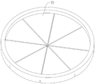
fig. 17 is a schematic perspective view of a first flap valve (a second flap valve);
in the figure: 11. the medical dialysis machine comprises a central cabin body, 14 supporting tire beads, 25 supporting air strips, 12 extending sections, 13 operating gloves, 16 communicating pipes, 161, a first one-way duckbill valve, 15 a disinfection sleeve, 19 a positioning sheet, 31 a first sealing flap valve, 28 a sponge sleeve, 282 a sponge sheet, 19 a first sealing patch, 17 a second sealing flap valve, 18 a second sealing patch, 21 an air inlet pipe, 22 a second one-way duckbill valve, 291 a first tearing groove, 111 a second tearing groove, 151 a third tearing groove, 281 a fourth tearing groove, 285 an outer cotton body, 284 an inner cotton cylinder, 283 a supporting cotton body, 23 a storage box, 24 a brand new iodophor cap, 231 a third sealing patch, 30 a handheld grasping lug, 27 a dialysate bag pipe joint, 26 a dialysate pipe joint, 411 a stand, 40 a butt-joint operating cabin, 41 an operating console, 42 a holding box, 48, 49 and an air pump, 50. The high-voltage discharge ozone machine comprises a high-voltage discharge ozone machine body, 481, a positioning ring, 482 a bracket, 483 a bearing strip, 491 an inflation tube, 492 a connector, 493 a pressure-regulating overflow valve, 501 a power line, 502 a power line plug, 421 a mounting opening, 431, a sealing strip, 43 a sealing door, 45 a blocking strip, 46 a clamping block, 44 a handle, 47 a hanging rod and 471 a hook.
Detailed Description
In a first embodiment, referring to fig. 1-17, a home peritoneal dialysis assistance system includes a docking station and an auxiliary dialysis table;
the butt joint operation bin comprises a central bin body of an air bag structure, and a support tire bead and a support air strip which are respectively arranged at the end part and the side surface of the central bin body, wherein the components are all made of soft plastic films;
the central bin body is hollow and sealed cylindrical, two ends of the central bin body are respectively provided with an extension section which is inwards turned into a horn shape, the outer end of each extension section is correspondingly and hermetically connected with the end part of the central bin body, the inner end of each extension section is hermetically connected with the neck part of an operation glove in the central bin body, the interior of the operation glove is communicated with the outside, two ends of the central bin body are respectively provided with a circular support bead, the edge of the end part of the central bin body is fixed on the corresponding support bead, the central bin body and the support beads are coaxial, a communication pipe for communicating the internal spaces of the central bin body and the support beads is arranged between each support bead and the central bin body, a first one-way duckbill valve is arranged in the communication pipe, the flow direction in the first one-way duckbill valve is only limited from the interior of the central bin body to the interior of the support beads, and N support air, wherein N is greater than or equal to 3, N =3 in this embodiment, each support air strip is an internally hollow strip and is arranged along a bus direction of the central bin body, and two ends of each support air strip are respectively fixed and communicated with support tire beads at two ends of the central bin body; after the central bin body is full of gas, re-filling gas enters the supporting tire beads and the supporting gas strips at the two ends, the inflating process is one-way, the gas entering the supporting tire beads and the supporting gas strips can only enter and cannot be discharged, so that the shape of the central bin body can be ensured not to collapse and deform in the processes of butt joint of pipelines and dialysis liquid exchange, and the internal gas can be ensured not to be in convective exchange with the external gas, thereby reducing the infection risk.
The sterilizing device is characterized in that a sterilizing sleeve extending into the central bin body is further arranged on the central bin body, the plastic hardness of the sterilizing sleeve is greater than that of the central bin body, the sterilizing sleeve can keep the shape of the sterilizing sleeve, the edge of the outer end of the sterilizing sleeve is fixed on a positioning sheet and is communicated with the outside, the positioning sheet is fixedly attached to the outer surface of the central bin body in a sealing mode, an elastic first sealing flap valve which is circular in shape as a whole is arranged on the inner end face of the sterilizing sleeve, the first sealing flap valve is of a plurality of fan-shaped valve flap structures formed by radial cutting seams from the center to the circumference, a cylindrical sponge sleeve matched with the sterilizing sleeve is arranged inside the sterilizing sleeve, disinfectant is absorbed in the sponge sleeve, a plurality of fan-shaped sponge pieces matched with the shape of the first sealing flap valve are arranged on the lower end face of the sponge sleeve, and a first sealing paste; the sponge sleeve comprises a cylindrical outer cotton body, the outer cotton body is fixed on the inner circumferential surface of the disinfection sleeve, a plurality of inner cotton cylinders are uniformly distributed in the outer cotton body along the circumferential direction of the outer cotton body, each inner cotton cylinder is arranged along the parallel direction of a bus of the outer cotton body, a gap is formed between every two adjacent inner cotton cylinders, the inner cotton cylinders are as long as the outer cotton body and are fixedly connected together through supporting cotton bodies arranged along the radial direction, and disinfection liquid is soaked in the whole sponge sleeve; the central bin body is also provided with an elastic second sealing flap valve which is round as a whole, the shape of the second sealing flap valve is the same as that of the first sealing flap valve, the outer end of the second sealing flap valve is provided with a second sealing paste pasted on the central bin body, the central bin body is provided with an air inlet pipe communicated with the outside, a second one-way duckbill valve is arranged inside the air inlet pipe, and the flow direction in the second one-way duckbill valve is limited to be from the outside to the inside of the central bin body;
the auxiliary dialysis table comprises an operation table supported by a stand column, a retainer fixed on the table top of the operation table, a gas collection box arranged below the operation table, an inflator pump and a high-voltage discharge ozone machine which are fixed in the gas collection box, wherein the volume in the gas collection box is larger than that of the butt joint operation bin;
the holder comprises two positioning rings which are symmetrically arranged left and right, each positioning ring is vertically fixed on the table top of the operation table through a support, the contour of the positioning ring is matched with that of a supporting tire bead, a bearing strip with the shape of a circular arc cross section is connected between the end surfaces of the lower parts of the two positioning rings, the inflator pump is fixed on the side wall inside the gas collecting box, an inflation tube on the inflator pump penetrates through the box body of the gas collecting box and is arranged on the table top of the operation table, a connector matched with an air inlet tube is arranged on the free end of the inflation tube, the high-pressure discharge type ozone machine is fixed at the bottom of the gas collecting box, a power cord plug of the high-pressure discharge type ozone machine is arranged outside the gas collecting box, the gas collecting box is designed in a sealing mode, the volume of the gas collecting box is far larger than that of the butt joint operation bin, the side surface of the gas collection box is provided with a mounting opening, a side-opening sealing door is hinged on the mounting opening, an annular sealing strip is arranged on the inner side surface of the sealing door, a stop strip for locking the sealing door is hinged on the sealing door, and a clamping block correspondingly matched with the stop strip is fixed on the outer side wall of the gas collection box. When not in use at ordinary times, the dialysis related articles can be stored in the gas collection box, and the sterilization and disinfection can be carried out by ozone, so that the device is safe and convenient.
The positioning sheet is provided with two first tearing grooves which are symmetrical and extend outwards from the edge of the upper port of the disinfection sleeve, the central bin body is provided with a second tearing groove corresponding to the first tearing groove, the disinfection sleeve is provided with a third tearing groove aligned with the first tearing groove along the bus direction of the disinfection sleeve, and the outer surface of the sponge sleeve is provided with a fourth tearing groove which is arranged along the bus direction of the disinfection sleeve and corresponds to the third tearing groove. The tearing grooves are arranged, so that the whole butt joint operation cabin can be torn into two parts along the tearing grooves after being used, the dialysis pipe joint can conveniently exit from the central cabin body, and meanwhile, the butt joint operation cabin is prevented from being used for the second time.
The inside in the central storehouse body be equipped with upper portion open-ended storage box, placed brand-new iodophor cap in this storage box, the open surface of storage box is pasted and is had the third to seal and paste. After peritoneal dialysis is completed, a dialysis pipe joint is directly replaced with a brand-new iodophor cap in the central bin body, so that the peritoneal dialysis machine is safe and convenient.
The outer surface of the positioning plate is fixed with a raised handheld grabbing ear, and the handheld grabbing ear at least comprises two pieces and is symmetrical about the first tearing groove. The hand-held ear-grasping is convenient to operate and use, and meanwhile, the disinfection sleeve is convenient to tear by force.
The volume of the interior of the gas collection box is not less than 5 times of the volume of the butt joint operation cabin, so that the gas collection box can provide sufficient gas sources.
The cross section of the supporting tire bead is circular, and the cross section of the supporting air bar is semicircular. The whole structure is more smooth and harmonious, the manufacture is convenient, and the use is beautiful.
The sealing door is also fixedly provided with a handle, so that the sealing door can be opened and closed conveniently.
The vertical hanging rod is fixed on the table top of the operating table, and the hook is fixed on the hanging rod and used for hanging a dialysate bag, so that dialysis of a patient is facilitated.
The gas charging pipe is connected with a pressure regulating overflow valve in parallel, and the pressure regulating overflow valve is positioned in the gas collecting box. The pressure regulating overflow valve is arranged to protect the butt joint operation cabin and prevent the butt joint operation cabin from being excessively inflated.
Embodiment two, referring to fig. 1-17, a method for performing dialysate tube docking using the home peritoneal dialysis assistance system of embodiment one, the method comprising the steps of:
opening a sealing door to enable the internal pressure and the external pressure of a gas collection box to be equal, clamping a stop strip on the sealing door on a clamping block, and sealing an installation opening through the sealing door and the sealing strip;
secondly, switching on a power supply of the high-voltage discharge type ozone machine, starting the high-voltage discharge type ozone machine to work and gradually converting oxygen in the gas collecting box into ozone, and closing the high-voltage discharge type ozone machine after the high-voltage discharge type ozone machine works to a rated time, namely the ozone in the gas collecting box reaches a rated concentration;
unsealing the butt joint operation cabin and placing the butt joint operation cabin on a holding frame, sealing and communicating an inflation tube with an air inlet pipe on a central cabin body through a connector at the end part of the inflation tube, starting an inflation pump to inject ozone gas in a gas collection box into the central cabin body, and enabling the ozone gas to enter a support tire bead and a support gas bar through a first one-way duckbill valve after the ozone gas in the central cabin body reaches a certain pressure;
fourthly, after the supporting tire beads and the supporting air strips are completely supported and molded by the internal air, the whole butt joint operation cabin is limited by the retainer, then the inflation tube is disconnected with the air inlet tube of the central cabin body, and the first duckbill valve and the second duckbill valve are closed to keep the shape of the butt joint operation cabin;
the first sealing paste on the outer port of the disinfection sleeve is torn off, a dialysis tube joint carried on the body of a patient is slowly inserted into the disinfection sleeve, the dialysis tube joint can extrude the inner cotton cylinder outwards after being inserted into the sponge sleeve, a gap is formed between the inner cotton cylinders, the contact surface between the inner cotton cylinder and the surface of the dialysis tube joint can be increased after the inner cotton cylinder is extruded, the surface of the dialysis tube joint can be better disinfected, meanwhile, the sponge sleeve cannot be torn due to expansion in the process of inserting the dialysis tube joint, the part of the dialysis tube joint, which is leaked to be cleaned, is avoided, the comprehensive performance and reliability of disinfection of the dialysis tube joint are increased, the dialysis tube joint gradually penetrates through the first sealing flap valve and extends into the central bin body, disinfection and warehousing are completed, and the plurality of fan-shaped valve flaps of the first sealing flap valve are propped open and then rebound to cling to the outer;
tearing off a second sealing paste at the outer port of the second sealing flap valve, enabling the pipe joint of the dialysate bag to penetrate through the second sealing flap valve and extend into the central bin body, and enabling a plurality of fan-shaped valve clacks of the second sealing flap valve to rebound and cling to the outer surface of the dialysate bag pipe after being unfolded;
both hands of an operator extend into the corresponding operating gloves from the two ends of the central bin body respectively;
manually screwing down the iodophor caps on the pipe joint of the dialysis pipe and the pipe joint of the dialysate bag respectively;
ninthly, correspondingly screwing the dialysis pipe joint and the dialysis liquid bag pipe joint together, completing butt joint, hanging the dialysis liquid bag on a hook hanging the rod, and carrying out peritoneal dialysis.
Claims (10)
1. Domestic peritoneal dialysis auxiliary system, including butt joint operation storehouse and supplementary dialysis table, characterized by:
the butt joint operation bin comprises a central bin body of an air bag structure, and a support tire bead and a support air strip which are respectively arranged at the end part and the side surface of the central bin body, wherein the components are all made of soft plastic films;
the central bin body is hollow and sealed cylindrical, two ends of the central bin body are respectively provided with an extension section which is inwards turned into a horn shape, the outer end of each extension section is correspondingly and hermetically connected with the end part of the central bin body, the inner end of each extension section is hermetically connected with the neck part of an operation glove in the central bin body, the interior of the operation glove is communicated with the outside, two ends of the central bin body are respectively provided with a circular support bead, the edge of the end part of the central bin body is fixed on the corresponding support bead, the central bin body and the support beads are coaxial, a communication pipe for communicating the internal spaces of the central bin body and the support beads is arranged between each support bead and the central bin body, a first one-way duckbill valve is arranged in the communication pipe, the flow direction in the first one-way duckbill valve is only limited from the interior of the central bin body to the interior of the support beads, and N support air, n is more than or equal to 3, each supporting air strip is hollow and is arranged along the bus direction of the central bin body, and two ends of each supporting air strip are respectively fixed and communicated with supporting tire beads at two ends of the central bin body;
the sterilizing device is characterized in that a sterilizing sleeve extending into the central bin body is further arranged on the central bin body, the plastic hardness of the sterilizing sleeve is greater than that of the central bin body, the sterilizing sleeve can keep the shape of the sterilizing sleeve, the edge of the outer end of the sterilizing sleeve is fixed on a positioning sheet and is communicated with the outside, the positioning sheet is fixedly attached to the outer surface of the central bin body in a sealing mode, an elastic first sealing flap valve which is circular in shape as a whole is arranged on the inner end face of the sterilizing sleeve, the first sealing flap valve is of a plurality of fan-shaped valve flap structures formed by radial cutting seams from the center to the circumference, a cylindrical sponge sleeve matched with the sterilizing sleeve is arranged inside the sterilizing sleeve, disinfectant is absorbed in the sponge sleeve, a plurality of fan-shaped sponge pieces matched with the shape of the first sealing flap valve are arranged on the lower end face of the sponge sleeve, and a first sealing paste; the sponge sleeve comprises a cylindrical outer cotton body, the outer cotton body is fixed on the inner circumferential surface of the disinfection sleeve, a plurality of inner cotton cylinders are uniformly distributed in the outer cotton body along the circumferential direction of the outer cotton body, each inner cotton cylinder is arranged along the parallel direction of a bus of the outer cotton body, a gap is formed between every two adjacent inner cotton cylinders, the inner cotton cylinders are as long as the outer cotton body and are fixedly connected together through supporting cotton bodies arranged along the radial direction, and disinfection liquid is soaked in the whole sponge sleeve; the central bin body is also provided with an elastic second sealing flap valve which is round as a whole, the shape of the second sealing flap valve is the same as that of the first sealing flap valve, the outer end of the second sealing flap valve is provided with a second sealing paste pasted on the central bin body, the central bin body is provided with an air inlet pipe communicated with the outside, a second one-way duckbill valve is arranged inside the air inlet pipe, and the flow direction in the second one-way duckbill valve is limited to be from the outside to the inside of the central bin body;
the auxiliary dialysis table comprises an operation table supported by a stand column, a retainer fixed on the table top of the operation table, a gas collection box arranged below the operation table, an inflator pump and a high-voltage discharge ozone machine which are fixed in the gas collection box, wherein the volume in the gas collection box is larger than that of the butt joint operation bin;
the holder comprises two positioning rings which are symmetrically arranged at the left and the right, each positioning ring is vertically fixed on the table top of the operating table through a bracket, the outline of the positioning ring is matched with the outline of a supporting tire bead, a bearing strip with the shape of a circular arc cross section is connected between the end surfaces at the lower parts of the two positioning rings, the inflator pump is fixed on the side wall inside the gas collecting box, an inflation tube on the inflator pump penetrates through the box body of the gas collecting box and is arranged on the table top of the operating table, a connector matched with an air inlet tube is arranged at the free end of the inflation tube, the high-pressure discharge type ozone machine is fixed at the bottom of the gas collecting box, a power cord plug of the high-pressure discharge type ozone machine is arranged outside the gas collecting box, the gas collecting box is designed in a sealing mode, the volume of the gas collecting box is far larger than that of the butt joint, the inner side surface of the sealing door is provided with an annular sealing strip, the sealing door is also hinged with a stop strip for locking the sealing door, and the outer side wall of the gas collection box is fixed with a clamping block correspondingly matched with the stop strip.
2. The home peritoneal dialysis aid system of claim 1, wherein: the positioning sheet is provided with two first tearing grooves which are symmetrical and extend outwards from the edge of the upper port of the disinfection sleeve, the central bin body is provided with a second tearing groove corresponding to the first tearing groove, the disinfection sleeve is provided with a third tearing groove aligned with the first tearing groove along the bus direction of the disinfection sleeve, and the outer surface of the sponge sleeve is provided with a fourth tearing groove which is arranged along the bus direction of the disinfection sleeve and corresponds to the third tearing groove.
3. The home peritoneal dialysis aid system of claim 2, wherein: the inside in the central storehouse body be equipped with upper portion open-ended storage box, placed brand-new iodophor cap in this storage box, the open surface of storage box is pasted and is had the third to seal and paste.
4. The home peritoneal dialysis aid system of claim 3, wherein: the outer surface of the positioning plate is fixed with a raised handheld grabbing ear, and the handheld grabbing ear at least comprises two pieces and is symmetrical about the first tearing groove.
5. The home peritoneal dialysis aid system of claim 4, wherein: the number N =3 of the supporting air strips, and a handle is further fixed on the sealing door.
6. The home peritoneal dialysis aid system of claim 5, wherein: the cross section of the supporting tire bead is circular, and the cross section of the supporting air bar is semicircular.
7. The home peritoneal dialysis aid system of claim 6, wherein: the volume of the interior of the gas collection box is not less than 5 times of the volume of the butt joint operation cabin.
8. The home peritoneal dialysis aid system of claim 7, wherein: a vertical hanging rod is fixed on the table top of the operating table, and a hook is fixed on the hanging rod.
9. The home peritoneal dialysis aid system of claim 8, wherein: the gas charging pipe is connected with a pressure regulating overflow valve in parallel, and the pressure regulating overflow valve is positioned in the gas collecting box.
10. A method of performing dialysate tube docking using the home peritoneal dialysis aid system of claim 9, the method comprising the steps of:
opening a sealing door to enable the internal pressure and the external pressure of a gas collection box to be equal, clamping a stop strip on the sealing door on a clamping block, and sealing an installation opening through the sealing door and the sealing strip;
secondly, switching on a power supply of the high-voltage discharge type ozone machine, starting the high-voltage discharge type ozone machine to work and gradually converting oxygen in the gas collecting box into ozone, and closing the high-voltage discharge type ozone machine after the high-voltage discharge type ozone machine works to a rated time, namely the ozone in the gas collecting box reaches a rated concentration;
unsealing the butt joint operation cabin and placing the butt joint operation cabin on a holding frame, sealing and communicating an inflation tube with an air inlet pipe on a central cabin body through a connector at the end part of the inflation tube, starting an inflation pump to inject ozone gas in a gas collection box into the central cabin body, and enabling the ozone gas to enter a support tire bead and a support gas bar through a first one-way duckbill valve after the ozone gas in the central cabin body reaches a certain pressure;
fourthly, after the supporting tire beads and the supporting air strips are completely supported and molded by the internal air, the whole butt joint operation cabin is limited by the retainer, then the inflation tube is disconnected with the air inlet tube of the central cabin body, and the first duckbill valve and the second duckbill valve are closed to keep the shape of the butt joint operation cabin;
the first sealing paste on the outer port of the disinfection sleeve is torn off, a dialysis tube joint carried on the body of a patient is slowly inserted into the disinfection sleeve, the dialysis tube joint can extrude the inner cotton cylinder outwards after being inserted into the sponge sleeve, a gap is formed between the inner cotton cylinders, the contact surface between the inner cotton cylinder and the surface of the dialysis tube joint can be increased after the inner cotton cylinder is extruded, the surface of the dialysis tube joint can be better disinfected, meanwhile, the sponge sleeve cannot be torn due to expansion in the process of inserting the dialysis tube joint, the part of the dialysis tube joint, which is leaked to be cleaned, is avoided, the comprehensive performance and reliability of disinfection of the dialysis tube joint are increased, the dialysis tube joint gradually penetrates through the first sealing flap valve and extends into the central bin body, disinfection and warehousing are completed, and the plurality of fan-shaped valve flaps of the first sealing flap valve are propped open and then rebound to cling to the outer;
tearing off a second sealing paste at the outer port of the second sealing flap valve, enabling the pipe joint of the dialysate bag to penetrate through the second sealing flap valve and extend into the central bin body, and enabling a plurality of fan-shaped valve clacks of the second sealing flap valve to rebound and cling to the outer surface of the dialysate bag pipe after being unfolded;
both hands of an operator extend into the corresponding operating gloves from the two ends of the central bin body respectively;
manually screwing down the iodophor caps on the pipe joint of the dialysis pipe and the pipe joint of the dialysate bag respectively;
ninthly, correspondingly screwing the dialysis pipe joint and the dialysis liquid bag pipe joint together, completing butt joint, hanging the dialysis liquid bag on a hook hanging the rod, and carrying out peritoneal dialysis.
Priority Applications (1)
| Application Number | Priority Date | Filing Date | Title |
|---|---|---|---|
| CN202010766878.1A CN111760106A (en) | 2020-08-03 | 2020-08-03 | Household peritoneal dialysis auxiliary system and docking method |
Applications Claiming Priority (1)
| Application Number | Priority Date | Filing Date | Title |
|---|---|---|---|
| CN202010766878.1A CN111760106A (en) | 2020-08-03 | 2020-08-03 | Household peritoneal dialysis auxiliary system and docking method |
Publications (1)
| Publication Number | Publication Date |
|---|---|
| CN111760106A true CN111760106A (en) | 2020-10-13 |
Family
ID=72728823
Family Applications (1)
| Application Number | Title | Priority Date | Filing Date |
|---|---|---|---|
| CN202010766878.1A Pending CN111760106A (en) | 2020-08-03 | 2020-08-03 | Household peritoneal dialysis auxiliary system and docking method |
Country Status (1)
| Country | Link |
|---|---|
| CN (1) | CN111760106A (en) |
Cited By (1)
| Publication number | Priority date | Publication date | Assignee | Title |
|---|---|---|---|---|
| CN112336932A (en) * | 2020-11-09 | 2021-02-09 | 南方医科大学珠江医院 | Intelligence peritoneal dialysis trades liquid operation protection device |
Citations (9)
| Publication number | Priority date | Publication date | Assignee | Title |
|---|---|---|---|---|
| CN202761781U (en) * | 2012-09-19 | 2013-03-06 | 董捷 | Portable packaging butt joint operating cabin used for peritoneal dialysis |
| CN204501854U (en) * | 2015-02-15 | 2015-07-29 | 重庆智阖康医疗器械有限公司 | With the peritoneal dialysis pipelines connected system of clean liquid changing device |
| CN105999449A (en) * | 2016-06-30 | 2016-10-12 | 昆山韦睿医疗科技有限公司 | Peritoneal dialysis equipment with sterilizer and peritoneal dialysis system |
| CN207562099U (en) * | 2017-05-25 | 2018-07-03 | 李书耀 | A kind of traditional Chinese medical science bonesetting device for fumigation |
| CN207627621U (en) * | 2017-05-22 | 2018-07-20 | 柳州市妇幼保健院 | Disposable destroys formula feeding bottle |
| CN208404354U (en) * | 2017-12-18 | 2019-01-22 | 济源市银河视频技术开发有限公司 | One kind is portable to facilitate device |
| CN209596227U (en) * | 2018-09-26 | 2019-11-08 | 亿诺医疗用品股份有限公司 | Disposable infant plastic feeding bottle |
| CN209758132U (en) * | 2018-12-05 | 2019-12-10 | 贵州晟宇包装制品有限公司 | Novel prop a mouthful cleaning bag |
| CN209900123U (en) * | 2018-11-29 | 2020-01-07 | 沧州复康医药用品有限公司 | Disposable feeding bottle |
-
2020
- 2020-08-03 CN CN202010766878.1A patent/CN111760106A/en active Pending
Patent Citations (9)
| Publication number | Priority date | Publication date | Assignee | Title |
|---|---|---|---|---|
| CN202761781U (en) * | 2012-09-19 | 2013-03-06 | 董捷 | Portable packaging butt joint operating cabin used for peritoneal dialysis |
| CN204501854U (en) * | 2015-02-15 | 2015-07-29 | 重庆智阖康医疗器械有限公司 | With the peritoneal dialysis pipelines connected system of clean liquid changing device |
| CN105999449A (en) * | 2016-06-30 | 2016-10-12 | 昆山韦睿医疗科技有限公司 | Peritoneal dialysis equipment with sterilizer and peritoneal dialysis system |
| CN207627621U (en) * | 2017-05-22 | 2018-07-20 | 柳州市妇幼保健院 | Disposable destroys formula feeding bottle |
| CN207562099U (en) * | 2017-05-25 | 2018-07-03 | 李书耀 | A kind of traditional Chinese medical science bonesetting device for fumigation |
| CN208404354U (en) * | 2017-12-18 | 2019-01-22 | 济源市银河视频技术开发有限公司 | One kind is portable to facilitate device |
| CN209596227U (en) * | 2018-09-26 | 2019-11-08 | 亿诺医疗用品股份有限公司 | Disposable infant plastic feeding bottle |
| CN209900123U (en) * | 2018-11-29 | 2020-01-07 | 沧州复康医药用品有限公司 | Disposable feeding bottle |
| CN209758132U (en) * | 2018-12-05 | 2019-12-10 | 贵州晟宇包装制品有限公司 | Novel prop a mouthful cleaning bag |
Cited By (1)
| Publication number | Priority date | Publication date | Assignee | Title |
|---|---|---|---|---|
| CN112336932A (en) * | 2020-11-09 | 2021-02-09 | 南方医科大学珠江医院 | Intelligence peritoneal dialysis trades liquid operation protection device |
Similar Documents
| Publication | Publication Date | Title |
|---|---|---|
| CN102614555B (en) | Pipeline butt joint operation bin for peritoneal dialysis | |
| US4176156A (en) | Method for heat-sterilizing artificial kidneys | |
| CN202761781U (en) | Portable packaging butt joint operating cabin used for peritoneal dialysis | |
| CN111760105A (en) | Peritoneal dialysis pipeline butt-joint inflatable operation cabin and butt-joint method | |
| CN111760106A (en) | Household peritoneal dialysis auxiliary system and docking method | |
| CN105999449A (en) | Peritoneal dialysis equipment with sterilizer and peritoneal dialysis system | |
| CN202211892U (en) | Special operation box used for peritoneal dialysis liquid-exchange operation | |
| CN202168972U (en) | Disposable infection prevention device for butting peritoneal dialysis pipelines | |
| JP4668453B2 (en) | Autoclave equipment | |
| CN102580173B (en) | Pipeline butt joint operation bin for peritoneal dialysis | |
| CN202876085U (en) | Peritoneal dialysis pipeline butt joint operation bin | |
| WO2013163949A1 (en) | Tube abutting operational bin for peritoneal dialysis | |
| CN204521761U (en) | With the peritoneal dialysis pipelines connected system of clean liquid changing device | |
| CN204502105U (en) | The cleaning device of liquid docking is changed for pipeline | |
| CN202314946U (en) | Disposable cleaning bin for butting of peritoneal dialysis tube | |
| CN202314948U (en) | Disposable cleaning bin for butt-joint of peritoneal dialysis catheter line | |
| CN205758730U (en) | Extendible operation pipeline easily tears sterility protection set | |
| CN202526656U (en) | Pipe abutting joint operating bin for peritoneal dialysis | |
| CN213822709U (en) | Disposable sterilizing bag for titanium head of peritoneal dialysis tube | |
| CN211751459U (en) | Joint cover with disinfection function | |
| CN206325052U (en) | A kind of peritoneal dialysis device and peritoneal dialysis system with sterilizer | |
| CN209827657U (en) | Mattress disinfecting equipment | |
| CN204502104U (en) | Peritoneal dialysis pipelines docking operation storehouse | |
| CN111202859A (en) | Hydrogen peroxide sterilizer | |
| CN202554580U (en) | Pipeline joint operating cabin for peritoneal dialysis |
Legal Events
| Date | Code | Title | Description |
|---|---|---|---|
| PB01 | Publication | ||
| PB01 | Publication | ||
| SE01 | Entry into force of request for substantive examination | ||
| SE01 | Entry into force of request for substantive examination |