CN111757769B - Multi-frequency ultrasonic transducer - Google Patents
Multi-frequency ultrasonic transducer Download PDFInfo
- Publication number
- CN111757769B CN111757769B CN201980015023.0A CN201980015023A CN111757769B CN 111757769 B CN111757769 B CN 111757769B CN 201980015023 A CN201980015023 A CN 201980015023A CN 111757769 B CN111757769 B CN 111757769B
- Authority
- CN
- China
- Prior art keywords
- transducer
- ultrasound
- target
- transducer elements
- frequency
- Prior art date
- Legal status (The legal status is an assumption and is not a legal conclusion. Google has not performed a legal analysis and makes no representation as to the accuracy of the status listed.)
- Active
Links
Images


Classifications
-
- A—HUMAN NECESSITIES
- A61—MEDICAL OR VETERINARY SCIENCE; HYGIENE
- A61N—ELECTROTHERAPY; MAGNETOTHERAPY; RADIATION THERAPY; ULTRASOUND THERAPY
- A61N7/00—Ultrasound therapy
-
- A—HUMAN NECESSITIES
- A61—MEDICAL OR VETERINARY SCIENCE; HYGIENE
- A61B—DIAGNOSIS; SURGERY; IDENTIFICATION
- A61B34/00—Computer-aided surgery; Manipulators or robots specially adapted for use in surgery
- A61B34/10—Computer-aided planning, simulation or modelling of surgical operations
-
- A—HUMAN NECESSITIES
- A61—MEDICAL OR VETERINARY SCIENCE; HYGIENE
- A61B—DIAGNOSIS; SURGERY; IDENTIFICATION
- A61B5/00—Measuring for diagnostic purposes; Identification of persons
- A61B5/05—Detecting, measuring or recording for diagnosis by means of electric currents or magnetic fields; Measuring using microwaves or radio waves
- A61B5/055—Detecting, measuring or recording for diagnosis by means of electric currents or magnetic fields; Measuring using microwaves or radio waves involving electronic [EMR] or nuclear [NMR] magnetic resonance, e.g. magnetic resonance imaging
-
- A—HUMAN NECESSITIES
- A61—MEDICAL OR VETERINARY SCIENCE; HYGIENE
- A61B—DIAGNOSIS; SURGERY; IDENTIFICATION
- A61B5/00—Measuring for diagnostic purposes; Identification of persons
- A61B5/103—Detecting, measuring or recording devices for testing the shape, pattern, colour, size or movement of the body or parts thereof, for diagnostic purposes
- A61B5/107—Measuring physical dimensions, e.g. size of the entire body or parts thereof
- A61B5/1075—Measuring physical dimensions, e.g. size of the entire body or parts thereof for measuring dimensions by non-invasive methods, e.g. for determining thickness of tissue layer
-
- A—HUMAN NECESSITIES
- A61—MEDICAL OR VETERINARY SCIENCE; HYGIENE
- A61B—DIAGNOSIS; SURGERY; IDENTIFICATION
- A61B5/00—Measuring for diagnostic purposes; Identification of persons
- A61B5/48—Other medical applications
- A61B5/4836—Diagnosis combined with treatment in closed-loop systems or methods
-
- A—HUMAN NECESSITIES
- A61—MEDICAL OR VETERINARY SCIENCE; HYGIENE
- A61B—DIAGNOSIS; SURGERY; IDENTIFICATION
- A61B5/00—Measuring for diagnostic purposes; Identification of persons
- A61B5/48—Other medical applications
- A61B5/4887—Locating particular structures in or on the body
-
- A—HUMAN NECESSITIES
- A61—MEDICAL OR VETERINARY SCIENCE; HYGIENE
- A61N—ELECTROTHERAPY; MAGNETOTHERAPY; RADIATION THERAPY; ULTRASOUND THERAPY
- A61N7/00—Ultrasound therapy
- A61N7/02—Localised ultrasound hyperthermia
-
- A—HUMAN NECESSITIES
- A61—MEDICAL OR VETERINARY SCIENCE; HYGIENE
- A61N—ELECTROTHERAPY; MAGNETOTHERAPY; RADIATION THERAPY; ULTRASOUND THERAPY
- A61N7/00—Ultrasound therapy
- A61N2007/0073—Ultrasound therapy using multiple frequencies
-
- A—HUMAN NECESSITIES
- A61—MEDICAL OR VETERINARY SCIENCE; HYGIENE
- A61N—ELECTROTHERAPY; MAGNETOTHERAPY; RADIATION THERAPY; ULTRASOUND THERAPY
- A61N7/00—Ultrasound therapy
- A61N2007/0086—Beam steering
-
- A—HUMAN NECESSITIES
- A61—MEDICAL OR VETERINARY SCIENCE; HYGIENE
- A61N—ELECTROTHERAPY; MAGNETOTHERAPY; RADIATION THERAPY; ULTRASOUND THERAPY
- A61N7/00—Ultrasound therapy
- A61N2007/0086—Beam steering
- A61N2007/0091—Beam steering with moving parts, e.g. transducers, lenses, reflectors
-
- A—HUMAN NECESSITIES
- A61—MEDICAL OR VETERINARY SCIENCE; HYGIENE
- A61N—ELECTROTHERAPY; MAGNETOTHERAPY; RADIATION THERAPY; ULTRASOUND THERAPY
- A61N7/00—Ultrasound therapy
- A61N2007/0086—Beam steering
- A61N2007/0095—Beam steering by modifying an excitation signal
Abstract
Treating target tissue in a target volume having a plurality of target regions includes: causing an ultrasound transducer to transmit a first series of ultrasound waves having a first frequency to a first one of the target regions; based on one or more different anatomical features (e.g., focal lengths) between the first and second ones of the target regions, the ultrasound transducer is caused to transmit a second series of ultrasound waves having a second frequency different from the first frequency to a second one of the target regions different from the first one of the target regions.
Description
RELATED APPLICATIONS
This application claims the benefit and priority of U.S. provisional patent application No.62/613,890 filed on 5.1.2018, the entire contents of which are incorporated herein by reference.
Technical Field
In general, the present invention relates to ultrasound systems. In particular, various embodiments are directed to ultrasound transducers capable of emitting waves at multiple frequencies.
Background
Focused ultrasound (i.e., sound waves having a frequency greater than about 20kHz and which may be focused to a point in space) may be used to image or treat in vivo tissue within a patient. For example, ultrasound can be used to ablate tumors without subjecting the patient to invasive surgery. To this end, a piezoceramic transducer may be placed outside the patient, but in close proximity to the tissue to be ablated ("target"). The transducer converts the electronic drive signal into mechanical vibrations, thereby producing the emission of acoustic waves. The transducer may be shaped such that the emitted waves converge in a focal region. Typically, the transducer operates in a vibration mode along the direction of acoustic emission. In some cases, the acoustic emissions may include shear waves that propagate in a shear mode. Single-board transducers tend to have power transfer efficiencies of 50% -60% and bandwidths of ± 10% of the center frequency. Single transducer designs have advantages such as low cost and efficient power transfer. But where the linear dimensions of the transducer elements are larger than the wavelength of the transmitted wave, the focal zone steering angle will be very limited.
Alternatively, the transducer may be formed from a two-dimensional grid of uniformly shaped piezoelectric transducer elements, which may be glued via a polymer matrix onto a matching conductive substrate. For example, each element may be a single "rod" or multiple "rods" that have been connected together. Typically, each transducer element emits sound waves in the direction of rod elongation and may be driven individually or in groups; thus, the phases of the transducer elements may be independently controlled. Such "phased array" transducers treat multiple target sites by adjusting the relative phase between transducer elements and/or by grouping transducer elements while generating multiple foci, thereby facilitating focusing of the transmitted energy into the focal region and steering the focus to different locations. Phased array transducers can have a bandwidth of 30% -40% of the center frequency, but cannot transmit high power (compared to single plate transducers) due to poor thermal stability and low thermal conductivity of the polymer matrix. In addition, high bandwidth phased array transducers typically cannot transmit sufficient power at frequencies above the fundamental harmonic because the intensity of the transducer resonant frequency at the third harmonic may be attenuated by the polymer matrix.
It is known that a transducer having a multilayer structure without a functional layer outside of two electrode layers of the transducer, i.e., an "air-backing transducer", can provide high power transfer efficiency. However, these transducers have a narrow frequency bandwidth (e.g., ± 5% or ± 10% less than the center frequency). A wide bandwidth is particularly preferred in ultrasound therapy applications because it provides a wide range of frequencies that can be optimized for different depths in the tissue, facilitating treatment at different target regions. Accordingly, there is a need for a method of providing a high power ultrasound output for treatment while maintaining the ability to treat different target regions.
Disclosure of Invention
Embodiments of the present invention provide an ultrasound system capable of delivering high power output with two or more frequencies (e.g., 1.2MHz and 3MHz) to a target volume. In various embodiments, the target volume is divided into a plurality of regions; the transducers direct ultrasonic waves having different frequencies to different regions of the target volume. For example, waves having a high frequency (e.g., 3MHz) may be directed to a proximal target region corresponding to a short focal length, while waves having a low frequency (e.g., 1.2MHz) may be directed to a distal target region corresponding to a long focal length. Because the frequency of the ultrasound applied to each target region is optimized to obtain maximum power absorption in the focal region therein, treating different target regions with different frequencies can advantageously optimize the overall ultrasound treatment effect at the target. Generally, as the depth of focus increases, the absorption of acoustic power in the region of the path (i.e., the region through which the acoustic beam propagates to the target) increases; as a result, the power reaching the focal region after propagating through the path region is reduced, and therefore the power absorption in the focal region is also reduced. The reduced power absorption at the focal region is compensated for by adjusting the frequency of the applied waves, taking into account the depth of focus in the tissue and the power absorption in the path and focal regions. In some embodiments, the ultrasound frequency may be varied based on real-time feedback of the temperature and/or other characteristics measured at the target and/or non-target areas. For example, the treatment may be started first with high frequency; when overheating is detected at a non-target region in the near field, the system may switch to a low frequency mode for treatment, thereby avoiding damage to non-target tissue. Thus, the modulation of the ultrasound frequency may allow for efficient absorption of acoustic power in dynamically selected regions of the target volume, thereby optimizing treatment and avoiding undesired damage to non-target tissue.
Changes in the ultrasound frequency may also change the size of the focal zone, thereby affecting the peak acoustic intensity therein. Generally, increasing the ultrasound frequency at a given depth of focus reduces the size of the focal zone, which in turn increases the peak intensity at the focal zone. Thus, at a certain focal length, the ultrasound frequency of the applied wave may reflect a compromise between acoustic power absorption in the region of the path, power absorption at the target, and peak intensity at the focal region. Thus, in some embodiments, the ultrasound frequency associated with each target region in the target volume is optimized based on the anatomical features of the tissue (e.g., tissue type, size, location, tissue structure, thickness, density, vascularization, etc.) to achieve a desired therapeutic effect. For example, high vascular tissue may have a lower absorption coefficient; in such a case, the tissue will withstand high energy levels, enabling the use of high ultrasound frequencies in order to increase absorption at the distal target area without adversely affecting the tissue surrounding the proximal target area.
Furthermore, the steering (steering) capability of the ultrasound beam can be adjusted by adjusting the ultrasound frequency. As described in more detail below, the ultrasound beam is steered by constructive and destructive interference between waves propagating from different elements through phase adjustments of the transducer elements transmissions. Generally, higher frequencies correspond to more accurate but more limited (in terms of maximum angular deflection) steering capabilities. Thus, in one embodiment, high frequency waves are used for treatment when highly accurate steering is desired and correspondingly limited steering capabilities (e.g., steering angle < ± 10 °) are acceptable. When a larger steering angle (e.g., steering angle > + -30 °) is preferred or required, low frequency waves can be utilized. Thus, by adjusting the ultrasonic frequency, the transducer according thereto may provide steering capabilities tailored to the particular ultrasonic procedure. The method may advantageously eliminate the need for a mechanical steering mechanism or a combination of electrical and mechanical steering implemented in conventional ultrasound therapy systems.
Accordingly, in one aspect, the invention relates to a system for treating a target tissue in a target volume having a plurality of target regions. In various embodiments, the system includes an ultrasound transducer for emitting ultrasound waves having two or more frequencies; and a controller configured to cause the ultrasound transducer to emit a first series of ultrasound waves having a first frequency into a first one of the target regions; and causing the ultrasound transducer to transmit a second series of ultrasound waves having a second frequency different from the first frequency to a second one of the target regions different from the first one of the target regions, the above being based on one or more different anatomical features between the first and second ones of the target regions. In one embodiment, the first frequency is higher than the second frequency and the anatomical feature is a relative position; the first target region is located at a position corresponding to a shorter depth of focus of the transducer than the second target region. In another embodiment, the first frequency is higher than the second frequency and the anatomical feature is vascularization (vascularisation); the first target region has a higher vascularity than the second target region.
In various embodiments, the system further includes a monitoring system (e.g., an MRI device) for measuring anatomical features (e.g., type, size, location, properties, structure, thickness, density, and/or vascularization of tissue) associated with one or more target and/or non-target regions. Additionally, the system may further include a memory for storing a treatment plan specifying anatomical features and parameter values (e.g., frequency, phase, amplitude, and/or ultrasound duration) associated with the ultrasound transducers for transmitting the first and second series of ultrasound waves based at least in part on the anatomical features. The controller may be further configured to compare the measured anatomical features with corresponding anatomical features specified in the treatment plan; and changing one or more parameter values associated with the ultrasound transducer in accordance with the comparison. In one embodiment, the controller is further configured to vary a frequency associated with the ultrasound transducer between two or more frequencies.
In some embodiments, an ultrasound transducer includes a plurality of transducer elements; the controller is further configured to group the transducer elements into a plurality of transducer groups, each group including at least some of the transducer elements and being different from the other groups. The transducer elements of one or more transducer groups may extend over a continuous area. Additionally, the controller may be further configured to cause a first one of the transducer groups to emit a first series of ultrasonic waves having a first frequency and a second one of the transducer groups, different from the first one, to emit a second series of ultrasonic waves having a second frequency. In one embodiment, each transducer element in the first and second of the transducer groups forms a discrete region. In addition, at least some of the discrete regions in the first and second transducer groups are interspersed.
In various embodiments, the transducer comprises a plurality of transducer elements; the controller is further configured to cause the first and second series of ultrasonic waves to be emitted from the same or different transducer elements substantially simultaneously, sequentially, or cyclically. Additionally, the controller may be further configured to cause the ultrasound transducer to emit the first and second series of ultrasound waves with energy levels above a predetermined level for target treatment. In one embodiment, the anatomical features include tissue acoustic parameters (e.g., tissue absorption and/or tissue impedance) and changes thereof caused by the first and second series of ultrasound waves.
In another aspect, the invention relates to a method of treating a target tissue in a target volume having a plurality of target regions. In various embodiments, the method includes causing a first series of ultrasound waves having a first frequency to be transmitted to a first one of the target regions; and causing a second series of ultrasound waves having a second frequency different from the first frequency to be transmitted to a second one of the target regions different from the first one of the target regions, the above being based on one or more anatomical features that differ between the first and second ones of the target regions. In one embodiment, the first frequency is higher than the second frequency and the anatomical feature is a relative position; the first target region is located at a position corresponding to a shorter depth of focus of the transducer than the second target region. In another embodiment, the first frequency is higher than the second frequency and the anatomical feature is vascularization (vascularisation); the first target region has a higher vascularity than the second target region.
In various embodiments, the method further includes measuring an anatomical feature (e.g., type, size, location, characteristic, structure, thickness, density, and/or vascularization of tissue) associated with one or more target and/or non-target regions. Additionally, the method may further include storing a treatment plan specifying anatomical features and parameter values (e.g., frequency, phase, amplitude, and/or ultrasound duration) associated with ultrasound transducers used to transmit the first and second series of ultrasound waves based at least in part on the anatomical features. The method may further include comparing the measured anatomical features to corresponding anatomical features specified in the treatment plan; and changing a parameter value associated with the ultrasound transducer based on the comparison. In one embodiment, the method further comprises varying a frequency associated with the ultrasound transducer between two or more frequencies.
In some embodiments, the first series and the second series of ultrasonic waves are transmitted from an ultrasonic transducer comprising a plurality of transducer elements; the method further includes grouping the transducer elements into a plurality of transducer groups, each group including at least some of the transducer elements and being different from the other groups. The transducer elements of one or more transducer groups may extend over a continuous area. Additionally, a first series of ultrasonic waves having a first frequency may be transmitted from a first one of the transducer groups, and a second series of ultrasonic waves having a second frequency may be transmitted from a second one of the transducer groups different from the first one. In one embodiment, each transducer element in the first and second of the transducer groups forms a discrete region. In addition, at least some of the discrete regions in the first and second transducer groups are interspersed.
In various embodiments, the first and second series of ultrasonic waves are transmitted from an ultrasonic transducer comprising a plurality of transducer elements; the method further includes transmitting the first and second series of ultrasonic waves substantially simultaneously, sequentially, or cyclically from the same or different transducer elements. Additionally, the method may further include causing the ultrasound transducer to emit the first and second series of ultrasound waves with energy levels above a predetermined level for the target treatment. In one embodiment, the anatomical features include tissue acoustic parameters (e.g., tissue absorption and/or tissue impedance) and changes thereof caused by the first and second series of ultrasound waves.
Another aspect of the invention relates to a system for treating a target tissue in a target region. In various embodiments, the system includes an ultrasound transducer for emitting ultrasound waves having a plurality of frequencies; and a controller configured to determine two or more maximum angular steering ranges of the ultrasound beam at the target region; calculating two or more frequencies of the ultrasonic waves associated with the two or more maximum angular steering ranges; causing the ultrasound transducer to generate a first ultrasound beam having a first one of the calculated frequencies; and causing the ultrasound transducer to generate a second ultrasound beam having a second calculated one of the calculated frequencies different from the first one to vary a maximum angular steering range of the ultrasound beam.
In some embodiments, the controller is further configured to steer the first and/or second ultrasound beam in one direction, two directions, or three directions. Additionally, the system may further include an imaging system (e.g., an MRI device) for acquiring anatomical features (e.g., type, size, location, properties, structure, thickness, density, and/or vascularization of tissue) associated with the target region; the controller is further configured to determine a maximum angular steering range based at least in part on the acquired anatomical feature. In various embodiments, an ultrasound transducer includes a plurality of transducer elements; the controller is further configured to group the transducer elements into a plurality of transducer groups, each group having at least some of the transducer elements and being different from the other groups. Additionally, the transducer elements of one or more transducer groups may extend over a continuous region. In some embodiments, the controller is further configured to cause a first one of the transducer groups to transmit a first ultrasound beam and a second, different one of the transducer groups to transmit a second ultrasound beam. In one embodiment, each transducer element in the first and second of the transducer groups forms a discrete region. In addition, at least some of the discrete regions in the first and second transducer groups are interspersed.
In various embodiments, the transducer comprises a plurality of transducer elements; the controller is further configured to cause the first and second ultrasound beams to be emitted from the same or different transducer elements substantially simultaneously, sequentially, or cyclically. Additionally, the controller may be further configured to cause the ultrasound transducer to transmit the first and second ultrasound beams with an energy level above a predetermined level for the target treatment.
In another aspect, the invention relates to a method of treating a target tissue in a target region. In various embodiments, the method includes determining two or more maximum angular steering ranges of an ultrasound beam at the target region; calculating two or more frequencies of the ultrasonic waves associated with the two or more maximum angular steering ranges; causing the ultrasound transducer to generate a first ultrasound beam having a first one of the calculated frequencies; and causing the ultrasound transducer to generate a second ultrasound beam having a second calculated one of the calculated frequencies different from the first one to vary a maximum angular steering range of the ultrasound beam.
In some embodiments, the method further comprises steering the first and/or second ultrasound beam in one direction, two directions, or three directions. Additionally, the method may further include acquiring anatomical features (e.g., type, size, location, characteristics, structure, thickness, density, and/or vascularization of tissue) associated with the target region; the maximum angular steering range is determined based at least in part on the acquired anatomical feature. In various embodiments, an ultrasound transducer includes a plurality of transducer elements; the method further includes grouping the transducer elements into a plurality of transducer groups, each group having at least some of the transducer elements and being different from the other groups. Additionally, the transducer elements of one or more transducer groups may extend over a continuous region. In some embodiments, the method further comprises causing a first one of the transducer groups to transmit a first ultrasound beam and causing a second one of the transducer groups, different from the first, to transmit a second ultrasound beam. In one embodiment, each transducer element in the first and second of the transducer groups forms a discrete region. In addition, at least some of the discrete regions in the first and second transducer groups are interspersed.
In various embodiments, the transducer comprises a plurality of transducer elements; the method further comprises transmitting the first and second ultrasound beams substantially simultaneously, sequentially or cyclically from the same or different transducer elements. Additionally, the method may further comprise causing the ultrasound transducer to transmit the first and second ultrasound beams with an energy level above a predetermined level for the target treatment.
As used herein, the term "substantially" means ± 10%, and in some embodiments, ± 5%. Reference throughout this specification to "one example," "an example," "one embodiment," or "an embodiment" means that a particular feature, structure, or characteristic described in connection with the example is included in at least one example of aspects of the present invention. Thus, the appearances of the phrases "in one example," "in an example," "one embodiment," or "an embodiment" in various places throughout this specification are not necessarily all referring to the same example. Furthermore, the terms "depth of focus" and "length of focus" are used interchangeably in this application. Furthermore, the particular features, structures, routines, steps or characteristics may be combined in any suitable manner in one or more examples of the inventive arrangements. The headings provided herein are for convenience only and are not intended to limit or interpret the scope or meaning of the claimed technology.
Drawings
In the drawings, like reference numerals generally refer to like parts throughout the different views. Moreover, the drawings are not necessarily to scale, emphasis instead generally being placed upon illustrating the principles of the invention. In the following description, various embodiments of the present invention are described with reference to the following drawings, in which:
1A-1C schematically illustrate an exemplary focused ultrasound system according to various embodiments;
fig. 2A illustrates an exemplary configuration of transducer elements for directing ultrasound waves having different frequencies to different regions of a target volume, in accordance with various embodiments;
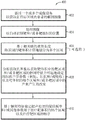
fig. 2B and 2C are flow diagrams illustrating exemplary methods for applying ultrasound waves having different frequencies to different regions of a target volume, in accordance with various embodiments;
fig. 3A illustrates adjustment of transducer settings based on real-time thermal feedback, in accordance with various embodiments;
FIG. 3B is a flow diagram illustrating an exemplary method for performing and modifying a treatment plan, in accordance with various embodiments;
fig. 4 is a flow diagram illustrating an exemplary method for optimizing one or more parameters of sonication for treating one or more target regions in a target volume, in accordance with various embodiments;
FIG. 5A illustrates the principle of electronic steering of a two-dimensional planar transducer array having a plurality of transducer elements, in accordance with various embodiments;
FIG. 5B schematically illustrates side steering of an acoustic beam by adjusting transducer settings, in accordance with various embodiments; and
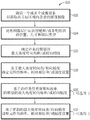
fig. 5C is a flow diagram illustrating an exemplary method for providing an acoustic beam with a desired steering angle and steering accuracy, in accordance with various embodiments.
Detailed Description
Fig. 1A is a simplified schematic diagram of an exemplary focused ultrasound system 100 for generating and delivering a focused beam of acoustic energy 102 to a target volume 104 in a patient 106. The system 100 employs an ultrasound transducer 108, the geometry and physical position of the ultrasound transducer 108 relative to the patient 106 being such as to focus the ultrasound energy beam 102 at a three-dimensional focal region located within the target volume 104. The system may shape the ultrasound energy in various ways, such as producing a point focus, a line focus, a ring focus, or multiple focuses simultaneously. The transducer 108 may be substantially rigid, semi-rigid, or substantially flexible, and may be made of a variety of materials, such as ceramics, plastics, polymers, metals, and alloys. The transducer 108 may be manufactured as a single unit or, alternatively, may be assembled from multiple components (units). Although the transducer 108 is shown as having a "spherical cap" shape, a variety of other geometries and configurations may be employed to deliver a focused acoustic beam, including other non-planar and planar (or linear) configurations. The size of the transducer may vary from millimeters to tens of centimeters depending on the application.
In various embodiments, the transducer 108 delivers a high power output with desired transmit and receive frequency response curves. For example, the transducer 108 may generate ultrasonic waves having multiple operating frequencies; systems and methods for manufacturing and configuring transducers to provide multiple frequencies and high power output are described, for example, in U.S. patent publication No. 2016/0114193, the entire disclosure of which is incorporated by reference herein. In various embodiments, the transducer 108 includes a large number of transducer elements 110 arranged in a one-, two-, or three-dimensional array or other regular manner or in a random manner. These elements 110 convert the electronic drive signals into mechanical motion and thus into acoustic waves. They may be made of, for example, a piezoceramic or a piezocomposite material, and may be mounted in silicone rubber or another material suitable for mechanical coupling between damping elements 110. The transducer elements 110 are connected via electronic drive signal paths 112 to a control device 114, the control device 114 driving the individual transducer elements 110 such that they collectively produce a focused ultrasound beam. More specifically, the control device 114 may include a beamformer 116 that sets the frequency and/or relative amplitude and phase of the drive signals in the channels 12. In a conventional focused ultrasound system containing n transducer elements, the beamformer 116 typically contains n amplifiers 118 and n phase control circuits 120, each pair driving one of the transducer elements 110. The beamformer 116 receives a Radio Frequency (RF) input signal from a frequency generator 122, typically in the range of 0.1MHz to 5 MHz. The input signal may be split into n channels for the n amplifier and phase circuits 118, 120 of the beamformer 116. Thus, in a typical system, the radio frequency generator 122 and beamformer 116 are configured to drive the individual elements 110 of the transducer 108 at the same frequency but different phases and different amplitudes so that the transducer elements 110 collectively form a phased array. In various embodiments, the amplitude and phase shifts applied by the beamformer 116 are calculated in the controller 124.
In certain embodiments, the system 100 further includes an imager 130, such as a Magnetic Resonance Imaging (MRI) device, a Computed Tomography (CT) device, a Positron Emission Tomography (PET) device, a Single Photon Emission Computed Tomography (SPECT) device, or an ultrasound scanning device, for acquiring images of target and/or non-target tissue. The acquired images may be processed by a controller 132 (or, in some embodiments, the transducer controller 124) associated with the imaging device to automatically identify the location of target and/or non-target tissue therein using suitable image processing techniques. In addition, the controller 132/124 may process the images to determine anatomical features (e.g., type, properties, structure, thickness, density, etc.) of the target/non-target tissue. The imager 130 provides a set of two-dimensional (2D) images suitable for reconstructing a three-dimensional (3D) image of the target and/or non-target tissue from which anatomical features may be inferred; alternatively, the image acquisition may be three-dimensional. In some embodiments, the controller 124/132 computationally divides the target volume 104 into multiple 3D regions based on the focal length (i.e., the distance that the ultrasound beam propagates through the tissue and the spacing material located between the transducer 108 and the patient 106 before reaching the target region); the transducer elements 110 may then direct ultrasound waves having different frequencies to different regions of the target volume, as described further below.
In some embodiments, the multi-frequency ultrasound waves are generated by multiple regions of the transducer elements. For example, referring to fig. 1B, the control device 114 may dynamically group the transducer elements 110 into a plurality of groups 132; each group 132 comprises or consists of a one-or two-dimensional array (i.e., a row or matrix) of transducer elements 110. The transducer groups 132 may be individually controllable, i.e., they may each be capable of transmitting ultrasound waves at a frequency, amplitude, and/or phase that is independent of the frequency, amplitude, and/or phase of the other groups 132. For example, referring to fig. 2A, the control device 114 may select one group 134 to collectively transmit high frequency ultrasound beams to one of the target regions 202 corresponding to short focal depths and another group 136 to collectively transmit low frequency ultrasound beams to one of the target regions 204 corresponding to long focal depths. Referring again to FIG. 1B, in one embodiment, the elements 110 in each transducer group may extend over a continuous area, and the areas covered by the different groups may or may not overlap. In another embodiment, referring to FIG. 1C, the elements 110 in each group may form a plurality of discrete regions interspersed with one another. For example, the set of transducers 134 transmitting the high frequency ultrasound beam to the target region 202 may form the discrete region 140-. It should be noted that the configuration of the transducer groups provided herein is for illustration only and the invention is not limited to such a configuration. Those of ordinary skill in the art will appreciate that many variations are possible and, therefore, are within the scope of the present invention.
Referring again to FIG. 1A, acoustic waves emitted from the transducer elements 110 form a beam 102 of acoustic energy. Typically, the transducer elements 110 are driven such that the waves converge at a focal region in the target volume 104. Within the focal region, the acoustic power of the beam 102 is (at least partially) absorbed by the tissue, thereby generating heat and raising the temperature of the tissue to a level at which cells denature and/or ablate. The degree of ultrasound absorption for the length of propagation in tissue is a function of frequency and is given by:
P t =P 0 ×(1-10 -∝fR )10 -∝f the compound of the formula (1),
wherein P is 0 Denotes the initial acoustic power of the ultrasonic beam emitted from the transducer 108, f denotes the frequency of the ultrasound (in MHz), and α denotes the absorption coefficient (in cm) in the relevant frequency range -1 ·MHz -1 In units) and can be taken from the known literature, R denotes the focal length (in cm), P t Representing the acoustic power at the target volume 104. Thus, as the depth of focus R increases, the acoustic power P in the focal region t The absorption of (b) is reduced. In some embodiments, the reduced power absorption is compensated by reducing the frequency f of the ultrasound waves, as described further below.
The goal of focused ultrasound therapy is generally to maximize the acoustic power absorbed at the target 104 while minimizing exposure to healthy tissue surrounding the target and tissue along the beam path between the transducer and the target 104. To achieve this goal, referring to fig. 2A, the target volume 104 may be divided into a plurality of regions; the transducer may then direct ultrasound waves having different frequencies to different regions of the target substantially simultaneously, sequentially, or cyclically. In one embodiment, ultrasound waves having a high frequency (e.g., 3MHz) are directed to region 202 corresponding to a relatively short focal length, while ultrasound waves having a low frequency (e.g., 1.2MHz) may be directed to region 204 corresponding to a relatively long focal length. As a result, at high frequencies, acoustic power is substantially absorbed in region 202; at low frequencies, acoustic power is substantially absorbed in region 204, while limiting power absorption in region 202. Thus, by varying the frequency of the ultrasound waves based on the focal length of the target region in the target volume 104, the acoustic power can be optimally absorbed in various regions of the target volume while avoiding overheating certain regions (which may be target or non-target regions).
Fig. 2B and 2C show exemplary methods 220, 230 according to which ultrasound waves with different frequencies are directed to different regions of the target volume 104. In a first step 222, an imaging device is activated to acquire an image of the anatomy of the patient within the target region. The image may be a 3D image or a set of 2D image slices suitable for reconstructing a 3D image of the target anatomical region. In a second step 224, the images are processed by a controller associated with the imaging device to automatically identify the location of the target and/or non-target volumes therein using suitable image processing techniques. In a third step 226, the controller may computationally divide the identified target volume into a plurality of regions based on its associated focal length. This step may involve determining the position and orientation of the target volume relative to the ultrasound transducer. In one embodiment, different imaging modalities are utilized. For example, spatial features of multiple regions in the target volume may be acquired using MRI, while the orientation and position of the transducer elements may be acquired using, for example, time-of-flight methods in ultrasound systems. As a result, it may be necessary to register the coordinate system in different imaging modalities before calculating the focal length associated with each region in the target volume. An exemplary registration method is provided, for example, in U.S. patent No. 9,934,570, the entire disclosure of which is incorporated by reference into this application.
In a fourth step 228, the transducer control apparatus 114 may group the transducer elements 110 into a plurality of groups as described above, and then determine the frequency, relative phase and/or amplitude settings of the elements in each group such that acoustic beams having a relatively higher frequency (e.g., 3MHz) are focused at a target region corresponding to a relatively shorter focal length, and acoustic beams having a relatively lower frequency (e.g., 1.2MHz) are focused at a target region corresponding to a relatively longer focal length. In addition, the control device 114 may operate one or more sets of transducer elements to generate acoustic beams having two different frequencies sequentially, cyclically, or substantially simultaneously. Alternatively, the transducers may be operated without grouping. For example, referring to fig. 2C, the control device 114 may activate at least some of the transducer elements 110 to direct an acoustic beam having a relatively high frequency (e.g., 3MHz) to a target region corresponding to a relatively short focal length (in step 238); subsequently, the control device 114 may decrease the sonication frequency and adjust the relative phases and/or amplitudes of the activated transducer elements in order to generate a new acoustic beam with a decreased frequency at the target region corresponding to the relatively longer focal length (in step 240). Steps 238 and 240 may be performed iteratively until a desired therapeutic effect is achieved at the target region.
In various embodiments, prior to treatment, a treatment plan is determined based on, for example, anatomical features (e.g., type, size, location, characteristics, structure, thickness, density, vascularization, etc.) of the target tissue and/or non-target tissue. The treatment plan may include, for example, parameters (e.g., amplitude, phase, frequency, and/or sonication duration) for generating one or more focused ultrasound waves at one or more regions in the target volume 104, one or more target temperatures corresponding to the regions in the target volume 104, and/or a maximum temperature of non-target tissue. Methods for computationally generating treatment plans based on anatomical features of target/non-target tissues are provided, for example, in U.S. patent publication No. 2015/0359603 and international application nos. PCT/IB2018/000834 (filed on day 29, 6, 2018) and PCT/IB2017/001689 (filed on day 13, 12, 2017), the entire disclosures of which are incorporated by reference into the present application.
During treatment, the ultrasound system is activated and operated according to a treatment plan. In addition, the monitoring system (e.g., MRI device 130) may measure the temperature at the target and/or non-target region in real-time and provide the measured temperature to the control device 114. The control device 114 may then update the treatment plan based on the real-time feedback and cause the ultrasound system 100 to operate according to the updated treatment plan, thereby optimizing the treatment effect on the target region and avoiding damage to non-target regions. For example, referring to fig. 3A, the high frequency waves may be first directed to begin treatment at the first target region 302. When it is detected that the temperature in the second region 304, which is located in the near-field region and may be target or non-target tissue, exceeds a predetermined threshold specified in the treatment plan, the ultrasound system 100 may switch to the low frequency mode for treatment to avoid overheating the second region 304.
Fig. 3B illustrates an exemplary method 310 for performing (and, in some embodiments, modifying) a treatment plan accordingly in various embodiments. As shown, during the treatment procedure, the controller 124 may access a memory storing the treatment plan and operate the transducer elements 110 based thereon (in step 312). For example, the transducer elements 110 may be activated according to parameter values specified in a treatment plan to transmit high frequency ultrasound waves/pulses focused at one or more target regions for treatment (e.g., thermal ablation). In a second step 314, the monitoring system may measure one or more parameter values associated with the ultrasound transducer, the target tissue, and/or the non-target tissue during the treatment. For example, the monitoring system may include an imager for measuring tissue characteristics (e.g., temperature, size, shape, or position) of target and/or non-target tissue in response to sonication. In a third step 316, based on the measured parameter values, the control device 114 may modify the treatment plan (e.g., the frequency of the applied ultrasound waves) to improve the treatment efficiency and/or avoid damage to non-target tissue. Subsequently, the operation of the transducer elements 110 may be adjusted according to the modified treatment plan (step 318). Step 314-318 may be performed iteratively throughout the treatment procedure.
Changes in the ultrasound frequency may also change the area of the focal zone at the target tissue, given by:

where a denotes the area of the focal zone for a circular transducer, λ denotes the wavelength of the ultrasound (λ ═ 2 pi/f), D denotes the diameter of the transducer element, and R denotes the focal length. Furthermore, the focal region a is inversely correlated with the peak intensity I in the focal region, satisfying:
I×A=P t formula (3)
Thus, increasing the ultrasound frequency at a given depth of focus may increase the peak sound intensity at the focal zone and then increase the temperature. Thus, selecting the ultrasound frequency at a given depth of focus reflects a trade-off between acoustic power absorption in the region of the path, power absorption at the target, and peak intensity at the region of focus. Thus, in various embodiments, the ultrasound frequencies associated with each region in the target volume 104 are optimized based on the anatomical features of the tissue therein (e.g., type, size, location, properties, structure, thickness, density, vascularization, etc.). For example, if the target region comprises highly vascular tissue having a low absorption coefficient, a high ultrasound frequency may be applied thereto to increase the peak intensity at the focal region without significantly reducing the acoustic power absorption therein. Methods for determining optimal frequency for treating a target tissue are provided, for example, in U.S. patent application 16/233,744 (filed 12/27/2018), the entire disclosure of which is incorporated herein by reference. Additionally or alternatively, other parameters of the sonication (e.g., energy level, duration of sonication, etc.) may be adjusted to optimize the therapeutic effect at the target region. For example, high power sonication may require a short duration sonication application (e.g., a short sonication time). In some embodiments, tissue acoustic parameters (e.g., tissue impedance and/or absorption) and their changes due to tissue interaction with the acoustic beam may be considered when determining the optimal frequency for treating each target region and the order in which to treat the target regions in the target volume. For example, since the acoustic absorption of coagulated tissue is relatively higher than that of non-coagulated tissue, a higher sonication frequency may be required to effectively treat a target region that includes a relatively large amount of non-coagulated tissue. Conversely, a lower sonication frequency may be sufficient to increase the temperature of the target region for treatment, which includes a relatively greater amount of coagulated tissue. Likewise, when a relatively large amount of coagulated tissue is located in the beam path region, a lower sonication frequency may be applied to avoid excessive energy absorption by non-target tissue in the beam path region. Thus, by adjusting the frequency and/or other parameters of the ultrasound waves, the present invention accommodates tissue variability in the ultrasound procedure, allowing for optimal and efficient absorption of acoustic power in various types of target regions.
Fig. 4 illustrates an exemplary method 400 for optimizing one or more parameters (e.g., frequency) of sonication to treat one or more target regions in a target volume in accordance with the present invention. In a first step 402, an imaging device is activated to acquire an image of the anatomy of a patient within a target region. In a second step 404, the images are processed by a controller associated with the imaging device to automatically identify the location of the target and/or non-target volumes therein using suitable image processing techniques. In an optional step 406, the controller may computationally divide the identified target volume into a plurality of regions based on its associated focal length. Also, this step may involve different imaging modalities, and therefore, it may be necessary (and may be implemented in a conventional manner) to register the coordinate system in different imaging modalities. In step 408, the acquired images may be analyzed to acquire anatomical features (e.g., type, size, properties, structure, thickness, density, vascularization, etc.) of tissue in each region of the target volume and/or the non-target volume. In addition, the control device 114 may analyze the acquired images to determine acoustic parameters of the tissue (e.g., impedance and/or absorption) and changes produced by the acoustic beam in each region of the target volume and/or non-target regions. In step 410, based on the anatomical features, the control device 114 may determine an optimal frequency and/or other parameters of the sonication (e.g., energy level, duration of the sonication, etc.) for treating each region of the target volume and the order of treating the target regions.
The position, shape, and intensity of the focal zone of the acoustic beam 102 is determined at least in part by the physical arrangement of the transducer elements 110, the physical positioning of the transducer 108 relative to the target volume 104, the structural and acoustic material properties of the tissue along the beam path between the transducer 108 and the target volume 104, and/or the frequency, phase shift, and/or amplitude of the drive signals. As described above, "electronic steering" of the beam 102 is achieved by setting the drive signals to focus the acoustic energy at a desired location. Fig. 5A illustrates the principle of electronic steering of a two-dimensional planar transducer array comprising a plurality of transducer elements 502. In particular, the "steer angle" of any one transducer element of the array is the angle α between the first focal axis 504 and the second focal axis 508, the first focal axis 504 extending substantially orthogonally from that element to the "un-steered" focal region 506 where the element 502 contributes the most power possible, and the second focal axis 508 extending from the transducer element 502 to the "steered to" focal region 510 located at the target volume. The "steering capability" of the transducer array is defined as the steering angle α at which the energy delivered to the steered focal zone 510 drops to half the maximum power delivered to the non-steered focal zone 506. It is apparent that the steering angle a of each transducer element of a phased array may be different, but as the distance from the element to the focal zone increases, the individual steering angles of the array elements approach the same value. In practice, because the distance between the transducer array and the target volume is sufficiently longer than the distance between the transducer elements, the steering angles associated with the transducer elements in the array may be considered to be the same. In general, the steering angle α of the beam 102 depends on the frequency of the wave. This is because the interference pattern of the acoustic beam at the target/non-target region is determined based on the shape and size of the transducer elements 110 and the wavelength of the ultrasonic waves. In general, the interference pattern includes a main lobe and side lobes with high directivity-the intensity of the lobes drops to zero at the turning angle: α ═ 1.22 × λ/D degrees (in the case of a circular transducer). Thus, high frequency ultrasound may have more accurate but limited steering capabilities (e.g., α < ± 10 °); while low frequency ultrasound waves may have greater steering capabilities (e.g., a > ± 30 °).
In various embodiments, the use of a transducer capable of generating multiple frequency waves eliminates the need for, or reduces the ability to require, a mechanical steering mechanism implemented in conventional ultrasound systems. For example, referring to fig. 5B, the control device 114 may drive the transducer elements 110 to generate an ultrasound beam 512 focused at the target volume 104 and facilitate lateral steering of the beam in a direction perpendicular to the beam propagation (e.g., along the z-axis). If a large steering angle (e.g., θ > ± 30 °) is desired (e.g., when the target spans a large volume), the control device 114 may drive the transducer elements 110 to generate a low frequency ultrasound beam. However, if more precise steering is preferred (e.g., when the tissue surrounding the target volume is a heat sensitive and/or vital organ), the control device 114 may drive the transducer elements 110 to generate an ultrasound beam having a high frequency. In general, the beams may be electronically steered in one, two, or three dimensions (e.g., along the x, z, and/or y axes). In one embodiment, the beam is steered electronically in only one dimension (e.g., along the x-axis) and a mechanical steering mechanism is used to steer the beam in the other dimension (e.g., along the y-axis). Regardless of whether the transducer 108 provides one-, two-, or three-dimensional steering (by adjusting the ultrasonic frequency), the transducer 108 is able to generate ultrasonic beams to steer various regions of the target volume 104 with a desired steering capability and accuracy.
Fig. 5C illustrates an exemplary method 520 for providing an acoustic beam with a desired steering angle and steering accuracy, in accordance with various embodiments. In a first step 522, the imaging device is activated to acquire an image of the anatomy of the patient within the target region. In a second step 524, the image is processed by a controller associated with the imaging device to automatically identify therein anatomical features (e.g., location, size, and/or tissue type) of the target and/or non-target volumes using suitable image processing techniques. In a third step 526, based on the anatomical features of the target/non-target volumes, the control device 114 may determine a desired maximum angular steering angle and/or steering accuracy of the acoustic beam. For example, a larger steering angle may be preferred when the target spans a larger volume. Furthermore, if the tissue surrounding the target volume is a thermally sensitive or vital organ, a higher steering accuracy may be required. In a fourth step 528, based on the determined maximum angular steering angle/steering accuracy, the control device 114 may determine the frequency of the element 110 (as well as other ultrasound parameters, such as relative phase and/or amplitude settings) for generating a focal region at the target volume. Additionally, the control device 114 can optionally update the desired maximum angular steering angle and/or steering accuracy of the focused beam during the ultrasound procedure based on the treatment conditions (e.g., a change in the size of the target volume or a change in the distance between the focal region in the target volume and the non-target tissue) (step 530). Subsequently, the control device 114 may adjust the frequency (and other ultrasound parameters) of the element 110 for generating a focus with an updated, desired maximum angular steering angle and/or steering accuracy (step 532).
In general, the functionality for delivering a high power acoustic output having two or more frequencies to the target volume and/or adjusting the steering angle of the acoustic beam may be configured in one or more modules implemented in hardware, software, or a combination of both, whether integrated in the controller of the ultrasound system 100 and/or the monitoring system 130, or provided by a separate external controller or other computing entity or entities. Such functions may include, for example, analyzing imaging data of the target and/or non-target volumes acquired using the imager 130, determining the location and/or anatomical features (e.g., tissue type, size, location, tissue structure, thickness, density, vascularization, etc.) of the target/non-target volumes, computationally dividing the target volume into a plurality of regions according to the associated focal length of the target volume, dividing the transducer elements into a plurality of groups, determining the frequency, relative phase and/or amplitude settings of the elements in each transducer group to produce acoustic beams having relatively higher frequencies at target regions corresponding to relatively shorter focal lengths and acoustic beams having relatively lower frequencies at target regions corresponding to relatively longer focal lengths, retrieving a treatment plan stored in memory, causing the monitoring system to measure one or more parameters associated with the ultrasound transducer during treatment, Parameter values associated with the target tissue and/or non-target tissue, modifying the treatment plan based on the measured parameter values, adjusting the operation of the transducer elements according to the modified treatment plan, determining optimal frequencies and/or other parameters for the sonication based on anatomical features of each region of the target volume, determining desired maximum angular steering angles and/or steering accuracies for the acoustic beam based on the location, size and/or tissue type of the target and/or non-target tissue, determining frequency, relative phase and/or amplitude settings for the elements based on the desired maximum angular steering angles/steering accuracies, updating the desired maximum angular steering angles and/or steering accuracies for the focused beam based on the treatment conditions, and adjusting the frequency, relative phase and/or amplitude settings for the elements based on the updated angular steering angles/steering accuracies, as described above.
The values of the ultrasound parameters (e.g., frequency, relative phase and/or amplitude) for focusing and/or steering the acoustic beam in the various target regions of the target volume 104 are determined in a control module of the controller 124, which controller 124 may be separate from the ultrasound control device 114 or may be combined with the ultrasound control device 114 into an integrated system control device. In addition, the ultrasound control device 114 and the monitoring system controller 132 may be implemented in a single, integrated control device, or form two or more separate devices that communicate therebetween. Further, the ultrasound control module and/or the control device 114 may include one or more modules implemented in hardware, software, or a combination of both. For embodiments in which functionality is provided as one or more software programs, the programs may be written in any of a number of high-level languages, such as PYTHON, FORTRAN, PASCAL, JAVA, C + +, C #, BASIC, various scripting languages, and/or HTML. Additionally, the software may be implemented in assembly language directed to a microprocessor residing on the target computer; for example, if the software is configured to run on an IBM PC or PC clone, it may be implemented In Intel 80x86 assembly language. The software may be embodied on an article of manufacture including, but not limited to, a floppy disk, a flash disk, a hard disk, an optical disk, magnetic tape, a PROM, an EPROM, an EEPROM, a field programmable gate array or a CD-ROM. Embodiments using hardware circuitry may be implemented using, for example, one or more FPGA, CPLD, or ASIC processors.
In addition, the term "controller", "control device" or "control module" as used in this application broadly includes all necessary hardware components and/or software modules for performing any of the functions described above; the controller may include multiple hardware components and/or software modules, and the functionality may be spread between different components and/or modules.
The terms and expressions which have been employed herein are used as terms of description and not of limitation, and there is no intention, in the use of such terms and expressions, of excluding any equivalents of the features shown and described or portions thereof. In addition, having described certain embodiments of the invention, it will be apparent to those of ordinary skill in the art that other embodiments incorporating the concepts disclosed herein may be used without departing from the spirit and scope of the invention. The described embodiments are, therefore, to be considered in all respects only as illustrative and not restrictive.
Claims (15)
1. A system for treating a target tissue in a target region, the system comprising:
an ultrasonic transducer for transmitting ultrasonic waves having a plurality of frequencies; and
a controller configured to:
(a) determining two or more maximum angular steering ranges of the ultrasound beam at the target area;
(b) calculating two or more frequencies of the ultrasonic waves associated with the two or more maximum angular steering ranges;
(c) causing the ultrasound transducer to generate a first ultrasound beam having a first one of the calculated frequencies; and
(d) causing the ultrasound transducer to generate a second ultrasound beam having a second one of the calculated frequencies different from the first one of the calculated frequencies to vary the maximum angular steering range of the ultrasound beam.
2. The system of claim 1, wherein the controller is further configured to steer at least one of the first or second ultrasound beams in one direction, two directions, or three directions.
3. The system of claim 1, further comprising an imaging system for acquiring anatomical features associated with the target region, the controller further configured to determine the maximum angular steering range based at least in part on the acquired anatomical features.
4. The system of claim 3, wherein the anatomical feature comprises one or more of a type, size, location, structure, density, or vascularization of the tissue.
5. The system of claim 1, wherein the ultrasound transducer comprises a plurality of transducer elements, the controller further configured to group the transducer elements into a plurality of transducer groups, each group comprising at least some of the transducer elements and being different from the other groups.
6. The system of claim 5, wherein the transducer elements of at least one of the transducer groups extend over a continuous region.
7. The system of claim 5, wherein the controller is further configured to cause a first one of the transducer groups to transmit a first ultrasound beam and a second, different one of the transducer groups to transmit a second ultrasound beam.
8. The system of claim 7, wherein the transducer elements in each of the first and second ones of the transducer groups form discrete regions.
9. The system of claim 8, wherein at least some of the discrete regions in the first and second transducer groups are interspersed.
10. The system of claim 1, wherein the transducer comprises a plurality of transducer elements, the controller further configured to cause the first and second ultrasound beams to be transmitted from different transducer elements substantially simultaneously.
11. The system of claim 1, wherein the transducer comprises a plurality of transducer elements, the controller further configured to transmit the first and second ultrasound beams cyclically from different transducer elements.
12. The system of claim 1, wherein the transducer comprises a plurality of transducer elements, the controller further configured to cause the first and second ultrasound beams to be transmitted sequentially from different transducer elements.
13. The system of claim 1, wherein the transducer comprises a plurality of transducer elements, the controller further configured to cause the first and second ultrasound beams to be transmitted from the same transducer elements substantially simultaneously.
14. The system of claim 1, wherein the transducer comprises a plurality of transducer elements, the controller further configured to cause the first and second ultrasound beams to be transmitted sequentially from the same transducer element.
15. The system of claim 1, wherein the controller is further configured to cause the ultrasound transducer to transmit the first and second ultrasound beams at an energy level above a predetermined level for target treatment.
Priority Applications (1)
| Application Number | Priority Date | Filing Date | Title |
|---|---|---|---|
| CN202210859242.0A CN115227992A (en) | 2018-01-05 | 2019-01-04 | Multi-frequency ultrasonic transducer |
Applications Claiming Priority (3)
| Application Number | Priority Date | Filing Date | Title |
|---|---|---|---|
| US201862613890P | 2018-01-05 | 2018-01-05 | |
| US62/613,890 | 2018-01-05 | ||
| PCT/IB2019/000033 WO2019135160A2 (en) | 2018-01-05 | 2019-01-04 | Multi-frequency ultrasound transducers |
Related Child Applications (1)
| Application Number | Title | Priority Date | Filing Date |
|---|---|---|---|
| CN202210859242.0A Division CN115227992A (en) | 2018-01-05 | 2019-01-04 | Multi-frequency ultrasonic transducer |
Publications (2)
| Publication Number | Publication Date |
|---|---|
| CN111757769A CN111757769A (en) | 2020-10-09 |
| CN111757769B true CN111757769B (en) | 2022-08-09 |
Family
ID=65409123
Family Applications (2)
| Application Number | Title | Priority Date | Filing Date |
|---|---|---|---|
| CN202210859242.0A Pending CN115227992A (en) | 2018-01-05 | 2019-01-04 | Multi-frequency ultrasonic transducer |
| CN201980015023.0A Active CN111757769B (en) | 2018-01-05 | 2019-01-04 | Multi-frequency ultrasonic transducer |
Family Applications Before (1)
| Application Number | Title | Priority Date | Filing Date |
|---|---|---|---|
| CN202210859242.0A Pending CN115227992A (en) | 2018-01-05 | 2019-01-04 | Multi-frequency ultrasonic transducer |
Country Status (5)
| Country | Link |
|---|---|
| US (1) | US20210077834A1 (en) |
| EP (1) | EP3735294A2 (en) |
| JP (2) | JP7321162B2 (en) |
| CN (2) | CN115227992A (en) |
| WO (1) | WO2019135160A2 (en) |
Families Citing this family (7)
| Publication number | Priority date | Publication date | Assignee | Title |
|---|---|---|---|---|
| CN113286552A (en) | 2018-11-28 | 2021-08-20 | 希斯托索尼克斯公司 | Histotripsy system and method |
| KR102335321B1 (en) * | 2019-12-10 | 2021-12-08 | 한국과학기술연구원 | Ultrasonic therapy and diagnosis apparatus implementing multiple functions using detachable circuit boards |
| CA3169465A1 (en) | 2020-01-28 | 2021-08-05 | The Regents Of The University Of Michigan | Systems and methods for histotripsy immunosensitization |
| US20210236858A1 (en) * | 2020-02-04 | 2021-08-05 | General Electric Company | Automated ultrasound bleeding detection and treatment |
| KR102445056B1 (en) * | 2020-05-08 | 2022-09-21 | (주)굿플 | Treatment aid apparatus using extracorporeal shock wave and microwave |
| CN112284493A (en) * | 2020-11-03 | 2021-01-29 | 中电科技集团重庆声光电有限公司 | Liquid level measuring method and device |
| CN116251306B (en) * | 2023-05-10 | 2023-09-01 | 深圳半岛医疗有限公司 | Control device and control method of ultrasonic therapeutic apparatus and ultrasonic therapeutic apparatus |
Citations (5)
| Publication number | Priority date | Publication date | Assignee | Title |
|---|---|---|---|---|
| EP0186732B1 (en) * | 1984-09-21 | 1993-02-03 | Rudolf Mauser | Ultrasonic determination of peripheral blood flow behaviour |
| CN2355819Y (en) * | 1999-02-12 | 1999-12-29 | 清华大学 | Ultrasonic cleaning apparatus of fixed distance cleaning for circular rotary plate |
| CN1444491A (en) * | 2000-04-21 | 2003-09-24 | 特克斯索尼克斯公司 | Systems and methods for creating longer necrosed volumes using phased array focused ultrasound system |
| CN101242872A (en) * | 2005-06-21 | 2008-08-13 | 因赛泰克有限公司 | Controlled, non-linear focused ultrasound treatment |
| CN102937692A (en) * | 2012-11-15 | 2013-02-20 | 云南电力试验研究院(集团)有限公司电力研究院 | Multi-angle ultrasound ultrahigh frequency direct current partial discharge detection device for electrical device |
Family Cites Families (18)
| Publication number | Priority date | Publication date | Assignee | Title |
|---|---|---|---|---|
| US5891041A (en) * | 1996-11-27 | 1999-04-06 | Hitachi Medical Corporation | Ultrasonic imaging system adapted for use with ultrasonic probes having different center frequencies |
| US7722539B2 (en) * | 1998-09-18 | 2010-05-25 | University Of Washington | Treatment of unwanted tissue by the selective destruction of vasculature providing nutrients to the tissue |
| JP2008509777A (en) * | 2004-08-17 | 2008-04-03 | テクニオン リサーチ アンド ディベロップメント ファウンデーション リミテッド | Treatment of tissue damage by image guidance using ultrasound |
| US7530958B2 (en) * | 2004-09-24 | 2009-05-12 | Guided Therapy Systems, Inc. | Method and system for combined ultrasound treatment |
| JP2007089992A (en) * | 2005-09-30 | 2007-04-12 | Terumo Corp | Energy irradiation device, control device and control method |
| US20100030076A1 (en) * | 2006-08-01 | 2010-02-04 | Kobi Vortman | Systems and Methods for Simultaneously Treating Multiple Target Sites |
| US20120116221A1 (en) * | 2009-04-09 | 2012-05-10 | The Trustees Of The University Of Pennsylvania | Methods and systems for image-guided treatment of blood vessels |
| US20120143100A1 (en) * | 2009-08-14 | 2012-06-07 | University Of Southern California | Extended depth-of-focus high intensity ultrasonic transducer |
| US9177543B2 (en) * | 2009-08-26 | 2015-11-03 | Insightec Ltd. | Asymmetric ultrasound phased-array transducer for dynamic beam steering to ablate tissues in MRI |
| KR101929198B1 (en) * | 2011-02-25 | 2018-12-14 | 메이오 파운데이션 포 메디칼 에쥬케이션 앤드 리써치 | Ultrasound vibrometry with unfocused ultrasound |
| US20150265856A1 (en) * | 2012-07-23 | 2015-09-24 | Lazure Scientific, Inc. | Systems, methods and devices for precision high-intensity focused ultrasound |
| EP2692287A1 (en) * | 2012-07-29 | 2014-02-05 | Ultrawave Labs Inc. | Multi-modality ultrasound and radio frequency methodology for imaging tissue |
| JP6403689B2 (en) | 2013-01-29 | 2018-10-10 | インサイテック・リミテッド | Simulation-based focused ultrasound treatment planning |
| US20160008633A1 (en) * | 2013-03-06 | 2016-01-14 | Kobi Vortman | Frequency optimization in ultrasound treatment |
| US20160114193A1 (en) | 2014-10-23 | 2016-04-28 | Oleg Prus | Multilayer ultrasound transducers for high-power transmission |
| WO2016131636A1 (en) * | 2015-02-17 | 2016-08-25 | Koninklijke Philips N.V. | Device and method for assisting in tissue ablation |
| US9934570B2 (en) | 2015-10-09 | 2018-04-03 | Insightec, Ltd. | Systems and methods for registering images obtained using various imaging modalities and verifying image registration |
| US20170281982A1 (en) * | 2016-03-31 | 2017-10-05 | Family Health International | Methods and systems for generating an occlusion using ultrasound |
-
2019
- 2019-01-04 WO PCT/IB2019/000033 patent/WO2019135160A2/en unknown
- 2019-01-04 EP EP19704861.4A patent/EP3735294A2/en active Pending
- 2019-01-04 CN CN202210859242.0A patent/CN115227992A/en active Pending
- 2019-01-04 JP JP2020537171A patent/JP7321162B2/en active Active
- 2019-01-04 US US16/959,914 patent/US20210077834A1/en active Pending
- 2019-01-04 CN CN201980015023.0A patent/CN111757769B/en active Active
-
2023
- 2023-07-25 JP JP2023120835A patent/JP2023134811A/en active Pending
Patent Citations (5)
| Publication number | Priority date | Publication date | Assignee | Title |
|---|---|---|---|---|
| EP0186732B1 (en) * | 1984-09-21 | 1993-02-03 | Rudolf Mauser | Ultrasonic determination of peripheral blood flow behaviour |
| CN2355819Y (en) * | 1999-02-12 | 1999-12-29 | 清华大学 | Ultrasonic cleaning apparatus of fixed distance cleaning for circular rotary plate |
| CN1444491A (en) * | 2000-04-21 | 2003-09-24 | 特克斯索尼克斯公司 | Systems and methods for creating longer necrosed volumes using phased array focused ultrasound system |
| CN101242872A (en) * | 2005-06-21 | 2008-08-13 | 因赛泰克有限公司 | Controlled, non-linear focused ultrasound treatment |
| CN102937692A (en) * | 2012-11-15 | 2013-02-20 | 云南电力试验研究院(集团)有限公司电力研究院 | Multi-angle ultrasound ultrahigh frequency direct current partial discharge detection device for electrical device |
Also Published As
| Publication number | Publication date |
|---|---|
| US20210077834A1 (en) | 2021-03-18 |
| CN115227992A (en) | 2022-10-25 |
| CN111757769A (en) | 2020-10-09 |
| JP2021510104A (en) | 2021-04-15 |
| WO2019135160A3 (en) | 2019-09-06 |
| WO2019135160A2 (en) | 2019-07-11 |
| JP7321162B2 (en) | 2023-08-04 |
| EP3735294A2 (en) | 2020-11-11 |
| JP2023134811A (en) | 2023-09-27 |
Similar Documents
| Publication | Publication Date | Title |
|---|---|---|
| CN111757769B (en) | Multi-frequency ultrasonic transducer | |
| US11207547B2 (en) | Probe for ultrasound tissue treatment | |
| CN109475755B (en) | Ultrasonic autofocus using reflection | |
| JP7119089B2 (en) | Focusing ultrasound in dynamically changing media | |
| JP6749108B2 (en) | Method and system for controlled heat treatment of human surface texture | |
| US7530356B2 (en) | Method and system for noninvasive mastopexy | |
| JP4558504B2 (en) | Correction of tissue abnormalities in ultrasonic therapy | |
| US9177543B2 (en) | Asymmetric ultrasound phased-array transducer for dynamic beam steering to ablate tissues in MRI | |
| CA2860065C (en) | Method and system for combined ultrasound treatment | |
| US6135971A (en) | Apparatus for deposition of ultrasound energy in body tissue | |
| JP2020501826A (en) | System and method for performing transcranial ultrasound therapy and imaging procedures | |
| US20100030076A1 (en) | Systems and Methods for Simultaneously Treating Multiple Target Sites | |
| CN109689160B (en) | Therapeutic ultrasound with reduced interference from microbubbles | |
| JP7302936B2 (en) | Optimization of transducer configuration in ultrasound procedures | |
| US20230145064A1 (en) | Variable-bandwidth transducers with asymmetric features |
Legal Events
| Date | Code | Title | Description |
|---|---|---|---|
| PB01 | Publication | ||
| PB01 | Publication | ||
| SE01 | Entry into force of request for substantive examination | ||
| SE01 | Entry into force of request for substantive examination | ||
| GR01 | Patent grant | ||
| GR01 | Patent grant |