CN111692086A - Water yield automatic detection water pump - Google Patents
Water yield automatic detection water pump Download PDFInfo
- Publication number
- CN111692086A CN111692086A CN202010605655.7A CN202010605655A CN111692086A CN 111692086 A CN111692086 A CN 111692086A CN 202010605655 A CN202010605655 A CN 202010605655A CN 111692086 A CN111692086 A CN 111692086A
- Authority
- CN
- China
- Prior art keywords
- wall
- cavity
- fixedly arranged
- water
- block
- Prior art date
- Legal status (The legal status is an assumption and is not a legal conclusion. Google has not performed a legal analysis and makes no representation as to the accuracy of the status listed.)
- Withdrawn
Links
- XLYOFNOQVPJJNP-UHFFFAOYSA-N water Substances O XLYOFNOQVPJJNP-UHFFFAOYSA-N 0.000 title claims abstract description 90
- 238000001514 detection method Methods 0.000 title claims description 7
- 230000005540 biological transmission Effects 0.000 claims description 30
- 239000002184 metal Substances 0.000 claims description 10
- 238000004804 winding Methods 0.000 claims description 9
- 230000005484 gravity Effects 0.000 claims description 3
- 230000008878 coupling Effects 0.000 claims description 2
- 238000010168 coupling process Methods 0.000 claims description 2
- 238000005859 coupling reaction Methods 0.000 claims description 2
- 238000007689 inspection Methods 0.000 claims 1
- 239000002699 waste material Substances 0.000 abstract description 4
- 239000007788 liquid Substances 0.000 description 4
- 238000001914 filtration Methods 0.000 description 3
- 230000009286 beneficial effect Effects 0.000 description 1
- 238000010586 diagram Methods 0.000 description 1
- 238000012986 modification Methods 0.000 description 1
- 230000004048 modification Effects 0.000 description 1
- 230000000149 penetrating effect Effects 0.000 description 1
Images


Classifications
-
- F—MECHANICAL ENGINEERING; LIGHTING; HEATING; WEAPONS; BLASTING
- F04—POSITIVE - DISPLACEMENT MACHINES FOR LIQUIDS; PUMPS FOR LIQUIDS OR ELASTIC FLUIDS
- F04B—POSITIVE-DISPLACEMENT MACHINES FOR LIQUIDS; PUMPS
- F04B49/00—Control, e.g. of pump delivery, or pump pressure of, or safety measures for, machines, pumps, or pumping installations, not otherwise provided for, or of interest apart from, groups F04B1/00 - F04B47/00
- F04B49/02—Stopping, starting, unloading or idling control
- F04B49/025—Stopping, starting, unloading or idling control by means of floats
-
- B—PERFORMING OPERATIONS; TRANSPORTING
- B01—PHYSICAL OR CHEMICAL PROCESSES OR APPARATUS IN GENERAL
- B01D—SEPARATION
- B01D29/00—Filters with filtering elements stationary during filtration, e.g. pressure or suction filters, not covered by groups B01D24/00 - B01D27/00; Filtering elements therefor
- B01D29/01—Filters with filtering elements stationary during filtration, e.g. pressure or suction filters, not covered by groups B01D24/00 - B01D27/00; Filtering elements therefor with flat filtering elements
- B01D29/03—Filters with filtering elements stationary during filtration, e.g. pressure or suction filters, not covered by groups B01D24/00 - B01D27/00; Filtering elements therefor with flat filtering elements self-supporting
-
- B—PERFORMING OPERATIONS; TRANSPORTING
- B01—PHYSICAL OR CHEMICAL PROCESSES OR APPARATUS IN GENERAL
- B01D—SEPARATION
- B01D29/00—Filters with filtering elements stationary during filtration, e.g. pressure or suction filters, not covered by groups B01D24/00 - B01D27/00; Filtering elements therefor
- B01D29/50—Filters with filtering elements stationary during filtration, e.g. pressure or suction filters, not covered by groups B01D24/00 - B01D27/00; Filtering elements therefor with multiple filtering elements, characterised by their mutual disposition
- B01D29/56—Filters with filtering elements stationary during filtration, e.g. pressure or suction filters, not covered by groups B01D24/00 - B01D27/00; Filtering elements therefor with multiple filtering elements, characterised by their mutual disposition in series connection
-
- B—PERFORMING OPERATIONS; TRANSPORTING
- B01—PHYSICAL OR CHEMICAL PROCESSES OR APPARATUS IN GENERAL
- B01D—SEPARATION
- B01D29/00—Filters with filtering elements stationary during filtration, e.g. pressure or suction filters, not covered by groups B01D24/00 - B01D27/00; Filtering elements therefor
- B01D29/62—Regenerating the filter material in the filter
-
- B—PERFORMING OPERATIONS; TRANSPORTING
- B01—PHYSICAL OR CHEMICAL PROCESSES OR APPARATUS IN GENERAL
- B01D—SEPARATION
- B01D29/00—Filters with filtering elements stationary during filtration, e.g. pressure or suction filters, not covered by groups B01D24/00 - B01D27/00; Filtering elements therefor
- B01D29/96—Filters with filtering elements stationary during filtration, e.g. pressure or suction filters, not covered by groups B01D24/00 - B01D27/00; Filtering elements therefor in which the filtering elements are moved between filtering operations; Particular measures for removing or replacing the filtering elements; Transport systems for filters
-
- F—MECHANICAL ENGINEERING; LIGHTING; HEATING; WEAPONS; BLASTING
- F04—POSITIVE - DISPLACEMENT MACHINES FOR LIQUIDS; PUMPS FOR LIQUIDS OR ELASTIC FLUIDS
- F04B—POSITIVE-DISPLACEMENT MACHINES FOR LIQUIDS; PUMPS
- F04B53/00—Component parts, details or accessories not provided for in, or of interest apart from, groups F04B1/00 - F04B23/00 or F04B39/00 - F04B47/00
- F04B53/20—Filtering
Abstract
The invention discloses a water pump capable of automatically detecting water quantity, which comprises a machine shell, wherein a lifting mechanism is arranged in the machine shell, the lifting mechanism comprises a water inlet pipe arranged in the shell, a water suction pump is fixedly arranged in the water inlet pipe, a water outlet pipe is arranged on the inner wall of the right side of the water inlet pipe, a moving cavity is arranged in the machine shell, a pushing mechanism is arranged in the moving cavity, the pushing mechanism comprises a power supply fixed on the inner wall of the upper side of the moving cavity, the inner wall of the left side of the water inlet pipe is provided with a transverse cavity, the rotating mechanism is arranged in the transverse cavity and comprises a vertical shaft which is rotatably arranged on the inner wall of the upper side of the transverse cavity, a rotating disc is fixedly arranged on the vertical shaft, the device can monitor water in real time, can be automatic close the water pump when not having water, avoid the water pump idle running, cause the waste, and this device can also carry out automatic mediation to the water pump of jam, greatly reduced artifical loss.
Description
Technical Field
The invention relates to the field of water pumps, in particular to a water pump capable of automatically detecting water quantity.
Background
The water pump is the machinery that carries liquid or make liquid pressure boost, and it conveys the mechanical energy of prime mover or other external energy to liquid, makes the liquid energy increase, and general water pump needs someone to look after by the side when carrying water, in time stops the water pump after the water is taken out futilely, avoids causing the waste, and general water pump need manual work to clear up after blockking up, very waste time.
Disclosure of Invention
The invention aims to solve the technical problem of providing a water pump capable of automatically detecting the water quantity, and solves the problems that a common water pump needs to be manually cleaned, needs to be manually closed after water is not available and the like.
The invention is realized by the following technical scheme.
The invention discloses an automatic water quantity detection water pump which comprises a machine shell, wherein a lifting mechanism is arranged in the machine shell, the lifting mechanism comprises a water inlet pipe arranged in the machine shell, a water suction pump is fixedly arranged in the water inlet pipe, a water outlet pipe is arranged on the inner wall of the right side of the water inlet pipe, sliding grooves are formed in the inner wall of the left side and the inner wall of the rear side of the water inlet pipe, sliding blocks are arranged in the sliding grooves in a vertically moving mode, a filter block is fixedly arranged between the two sliding blocks, three filter pipes are arranged in the filter block in a vertically penetrating mode, and the upper end; a moving cavity is arranged in the shell, a pushing mechanism is arranged in the moving cavity and comprises a power supply fixed on the inner wall of the upper side of the moving cavity, an insulating groove is formed in the inner wall of the upper side of the moving cavity, a metal block is fixedly arranged on the inner wall of the upper side of the insulating groove, a connecting block is arranged in the insulating groove in a manner of moving left and right, and an insulating spring is connected between the right end face of the connecting block and the inner wall of the right side of the insulating groove; the water inlet pipe is characterized in that a transverse cavity is formed in the inner wall of the left side of the water inlet pipe, a rotating mechanism is arranged in the transverse cavity and comprises a vertical shaft rotatably arranged on the inner wall of the upper side of the transverse cavity, a rotating disc is fixedly arranged on the vertical shaft, three hollow pipes are arranged in the rotating disc in a vertically movable manner, communicating pipes are arranged in the hollow pipes in a vertically communicated manner, limiting blocks are fixedly arranged on the hollow pipes, connecting rods are fixedly arranged between the hollow pipes, a transmission motor is fixedly arranged on the inner wall of the rear side of the motor cavity, a motor shaft is rotatably arranged on the front end face of the transmission motor, a motor half gear is fixedly arranged on the motor shaft, two limiting grooves are arranged on the inner wall of the rear side of the motor cavity, limiting blocks are arranged in the limiting grooves in a vertically movable manner, a fixing rod is fixedly arranged on, the movable frame is characterized in that a connecting plate is fixedly arranged on the front end face of the movable frame, and the hollow tube is fixedly arranged on the front end face of the connecting plate.
Preferably, the left side be equipped with the contact chamber in the sliding tray upside inner wall, the left side sliding tray upside inner wall is equipped with the decurrent lift groove of opening, the lift inslot can reciprocate and be equipped with the transfer line, the fixed vertical rack that is equipped with of transfer line left end face, the transfer line up end with be connected with coupling spring between the side inner wall of lift inslot, contact chamber rear side inner wall rotates and is equipped with the driven shaft, from last fixed driving pulley and the contact gear that is equipped with in proper order backward of following of driven shaft, the last belt that winds of driving pulley.
Preferably, the fixed pipe that is equipped with of terminal surface under the casing, it is equipped with fixed pipe to link up from top to bottom in the fixed pipe, it is equipped with the water inlet to link up from top to bottom in the fixed pipe, the internal fixed filter screen that is equipped with of water inlet, fixed pipe lower extreme terminal surface is equipped with the unsteady chamber of opening downwards, the intracavity that floats can reciprocate and be equipped with the kicking block, be equipped with perpendicular groove in the unsteady intracavity upside inner wall, it is equipped with the movable block to erect the inslot, the kicking block up end with be connected with the linking arm under the movable block between the terminal surface, the fixed transmission arm.
Preferably, a rope winding cavity is arranged in the casing, a rope winding wheel is fixedly arranged on the vertical shaft, the pull rope is wound on the rope winding wheel, a reset torsion spring is arranged between the vertical shaft and the inner wall of the upper side of the horizontal cavity, a vertical cavity is arranged in the inner wall of the lower side of the horizontal cavity, a pushing cavity is arranged in the inner wall of the lower side of the vertical cavity, a metal rotating block is fixedly arranged on the lower end face of the vertical shaft, a loading plate can be vertically moved in the vertical cavity, a plug is fixedly arranged on the upper end face of the loading plate, a connecting shaft is rotatably arranged on the inner wall of the right side of the pushing cavity, a pushing rod is fixedly arranged on the connecting shaft, a transmission cavity is arranged in the casing, a transmission shaft is rotatably arranged on the inner wall of the rear side of the transmission cavity, a driven pulley and a transmission bevel gear are fixedly arranged on the transmission, The power supply is electrically connected with the water pump.
Preferably, the elastic force of the reset torsion spring is smaller than the gravity of the sliding block, and the elastic force of the connecting spring is smaller than the elastic force of the reset torsion spring.
The invention has the beneficial effects that: this device can carry out real-time supervision to water, can close the water pump automatically when not having water, avoids the water pump idle running, causes the waste, and this device can also carry out automatic mediation to the water pump of jam, greatly reduced artifical loss.
Drawings
In order to more clearly illustrate the embodiments of the invention or the technical solutions in the prior art, the drawings used in the description of the embodiments or the prior art will be briefly described below, and it is obvious that the drawings in the following description are only some embodiments of the invention, and it is obvious for those skilled in the art that other drawings can be obtained based on these drawings without creative efforts.
FIG. 1 is a schematic structural diagram of an embodiment of the present invention;
FIG. 2 is an enlarged view of the point A in FIG. 1;
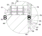
FIG. 3 is a schematic view of the direction B-B in FIG. 2;
fig. 4 is a schematic view in the direction of C-C in fig. 1.
Detailed Description
The invention will now be described in detail with reference to fig. 1-4, wherein for ease of description the orientations described hereinafter are now defined as follows: the up, down, left, right, and front-back directions described below correspond to the up, down, left, right, and front-back directions in the projection relationship of fig. 1 itself.
The water pump for automatically detecting the water amount is described with reference to fig. 1-4, and includes a casing 22, a lifting mechanism 80 is provided in the casing 22, the lifting mechanism 80 includes a water inlet pipe 28 provided in the casing 22, a water pump 26 is fixedly provided in the water inlet pipe 28, a water outlet pipe 27 is provided on the inner wall of the right side of the water inlet pipe 28, sliding grooves 30 are provided on the inner wall of the left side and the inner wall of the rear side of the water inlet pipe 28, sliding blocks 31 are provided in the sliding grooves 30 to be capable of moving up and down, a filter block 33 is fixedly provided between the two sliding blocks 31, three filter pipes 32 are provided in the filter block 33 to run through from top to bottom, and; a moving cavity 39 is arranged in the machine shell 22, a pushing mechanism 81 is arranged in the moving cavity 39, the pushing mechanism 81 comprises a power supply 36 fixed on the inner wall of the upper side of the moving cavity 39, an insulating groove 37 is arranged in the inner wall of the upper side of the moving cavity 39, a metal block 34 is fixedly arranged on the inner wall of the upper side of the insulating groove 37, a connecting block 38 is arranged in the insulating groove 37 in a manner of moving left and right, and an insulating spring 35 is connected between the right end surface of the connecting block 38 and the inner wall of the right side of the insulating; the inner wall of the left side of the water inlet pipe 28 is provided with a transverse cavity 77, a rotating mechanism 82 is arranged in the transverse cavity 77, the rotating mechanism 82 comprises a vertical shaft 78 which is rotatably arranged on the inner wall of the upper side of the transverse cavity 77, a rotating disc 51 is fixedly arranged on the vertical shaft 78, three hollow pipes 52 can be vertically moved in the rotating disc 51, a communicating pipe 53 is vertically communicated and arranged in each hollow pipe 52, a limiting block 49 is fixedly arranged on each hollow pipe 52, a connecting rod 50 is fixedly arranged between the hollow pipes 52, a transmission motor 64 is fixedly arranged on the inner wall of the rear side of the motor cavity 54, a motor shaft 66 is rotatably arranged on the front end face of the transmission motor 64, a motor half gear 67 is fixedly arranged on the motor shaft 66, two limiting grooves 63 are arranged on the inner wall of the rear side of the motor cavity 54, limiting blocks 62 can be vertically moved in the limiting grooves, the fixed frame 68 that removes that is equipped with of terminal surface before the dead lever 65, the terminal surface is equipped with the connection chamber 61 behind the frame 68 of removing, the terminal surface is fixed and is equipped with connecting plate 69 before the frame 68 of removing, the terminal surface is fixed and is equipped with before connecting plate 69 hollow tube 52.
Beneficially, the left side be equipped with in the 30 upside inner walls of sliding tray and contact chamber 21, the left side 30 upside inner walls of sliding tray are equipped with the decurrent lift groove 24 of opening, can reciprocate in the lift groove 24 and be equipped with transfer line 29, the fixed vertical rack 23 that is equipped with of transfer line 29 left end face, transfer line 29 up end with be connected with connecting spring 25 between the 24 upside inner walls of lift groove, contact chamber 21 rear side inner wall rotates and is equipped with driven shaft 19, it is equipped with driving pulley 70 and contact gear 20 to follow last fixed being equipped with in proper order backward on the driven shaft 19, around there being belt 18 on the driving pulley 70.
Beneficially, fixed pipe 48 is fixedly arranged on the lower end face of the machine shell 22, fixed pipe 48 is arranged in the fixed pipe 48 in a vertically through mode, a water inlet 47 is arranged in the fixed pipe 48 in a vertically through mode, a filter screen 46 is arranged in the water inlet 47 in a fixed mode, a floating cavity 44 with a downward opening is arranged on the lower end face of the fixed pipe 48, a floating block 45 is arranged in the floating cavity 44 in a vertically moving mode, a vertical groove 41 is formed in the inner wall of the upper side of the floating cavity 44, a moving block 42 is arranged in the vertical groove 41 in a vertically moving mode, a connecting arm 43 is connected between the upper end face of the floating block 45 and the lower end face of the moving block 42, and a transmission arm 40.
Beneficially, be equipped with rope winding chamber 17 in the casing 22, fixed being equipped with rope winding wheel 16 on the vertical axis 78, the last rope winding wheel 16 of having twined stay 13, vertical axis 78 with be equipped with reset torsion spring 14 between the lateral cavity 77 upside inner wall, be equipped with perpendicular chamber 55 in the lateral cavity 77 downside inner wall, be equipped with in the perpendicular chamber 55 downside inner wall and promote chamber 60, the terminal surface is fixed to be equipped with metal turning block 79 under the vertical axis 78, can reciprocate in perpendicular chamber 55 and be equipped with year thing board 57, the terminal surface is fixed and is equipped with plug 56 on the year thing board 57, it is equipped with connecting axle 58 to promote the rotation of chamber 60 right side inner wall, be equipped with catch bar 59 on the connecting axle 58 fixed be equipped with transmission chamber 12 in the casing 22, the rotation of transmission chamber 12 rear side inner wall is equipped with transmission shaft 11, it is fixed with driven pulley 71 and drive bevel gear 10 in proper order from the back to the front on the transmission shaft 11, driven, a driven bevel gear 75 is fixedly arranged on the connecting shaft 58, and the metal block 34 and the power supply 36 are electrically connected with the water pump 26.
Advantageously, the elastic force of the return torsion spring 14 is smaller than the gravity of the sliding block 31, and the elastic force of the connecting spring 25 is smaller than the elastic force of the return torsion spring 14.
In the initial state, the return torsion spring 14 is in a compressed state, and the connecting spring 25 and the insulating spring 35 are in a normal state.
When the water purifier works, the machine shell 22 is placed into water, the floating block 45 moves upwards under the buoyancy of the water, the floating block 45 drives the connecting arm 43 to move upwards, the connecting arm 43 drives the moving block 42 to move upwards, the moving block 42 drives the driving arm 40 to move upwards, the driving arm 40 moves upwards, the connecting block 38 is pushed to move rightwards, the fixed pipe 48 moves rightwards, the metal block 34 is communicated with the power supply 36, the water pump 26 is started, the water pump 26 sucks water through the water inlet 47 and discharges the water from the water outlet pipe 27, when the filtering pipe 32 is blocked, the water pump 26 can enable the filtering block 33 to move upwards, the filtering block 33 drives the sliding block 31 to move upwards, the sliding block 31 moves upwards, the pull rope 13 is loosened, the reset torsion spring 14 drives the vertical shaft 15 to rotate, the vertical shaft 15 drives the rotating disc 51 to rotate, the sliding block 31 moves upwards to push the, the contact gear 20 drives the transmission belt wheel 70 to rotate through the driven shaft 19, the transmission belt wheel 70 drives the driven belt wheel 71 to rotate through the friction of the belt 18, the driven belt wheel 71 drives the transmission shaft 11 to rotate, the transmission shaft 11 drives the transmission bevel gear 10 to rotate, the transmission bevel gear 10 is meshed to drive the driven bevel gear 75 to rotate, the driven bevel gear 75 drives the push rod 59 to rotate through the connecting shaft 58, the push rod 59 pushes the carrying plate 57 to move upwards, the carrying plate 57 drives the plug 56 to move upwards, the plug 56 is in contact with the metal rotating block 79, the transmission motor 64 is started, the transmission motor 64 drives the motor shaft 66 to rotate, the motor shaft 66 drives the motor half gear 67 to rotate, the motor half gear 67 drives the moving frame 68 to move upwards and downwards, the moving frame 68 drives the hollow pipe 52 to move upwards and downwards through the connecting plate.
The above embodiments are merely illustrative of the technical ideas and features of the present invention, and the purpose thereof is to enable those skilled in the art to understand the contents of the present invention and implement the present invention, and not to limit the protection scope of the present invention. All equivalent changes and modifications made according to the spirit of the present invention should be covered within the protection scope of the present invention.
Claims (5)
1. The utility model provides a water yield automated inspection water pump, includes the casing, its characterized in that: the water pump is fixedly arranged in the water inlet pipe, the inner wall of the right side of the water inlet pipe is provided with a water outlet pipe, the inner wall of the left side and the inner wall of the rear side of the water inlet pipe are provided with sliding grooves, sliding blocks can move up and down in the sliding grooves, a filter block is fixedly arranged between the two sliding blocks, three filter pipes are vertically arranged in the filter block in a through manner, and the upper end face of each sliding block is connected with a pull rope; a moving cavity is arranged in the shell, a pushing mechanism is arranged in the moving cavity and comprises a power supply fixed on the inner wall of the upper side of the moving cavity, an insulating groove is formed in the inner wall of the upper side of the moving cavity, a metal block is fixedly arranged on the inner wall of the upper side of the insulating groove, a connecting block is arranged in the insulating groove in a manner of moving left and right, and an insulating spring is connected between the right end face of the connecting block and the inner wall of the right side of the insulating groove; the water inlet pipe is characterized in that a transverse cavity is formed in the inner wall of the left side of the water inlet pipe, a rotating mechanism is arranged in the transverse cavity and comprises a vertical shaft rotatably arranged on the inner wall of the upper side of the transverse cavity, a rotating disc is fixedly arranged on the vertical shaft, three hollow pipes are arranged in the rotating disc in a vertically movable manner, communicating pipes are arranged in the hollow pipes in a vertically communicated manner, limiting blocks are fixedly arranged on the hollow pipes, connecting rods are fixedly arranged between the hollow pipes, a transmission motor is fixedly arranged on the inner wall of the rear side of the motor cavity, a motor shaft is rotatably arranged on the front end face of the transmission motor, a motor half gear is fixedly arranged on the motor shaft, two limiting grooves are arranged on the inner wall of the rear side of the motor cavity, limiting blocks are arranged in the limiting grooves in a vertically movable manner, a fixing rod is fixedly arranged on, the movable frame is characterized in that a connecting plate is fixedly arranged on the front end face of the movable frame, and the hollow tube is fixedly arranged on the front end face of the connecting plate.
2. The automatic water quantity detection water pump according to claim 1, characterized in that: left side be equipped with in the sliding tray upside inner wall and touch the chamber, the left side sliding tray upside inner wall is equipped with the decurrent lift groove of opening, the lift inslot can reciprocate and be equipped with the transfer line, the fixed perpendicular rack that is equipped with of transfer line left end face, the transfer line up end with be connected with coupling spring between the inner wall of lifting tray upside, touch chamber rear side inner wall and rotate and be equipped with the driven shaft, follow the fixed driving pulley and the contact gear that are equipped with forward in proper order after on the driven shaft, around there being the belt on the driving pulley.
3. The automatic water quantity detection water pump according to claim 1, characterized in that: the fixed pipe that is equipped with of terminal surface under the casing, it is equipped with fixed pipe to link up from top to bottom in the fixed pipe, it is equipped with the water inlet to link up from top to bottom in the fixed pipe, the internal fixed filter screen that is equipped with of water inlet, the terminal surface is equipped with the unsteady chamber of opening decurrent under the fixed pipe, the intracavity that floats can reciprocate and be equipped with the kicking block, be equipped with in the unsteady intracavity upside inner wall and erect the groove, it is equipped with the movable block to erect the inslot, the kicking block up end with be connected with the linking arm under the movable block between the terminal.
4. The automatic water quantity detection water pump according to claim 3, characterized in that: a rope winding cavity is arranged in the machine shell, a rope winding wheel is fixedly arranged on the vertical shaft, the pull rope is wound on the rope winding wheel, a reset torsion spring is arranged between the vertical shaft and the inner wall of the upper side of the transverse cavity, a vertical cavity is arranged in the inner wall of the lower side of the transverse cavity, a pushing cavity is arranged in the inner wall of the lower side of the vertical cavity, a metal rotating block is fixedly arranged on the lower end face of the vertical shaft, a loading plate is arranged in the vertical cavity and can move up and down, a plug is fixedly arranged on the upper end surface of the loading plate, a connecting shaft is rotatably arranged on the inner wall of the right side of the pushing cavity, a pushing rod is fixedly arranged on the connecting shaft, a transmission cavity is arranged in the shell, a transmission shaft is rotatably arranged on the inner wall of the rear side of the transmission cavity, a driven belt wheel and a transmission bevel gear are fixedly arranged on the transmission shaft from back to front in sequence, the belt is wound on the driven belt wheel, a driven bevel gear is fixedly arranged on the connecting shaft, and the metal block and the power supply are electrically connected with the water suction pump.
5. The automatic water quantity detection water pump according to claim 4, characterized in that: the elastic force of the reset torsion spring is smaller than the gravity of the sliding block, and the elastic force of the connecting spring is smaller than the elastic force of the reset torsion spring.
Priority Applications (1)
| Application Number | Priority Date | Filing Date | Title |
|---|---|---|---|
| CN202010605655.7A CN111692086A (en) | 2020-06-29 | 2020-06-29 | Water yield automatic detection water pump |
Applications Claiming Priority (1)
| Application Number | Priority Date | Filing Date | Title |
|---|---|---|---|
| CN202010605655.7A CN111692086A (en) | 2020-06-29 | 2020-06-29 | Water yield automatic detection water pump |
Publications (1)
| Publication Number | Publication Date |
|---|---|
| CN111692086A true CN111692086A (en) | 2020-09-22 |
Family
ID=72484414
Family Applications (1)
| Application Number | Title | Priority Date | Filing Date |
|---|---|---|---|
| CN202010605655.7A Withdrawn CN111692086A (en) | 2020-06-29 | 2020-06-29 | Water yield automatic detection water pump |
Country Status (1)
| Country | Link |
|---|---|
| CN (1) | CN111692086A (en) |
Cited By (2)
| Publication number | Priority date | Publication date | Assignee | Title |
|---|---|---|---|---|
| CN112594403A (en) * | 2021-01-26 | 2021-04-02 | 深圳市俏夕阳贸易有限公司 | Intelligent water-saving faucet with water pressure detection function and automatic water closing function |
| CN114046258A (en) * | 2021-10-14 | 2022-02-15 | 扬州市瑞峰泵业制造有限公司 | Water pump with water level induction prevents overheated |
-
2020
- 2020-06-29 CN CN202010605655.7A patent/CN111692086A/en not_active Withdrawn
Cited By (3)
| Publication number | Priority date | Publication date | Assignee | Title |
|---|---|---|---|---|
| CN112594403A (en) * | 2021-01-26 | 2021-04-02 | 深圳市俏夕阳贸易有限公司 | Intelligent water-saving faucet with water pressure detection function and automatic water closing function |
| CN114046258A (en) * | 2021-10-14 | 2022-02-15 | 扬州市瑞峰泵业制造有限公司 | Water pump with water level induction prevents overheated |
| CN114046258B (en) * | 2021-10-14 | 2024-01-23 | 扬州市瑞峰泵业制造有限公司 | Water pump with water level induction for preventing overheating |
Similar Documents
| Publication | Publication Date | Title |
|---|---|---|
| CN111692086A (en) | Water yield automatic detection water pump | |
| CN111397203B (en) | Water heater with incrustation scale removing function | |
| CN107366640A (en) | A kind of vapour-pressure type pumping method and suction pump | |
| CN111701957A (en) | Device for cleaning inner wall of sewage drain pipe | |
| CN111271296B (en) | Self-blockage-cleaning type submersible pump | |
| CN111929106A (en) | Medical urine collecting device | |
| CN112012967A (en) | Filtration formula water pump damping device | |
| CN217163439U (en) | Sewage treatment device | |
| CN112499706A (en) | River irrigation device capable of automatically withdrawing water pumping pipe and removing impurities | |
| CN115095528A (en) | Environment-friendly energy-saving sewage pump | |
| CN111481978A (en) | For kitchen use sewage filtration equipment | |
| CN217275175U (en) | Automatic water trap of positive pole unbaked block | |
| CN112717526A (en) | Energy-saving equipment for cleaning outside of water pump | |
| CN111981896A (en) | Pressure-adjustable heat exchanger heat transfer pipe cleaning device | |
| CN111715573A (en) | Water pump cover maintenance device | |
| CN215483252U (en) | Water diversion device for water conservancy and hydropower engineering | |
| CN110624896A (en) | Rotatory belt cleaning device of ultrasonic wave suitable for irregular article | |
| CN220642688U (en) | High-efficient profit layering cauldron | |
| CN111305354A (en) | Self-dredging valve for sewage pipeline | |
| CN117738939B (en) | Single-stage end suction centrifugal pump capable of reducing efficiency loss | |
| CN220890485U (en) | Chemical pump for chemical production | |
| CN216339872U (en) | Building water supply and drainage device with self-dredging function | |
| CN211648476U (en) | Sewage pump that domestic sewage used | |
| CN217442019U (en) | Full-automatic transparent ice maker | |
| CN216337042U (en) | Spraying room water treatment facilities |
Legal Events
| Date | Code | Title | Description |
|---|---|---|---|
| PB01 | Publication | ||
| PB01 | Publication | ||
| SE01 | Entry into force of request for substantive examination | ||
| SE01 | Entry into force of request for substantive examination | ||
| WW01 | Invention patent application withdrawn after publication | ||
| WW01 | Invention patent application withdrawn after publication |
Application publication date: 20200922 |