CN111683828A - Symmetrical dynamic equalization of volumetric and pressure air management systems - Google Patents
Symmetrical dynamic equalization of volumetric and pressure air management systems Download PDFInfo
- Publication number
- CN111683828A CN111683828A CN201880074134.4A CN201880074134A CN111683828A CN 111683828 A CN111683828 A CN 111683828A CN 201880074134 A CN201880074134 A CN 201880074134A CN 111683828 A CN111683828 A CN 111683828A
- Authority
- CN
- China
- Prior art keywords
- air
- vehicle
- valve
- system controller
- pneumatic circuit
- Prior art date
- Legal status (The legal status is an assumption and is not a legal conclusion. Google has not performed a legal analysis and makes no representation as to the accuracy of the status listed.)
- Pending
Links
- 238000004891 communication Methods 0.000 claims abstract description 169
- 230000007935 neutral effect Effects 0.000 claims description 100
- 238000012545 processing Methods 0.000 claims description 64
- 238000000034 method Methods 0.000 claims description 41
- 238000005259 measurement Methods 0.000 claims description 23
- 230000001133 acceleration Effects 0.000 claims description 22
- 230000001360 synchronised effect Effects 0.000 claims description 18
- 238000012544 monitoring process Methods 0.000 claims description 5
- 238000007726 management method Methods 0.000 description 235
- 230000004044 response Effects 0.000 description 20
- 238000010586 diagram Methods 0.000 description 14
- 230000005484 gravity Effects 0.000 description 14
- 238000012546 transfer Methods 0.000 description 12
- 230000008901 benefit Effects 0.000 description 11
- 230000008859 change Effects 0.000 description 11
- 238000006073 displacement reaction Methods 0.000 description 9
- 239000000725 suspension Substances 0.000 description 7
- 230000007246 mechanism Effects 0.000 description 6
- 230000008569 process Effects 0.000 description 6
- 238000011217 control strategy Methods 0.000 description 4
- 230000007423 decrease Effects 0.000 description 4
- 238000009826 distribution Methods 0.000 description 4
- 239000012530 fluid Substances 0.000 description 4
- 230000000740 bleeding effect Effects 0.000 description 3
- 230000000903 blocking effect Effects 0.000 description 3
- 230000006835 compression Effects 0.000 description 3
- 238000007906 compression Methods 0.000 description 3
- 230000006378 damage Effects 0.000 description 3
- 238000007599 discharging Methods 0.000 description 3
- 230000007704 transition Effects 0.000 description 3
- 230000009471 action Effects 0.000 description 2
- 238000009530 blood pressure measurement Methods 0.000 description 2
- 238000013461 design Methods 0.000 description 2
- 230000007613 environmental effect Effects 0.000 description 2
- 230000006870 function Effects 0.000 description 2
- 239000007788 liquid Substances 0.000 description 2
- 230000000116 mitigating effect Effects 0.000 description 2
- 238000012986 modification Methods 0.000 description 2
- 230000004048 modification Effects 0.000 description 2
- 230000009467 reduction Effects 0.000 description 2
- 239000000758 substrate Substances 0.000 description 2
- 241000283690 Bos taurus Species 0.000 description 1
- 206010017577 Gait disturbance Diseases 0.000 description 1
- 230000005355 Hall effect Effects 0.000 description 1
- 208000027418 Wounds and injury Diseases 0.000 description 1
- 230000004913 activation Effects 0.000 description 1
- 230000002411 adverse Effects 0.000 description 1
- 230000004075 alteration Effects 0.000 description 1
- XAGFODPZIPBFFR-UHFFFAOYSA-N aluminium Chemical compound [Al] XAGFODPZIPBFFR-UHFFFAOYSA-N 0.000 description 1
- 238000012937 correction Methods 0.000 description 1
- 238000001514 detection method Methods 0.000 description 1
- 230000000694 effects Effects 0.000 description 1
- 239000003337 fertilizer Substances 0.000 description 1
- 230000006872 improvement Effects 0.000 description 1
- 208000014674 injury Diseases 0.000 description 1
- 238000009434 installation Methods 0.000 description 1
- 244000144972 livestock Species 0.000 description 1
- 238000004519 manufacturing process Methods 0.000 description 1
- 239000002245 particle Substances 0.000 description 1
- 230000001737 promoting effect Effects 0.000 description 1
- 230000005855 radiation Effects 0.000 description 1
- 238000009420 retrofitting Methods 0.000 description 1
- 230000035939 shock Effects 0.000 description 1
- 238000004513 sizing Methods 0.000 description 1
- 239000007787 solid Substances 0.000 description 1
- 238000012360 testing method Methods 0.000 description 1
- 239000011800 void material Substances 0.000 description 1
- 239000002699 waste material Substances 0.000 description 1
Images


Classifications
-
- B—PERFORMING OPERATIONS; TRANSPORTING
- B60—VEHICLES IN GENERAL
- B60G—VEHICLE SUSPENSION ARRANGEMENTS
- B60G17/00—Resilient suspensions having means for adjusting the spring or vibration-damper characteristics, for regulating the distance between a supporting surface and a sprung part of vehicle or for locking suspension during use to meet varying vehicular or surface conditions, e.g. due to speed or load
- B60G17/02—Spring characteristics, e.g. mechanical springs and mechanical adjusting means
- B60G17/04—Spring characteristics, e.g. mechanical springs and mechanical adjusting means fluid spring characteristics
- B60G17/052—Pneumatic spring characteristics
- B60G17/0523—Regulating distributors or valves for pneumatic springs
- B60G17/0525—Height adjusting or levelling valves
-
- B—PERFORMING OPERATIONS; TRANSPORTING
- B60—VEHICLES IN GENERAL
- B60G—VEHICLE SUSPENSION ARRANGEMENTS
- B60G17/00—Resilient suspensions having means for adjusting the spring or vibration-damper characteristics, for regulating the distance between a supporting surface and a sprung part of vehicle or for locking suspension during use to meet varying vehicular or surface conditions, e.g. due to speed or load
- B60G17/015—Resilient suspensions having means for adjusting the spring or vibration-damper characteristics, for regulating the distance between a supporting surface and a sprung part of vehicle or for locking suspension during use to meet varying vehicular or surface conditions, e.g. due to speed or load the regulating means comprising electric or electronic elements
- B60G17/0152—Resilient suspensions having means for adjusting the spring or vibration-damper characteristics, for regulating the distance between a supporting surface and a sprung part of vehicle or for locking suspension during use to meet varying vehicular or surface conditions, e.g. due to speed or load the regulating means comprising electric or electronic elements characterised by the action on a particular type of suspension unit
- B60G17/0155—Resilient suspensions having means for adjusting the spring or vibration-damper characteristics, for regulating the distance between a supporting surface and a sprung part of vehicle or for locking suspension during use to meet varying vehicular or surface conditions, e.g. due to speed or load the regulating means comprising electric or electronic elements characterised by the action on a particular type of suspension unit pneumatic unit
-
- B—PERFORMING OPERATIONS; TRANSPORTING
- B60—VEHICLES IN GENERAL
- B60G—VEHICLE SUSPENSION ARRANGEMENTS
- B60G21/00—Interconnection systems for two or more resiliently-suspended wheels, e.g. for stabilising a vehicle body with respect to acceleration, deceleration or centrifugal forces
- B60G21/10—Interconnection systems for two or more resiliently-suspended wheels, e.g. for stabilising a vehicle body with respect to acceleration, deceleration or centrifugal forces not permanently interconnected, e.g. operative only on acceleration, only on deceleration or only at off-straight position of steering
- B60G21/106—Interconnection systems for two or more resiliently-suspended wheels, e.g. for stabilising a vehicle body with respect to acceleration, deceleration or centrifugal forces not permanently interconnected, e.g. operative only on acceleration, only on deceleration or only at off-straight position of steering transversally
-
- F—MECHANICAL ENGINEERING; LIGHTING; HEATING; WEAPONS; BLASTING
- F15—FLUID-PRESSURE ACTUATORS; HYDRAULICS OR PNEUMATICS IN GENERAL
- F15B—SYSTEMS ACTING BY MEANS OF FLUIDS IN GENERAL; FLUID-PRESSURE ACTUATORS, e.g. SERVOMOTORS; DETAILS OF FLUID-PRESSURE SYSTEMS, NOT OTHERWISE PROVIDED FOR
- F15B1/00—Installations or systems with accumulators; Supply reservoir or sump assemblies
- F15B1/02—Installations or systems with accumulators
- F15B1/04—Accumulators
- F15B1/08—Accumulators using a gas cushion; Gas charging devices; Indicators or floats therefor
-
- B—PERFORMING OPERATIONS; TRANSPORTING
- B60—VEHICLES IN GENERAL
- B60G—VEHICLE SUSPENSION ARRANGEMENTS
- B60G2202/00—Indexing codes relating to the type of spring, damper or actuator
- B60G2202/10—Type of spring
- B60G2202/15—Fluid spring
- B60G2202/152—Pneumatic spring
-
- B—PERFORMING OPERATIONS; TRANSPORTING
- B60—VEHICLES IN GENERAL
- B60G—VEHICLE SUSPENSION ARRANGEMENTS
- B60G2204/00—Indexing codes related to suspensions per se or to auxiliary parts
- B60G2204/80—Interactive suspensions; arrangement affecting more than one suspension unit
- B60G2204/82—Interactive suspensions; arrangement affecting more than one suspension unit left and right unit on same axle
-
- B—PERFORMING OPERATIONS; TRANSPORTING
- B60—VEHICLES IN GENERAL
- B60G—VEHICLE SUSPENSION ARRANGEMENTS
- B60G2204/00—Indexing codes related to suspensions per se or to auxiliary parts
- B60G2204/80—Interactive suspensions; arrangement affecting more than one suspension unit
- B60G2204/83—Type of interconnection
- B60G2204/8304—Type of interconnection using a fluid
-
- B—PERFORMING OPERATIONS; TRANSPORTING
- B60—VEHICLES IN GENERAL
- B60G—VEHICLE SUSPENSION ARRANGEMENTS
- B60G2400/00—Indexing codes relating to detected, measured or calculated conditions or factors
- B60G2400/05—Attitude
- B60G2400/051—Angle
- B60G2400/0516—Angular position of a suspension element
- B60G2400/05162—Angular position of a suspension element the element being a suspension arm
-
- B—PERFORMING OPERATIONS; TRANSPORTING
- B60—VEHICLES IN GENERAL
- B60G—VEHICLE SUSPENSION ARRANGEMENTS
- B60G2400/00—Indexing codes relating to detected, measured or calculated conditions or factors
- B60G2400/50—Pressure
- B60G2400/51—Pressure in suspension unit
- B60G2400/512—Pressure in suspension unit in spring
- B60G2400/5122—Fluid spring
- B60G2400/51222—Pneumatic
-
- B—PERFORMING OPERATIONS; TRANSPORTING
- B60—VEHICLES IN GENERAL
- B60G—VEHICLE SUSPENSION ARRANGEMENTS
- B60G2500/00—Indexing codes relating to the regulated action or device
- B60G2500/20—Spring action or springs
- B60G2500/202—Height or leveling valve for air-springs
-
- B—PERFORMING OPERATIONS; TRANSPORTING
- B60—VEHICLES IN GENERAL
- B60G—VEHICLE SUSPENSION ARRANGEMENTS
- B60G2500/00—Indexing codes relating to the regulated action or device
- B60G2500/20—Spring action or springs
- B60G2500/202—Height or leveling valve for air-springs
- B60G2500/2021—Arrangement of valves
-
- B—PERFORMING OPERATIONS; TRANSPORTING
- B60—VEHICLES IN GENERAL
- B60G—VEHICLE SUSPENSION ARRANGEMENTS
- B60G2500/00—Indexing codes relating to the regulated action or device
- B60G2500/20—Spring action or springs
- B60G2500/204—Pressure regulating valves for air-springs
- B60G2500/2046—Pressure equalising valves between two units
-
- B—PERFORMING OPERATIONS; TRANSPORTING
- B60—VEHICLES IN GENERAL
- B60G—VEHICLE SUSPENSION ARRANGEMENTS
- B60G2500/00—Indexing codes relating to the regulated action or device
- B60G2500/30—Height or ground clearance
-
- B—PERFORMING OPERATIONS; TRANSPORTING
- B60—VEHICLES IN GENERAL
- B60G—VEHICLE SUSPENSION ARRANGEMENTS
- B60G2800/00—Indexing codes relating to the type of movement or to the condition of the vehicle and to the end result to be achieved by the control action
- B60G2800/01—Attitude or posture control
- B60G2800/012—Rolling condition
-
- B—PERFORMING OPERATIONS; TRANSPORTING
- B60—VEHICLES IN GENERAL
- B60G—VEHICLE SUSPENSION ARRANGEMENTS
- B60G2800/00—Indexing codes relating to the type of movement or to the condition of the vehicle and to the end result to be achieved by the control action
- B60G2800/90—System Controller type
- B60G2800/91—Suspension Control
- B60G2800/914—Height Control System
Abstract
An air management system for a vehicle having: a supply tank; a system controller integrated with the supply tank; a first pneumatic circuit pneumatically connected to the system controller; and a second pneumatic circuit pneumatically connected to the system controller. The system controller independently adjusts air pressure of the first and second pneumatic circuits without establishing pneumatic communication between the first and second pneumatic circuits. The system controller establishes pneumatic communication between the first and second pneumatic circuits when the system controller does not independently adjust the air pressure of the first and second pneumatic circuits.
Description
Technical Field
The present invention relates to improvements in air management systems for vehicles, trailers and any towable type of vehicle, including trailers carrying a prime mover and having one or more axles supported by air springs.
Background
An air suspension system for a vehicle has a plurality of air suspension bladders that support one or more axles in pairs on either side of each axle. In one well known vehicle, pairs of air springs are connected by a common large diameter air line extending between correspondingly positioned air springs on adjacent axles. The common air lines are each connected by an air line to a height control valve for a respective side of the vehicle. The height control valve controls the supply of air to the common air line to adjust the expansion of the air springs to ensure that the vehicle remains level while driving on changing road conditions. Unless otherwise defined, the term "height control valve" is used as equivalent to the term "leveling valve", for example, the terms "height control valve" and "leveling valve" may be used interchangeably.
For example, as a vehicle passes through a turn, the center of gravity of the vehicle shifts away from the turn along its width. Due to the shift of the center of gravity, the air springs on the side of the vehicle facing away from the turn start to contract, while the air springs on the side of the vehicle facing towards the turn start to extend. Therefore, the vehicle becomes out of level. In response, one of the leveling valves on the lower side of the vehicle supplies air to the compressed air spring while the other leveling valve on the upper side of the vehicle removes air from the extended air spring to keep the vehicle level. Through testing, it has now been found that the leveling valve tends to overcompensate in response to a dynamic center of gravity shift of the vehicle, wherein the air spring supplied with air from the leveling valve tends to have a greater air pressure than the spring bleeding air through the leveling valve. As a result, a pressure differential continues to exist between the two sides of the air suspension system even after the leveling valve attempts to level the vehicle. Even if a pressure differential remains between the air springs on opposite sides of the vehicle, the leveling valve returns to a neutral mode (e.g., the rotating disk is disposed within the no control zone) where there is no pneumatic communication between the air springs on opposite sides of the vehicle. Due to this pressure differential between the air springs, the vehicle remains out of level even after the leveling valve has adjusted the pressure of the air springs in response to a shift in the center of gravity of the vehicle.
Other types of air suspension systems have replaced mechanical leveling valves with electronically actuated valves to control the height of the air bag. While some electronically actuated valves have been designed to respond to vehicle center of gravity shifting or vehicle roll, electronically actuated valves fail to account for the pressure differential that persists between the air springs after the height of the air springs has been adjusted in response to center of gravity shifting.
Accordingly, the present inventors have recognized a need for an air management system that addresses the continuing problem of pressure imbalances so that the vehicle can be restored to a balanced air pressure, level ride height.
Disclosure of Invention
The present invention provides an enhanced pneumatic suspension system for a vehicle, wherein the air management system comprises: a supply tank; a system controller integrated with the supply tank; a first pneumatic circuit comprising one or more air springs disposed on a first side of the vehicle and one or more air lines pneumatically connecting the one or more air springs with the system controller; and a second pneumatic circuit comprising one or more air springs disposed on a second side of the vehicle and one or more air lines pneumatically connecting the one or more air springs with the system controller. The system controller is configured to independently adjust the air pressure of the one or more air springs of the first pneumatic circuit and independently adjust the air pressure of the one or more air springs of the second pneumatic circuit without establishing pneumatic communication between the first and second pneumatic circuits. The system controller is configured to establish pneumatic communication between the first pneumatic circuit and the second pneumatic circuit when the system controller does not independently adjust the air pressure of the one or more air springs of the first pneumatic circuit and does not independently adjust the air pressure of the one or more air springs of the second pneumatic circuit. In one example, the system may include a plurality of supply tanks. In one example, the air lines are of equal length and diameter.
In one configuration, the system controller includes a housing disposed on an outer surface of the supply tank, and the housing includes an internal cross-flow passage pneumatically connecting the first pneumatic circuit with the second pneumatic circuit. In one configuration, the system controller includes a housing disposed within the supply tank and the housing includes an internal cross-flow passage pneumatically connecting the first pneumatic circuit with the second pneumatic circuit. In one configuration, the system controller includes a first port connected to one of the air lines of the first pneumatic circuit, a second port connected to one of the air lines of the second pneumatic circuit, a vent port configured to vent air to atmosphere, and one or more tank ports coupled to the supply tank. In one configuration, the system controller includes a cross-flow passage pneumatically connecting the first port to the second port.
In one configuration, the system controller includes a valve unit including a plurality of valves configured to selectively supply air from an air tank to at least one of the first and second pneumatic circuits, remove air from at least one of the first and second pneumatic circuits, and establish pneumatic communication between the first and second pneumatic circuits. In one configuration, at least one air spring of the first and second pneumatic circuits includes a height sensor configured to monitor a height of its associated air spring and send a signal indicative of the height of its associated air spring. In one configuration, the system controller is configured to receive the signal sent from each height sensor and calculate a height difference between the air springs of the first and second pneumatic circuits based at least on the signals received from the height sensors. In one configuration, the system controller is configured to independently adjust air pressure of the first and second pneumatic circuits when the calculated height difference is above a predetermined threshold, and the system controller is configured to establish pneumatic communication between the first and second pneumatic circuits when the calculated height difference is below a predetermined threshold.
In one configuration, at least one air spring of the first and second pneumatic circuits includes a proportional control sensor configured to monitor an air pressure of its associated air spring and send a signal indicative of the air pressure of the associated air spring. In one configuration, the system controller is configured to receive the signal sent from each proportional control sensor and determine a lag time for air to travel from the system controller to one of the air springs based at least on the signal received from the proportional control sensor.
In one configuration, each air spring includes an inertial sensor unit that includes an accelerometer, a gyroscope, and a magnetometer. In one configuration, the accelerometer is configured to measure acceleration relative to three axes of the vehicle. In one configuration, the gyroscope is configured to measure angular velocities relative to three axes of the vehicle. In one configuration, the magnetometer is configured to measure magnetic force relative to three axes of the vehicle. In one configuration, the inertial sensor unit is configured to transmit signals indicative of the measured acceleration, angular velocity and magnetic force relative to the three axes of the vehicle. In one configuration, the system controller is configured to receive the signals sent from the inertial sensor unit and calculate at least one of vehicle yaw, vehicle pitch, and vehicle roll, and the system controller is configured to determine a desired air pressure for each air spring based at least on the calculated one of vehicle yaw, vehicle pitch, and vehicle roll.
The present disclosure includes a system controller for an air management system including a supply tank, a first pneumatic circuit disposed on a first side of a vehicle, and a second pneumatic circuit disposed on a second side of the vehicle. In one configuration, the system controller includes a housing integrated with the supply tank, wherein the housing includes at least one tank port pneumatically connected to the supply tank, a first port pneumatically connected to the first pneumatic circuit, a second port pneumatically connected to the second pneumatic circuit, and a drain port pneumatically connected to atmosphere. In one configuration, the system controller further includes a set of valves configured to selectively supply air from an air tank to at least one of the first and second pneumatic circuits, remove air from at least one of the first and second pneumatic circuits to atmosphere, and establish pneumatic communication between the first and second pneumatic circuits. The system controller is configured to independently adjust the air pressure of the first pneumatic circuit and independently adjust the air pressure of the second pneumatic circuit without establishing pneumatic communication between the first pneumatic circuit and the second pneumatic circuit. The system controller is configured to establish pneumatic communication between the first pneumatic circuit and the second pneumatic circuit when the system controller does not independently adjust the air pressure of the first pneumatic circuit and does not independently adjust the air pressure of the second pneumatic circuit.
In one arrangement, the housing is disposed on an outer surface of the supply tank. In one arrangement, the housing is disposed within the supply tank. In one configuration, the housing includes a first passage pneumatically connecting the first port with the first tank port, a second passage pneumatically connecting the second port with the second tank port, a cross-flow passage pneumatically connecting the first passage with the second passage, and a drain passage pneumatically connecting the drain port to the cross-flow passage.
In one arrangement, the set of valves is a valve unit comprising: a first valve provided at an intersection between the first passage and the cross-flow passage, a second valve provided at an intersection between the second passage and the cross-flow passage, and a third valve provided at an intersection between the discharge passage and the cross-flow passage. In one configuration, the first and second valves each include two electronically actuated solenoid valves and the third valve includes three electronically actuated solenoid valves. In one configuration, the first valve is configured to selectively supply air from the air tank to the first pneumatic circuit and the second valve is configured to selectively supply air from the air tank to the second pneumatic circuit. In one configuration, the first and third valves are synchronized such that the first and third valves are configured to selectively discharge air from the first pneumatic circuit, and the second and third valves are synchronized such that the second and third valves are configured to selectively discharge air from the second pneumatic circuit. In one configuration, the first valve, the second valve, and the third valve are synchronized such that pneumatic communication is established between the first port and the second port without supplying air from the air tank to either of the first pneumatic circuit and the second pneumatic circuit and without discharging air from either of the first pneumatic circuit and the second pneumatic circuit to the discharge port.
In one arrangement, the at least one can port comprises a first can port, and the housing comprises: a supply passage pneumatically connected to the first tank port, a drain passage pneumatically connected to the drain port, and a flow passage pneumatically connected to the first port, the second port, the supply passage, and the drain passage. In one configuration, the set of valves is a four-way valve disposed at an intersection of the supply passage, the drain passage, and the flow passage. In one configuration, the four-way valve includes: first and second flow valves connected to the flow passage, a supply valve connected to the supply passage, and a discharge valve connected to the discharge passage. In one configuration, the first flow valve, the second flow valve, the supply valve, and the drain valve are each electronically actuated solenoid valves. In one configuration, the first flow valve, the second flow valve, the supply valve, and the discharge valve are synchronized such that pneumatic communication is established between the first port and the second port without supplying air from the air tank to either of the first pneumatic circuit and the second pneumatic circuit and without discharging air from either of the first pneumatic circuit and the second pneumatic circuit to the discharge port. In one configuration, the first flow valve, the second flow valve, the supply valve, and the discharge valve are synchronized such that the four-way valve is configured to selectively supply air from the air tank to either of the first pneumatic circuit and the second pneumatic circuit and remove air from either of the first pneumatic circuit and the second pneumatic circuit to the discharge port.
In one configuration, the set of valves is a valve including a first valve configured to selectively supply air from the first canister port to the first port, a second valve configured to selectively supply air from the second canister port to the second port, a discharge valve configured to remove air from at least one of the first port and the second port to the discharge port, and a cross-flow valve configured to establish pneumatic communication between the first port and the second port. In one configuration, the first valve, the second valve, the drain valve, and the cross-flow valve are each electronically actuated solenoid valves.
In one configuration, the set of valves includes a first leveling valve and a second leveling valve. In one configuration, the first leveling valve is configured to selectively supply air from the first tank port to the first port, to selectively remove air from the first port to the exhaust port, and to selectively establish pneumatic communication between the first port and the second port. In one configuration, the second leveling valve is configured to selectively supply air from the second tank port to the second port, to selectively remove air from the second port to the exhaust port, and to selectively establish pneumatic communication between the second port and the first port. In one configuration, the first leveling valve and the second leveling valve are each electronically actuated four-way valves.
The invention may include a method for adjusting air pressure of an air management system of a vehicle, the air management system including a supply tank, a first pneumatic circuit disposed on a first side of the vehicle, and a second pneumatic circuit disposed on a second side of the vehicle. The method may comprise the steps of: independently adjusting the air pressure of the first pneumatic circuit by a system controller such that the system controller supplies air to or removes air from the first pneumatic circuit from the supply tank to atmosphere. The method may comprise the steps of: independently adjusting, by the system controller, the air pressure of the second pneumatic circuit such that the system controller supplies air to or removes air from the second pneumatic circuit from the supply tank to atmosphere. The method may comprise the steps of: establishing pneumatic communication between the first pneumatic circuit and the second pneumatic circuit by the system controller only when the system controller neither supplies air from the supply tank nor removes air to the atmosphere. The system controller includes a housing integrated with the supply tank and including an internal cross-flow passage pneumatically connecting the first pneumatic circuit with the second pneumatic circuit.
According to various examples of the air management systems described herein, all of the air management systems include at least two independent pneumatic circuits, wherein each independent pneumatic circuit is configured to independently adjust a height of a side of the vehicle in response to a dynamic vehicle center of gravity shift. In a state where the height of one side of the vehicle is independently adjusted, the corresponding pneumatic circuit is not pneumatically communicated with another pneumatic circuit disposed on the opposite side of the vehicle, so that the air spring on one side of the vehicle is not pneumatically communicated with the air spring disposed on the opposite side of the vehicle. According to various examples of air management systems described herein, all of the air management systems may selectively establish a cross flow between two separate circuits such that an air spring disposed on one side of the vehicle is in pneumatic communication with an air spring disposed on the other side of the vehicle when all of the leveling valves are disposed in a neutral position or neutral mode. In this context, the leveling valve is set in a neutral position or neutral mode when the leveling valve neither supplies air from the air supply tank to the air spring nor removes air from the air spring to atmosphere (e.g., the rotating disk is set in the no control zone range).
Other features and characteristics of the disclosed subject matter, as well as the methods of operation, functions of the related elements of structure and the combination of parts and economies of manufacture, will become more apparent upon consideration of the following description and the appended claims with reference to the accompanying drawings, all of which form a part of this specification, wherein like reference numerals designate corresponding parts in the various figures.
Drawings
The accompanying drawings, which are incorporated herein and form a part of the specification, illustrate various aspects of the subject matter of the present disclosure. In the drawings, like reference numbers indicate identical or functionally similar elements.
FIG. 1A is a schematic diagram of an air management system according to one configuration of the present invention. FIG. 1B is a schematic illustration of an air management system including a leveling valve disposed at a central portion of a vehicle according to one configuration of the present invention. FIG. 1C is a schematic diagram of an air management system including leveling valves each having a plurality of airbag ports according to one configuration of the present invention.
FIG. 2 is a top view of a leveling valve according to one configuration of the present invention.
FIG. 3 is a perspective view of a leveling valve according to one configuration of the present invention.
Fig. 4 is an exploded view of a leveling valve according to one aspect of the present invention.
Fig. 5 is a perspective view of a lower housing according to an aspect of the present invention.
Fig. 6A to 6C are schematic views of a rotating disk according to an aspect of the present invention.
FIG. 7 is a schematic diagram of an air management system according to the present invention.
FIG. 8 is a schematic diagram of an air management system according to the present invention.
FIG. 9 is a schematic diagram of an air management system according to the present invention.
Fig. 10 is a perspective view of a lower housing according to the present invention.
Fig. 11 is a top view of a lower housing according to the present invention.
FIG. 12A is a top cross-sectional view of the lower housing taken along line Z-Z according to the present invention. Fig. 12B is a side cross-sectional view of the lower housing taken along line Y-Y according to the present invention, and fig. 12C is a side cross-sectional view of the lower housing taken along line X-X according to the present invention.
Fig. 13 is a top view of a rotating disk according to the present invention.
Fig. 14A is a perspective view of a first poppet valve to be used in the present invention. Fig. 14B is a cross-sectional view taken along line B-B of a first poppet valve to be used in the present invention.
Fig. 15A is a perspective view of a second poppet valve according to the present invention. Fig. 15B is a cross-sectional view taken along line C-C of a second poppet valve according to the present disclosure.
FIG. 16 is a schematic view of an air management system according to the present invention.
FIG. 17 is a schematic diagram of an air management system according to the present invention.
FIG. 18 is a schematic view of an air management system according to the present invention.
FIG. 19 is a schematic diagram of an air management system according to the present invention.
FIG. 20 is a schematic view of an air management system according to the present invention.
FIG. 21A is a schematic diagram of an air management system according to the present invention.
FIG. 21B is a schematic diagram of an air management system according to the present invention.
Fig. 22 is a schematic diagram of a control unit according to the present invention.
Fig. 23 is a schematic diagram of a system controller according to the present invention.
Fig. 24 is a schematic view of a control unit according to the invention.
Fig. 25 is a schematic diagram of a system controller according to the present invention.
Fig. 26A is a schematic view of a valve according to the present invention.
Fig. 26B is a schematic view of the valve taken along line a in fig. 26A according to the present invention.
Fig. 27 is a top perspective view of a lower housing according to the present invention.
FIG. 28 is a bottom perspective view of the lower housing according to the present invention.
Fig. 29 is an end view of the lower housing according to the present invention.
Fig. 30 is a side view of a lower housing according to the present invention.
Fig. 31 is a top plan view of a lower housing according to the present invention.
Fig. 32 is a bottom plan view of the lower housing according to the present invention.
Fig. 33 is a perspective view of a rotating disk according to the present invention.
Fig. 34 is a top plan view of a rotating disk according to the present invention.
Fig. 35 is a side view of a rotating disk according to the present invention.
FIG. 36 is a side cross-sectional view of the rotary disk taken along line 36 in FIG. 34 in accordance with the present invention.
Fig. 37 and 38 are perspective views of a shaft according to the present invention.
FIG. 39 is a side view of a shaft according to the present invention.
FIG. 40 is a bottom end view of a shaft according to the present invention.
FIG. 41 is an end view of a shaft according to the present invention.
FIG. 42 is a side view of a shaft according to the present invention.
FIG. 43 is a graph illustrating air pressure at various valve ports at various stages of operation of a leveling valve according to the present invention.
FIG. 44 is a flow chart illustrating a method for adjusting air pressure of an air management system including a first pneumatic circuit and a second pneumatic circuit, in accordance with the present invention.
FIG. 45 is a schematic view of an air management system according to the present disclosure.
FIG. 46 is a schematic view of an air management system according to the present disclosure.
FIG. 47 is a schematic view of an air management system according to the present disclosure.
FIG. 48 is a schematic view of an air management system according to the present disclosure.
FIG. 49 is a schematic view of an air management system according to the present disclosure.
FIG. 50 is a schematic view of an air management system according to the present disclosure.
Fig. 51A, 51B are schematic views of a manifold housing according to the present disclosure.
Fig. 52 is a schematic diagram of a system controller according to the present disclosure.
Fig. 53 is a side view of a manifold housing according to the present disclosure.
FIG. 54 is a schematic view of an air management system according to the present disclosure.
Fig. 55 is a schematic diagram of an inertial sensor unit according to the present disclosure.
Detailed Description
While aspects of the disclosed subject matter may be embodied in various forms, the following description and the annexed drawings are intended only to disclose some of these forms as specific examples of the disclosed subject matter. Thus, the presently disclosed subject matter is not intended to be limited to the forms and aspects described and illustrated.
The present disclosure includes an air management system for a vehicle having: the system includes a first pneumatic circuit having a first leveling valve configured to independently adjust a height of a first side of a vehicle, a second pneumatic circuit having a second leveling valve configured to independently adjust a height of a second side of the vehicle, and a cross flow mechanism connecting the first leveling valve and the second leveling valve. The first and second leveling valves establish pneumatic communication between the first and second pneumatic circuits when the first leveling valve does not independently adjust the height of the first side of the vehicle and the second leveling valve does not independently adjust the height of the second side of the vehicle, for example, when ride height control arms on both sides of the vehicle are in a neutral position or when the electronically actuated valve is set in a neutral mode. The first and second leveling valves are configured to be set in a neutral position or neutral mode under all driving conditions, including when the vehicle is traveling at a speed substantially above zero miles per hour.
As used herein, the terms "neutral position" and "neutral mode" are defined as states in which: wherein the leveling valves neither supply air from the air supply tank to the air springs nor remove air from the air springs to the atmosphere, and each of the leveling valves are in pneumatic communication with each other.
As used herein, the term "active mode" is defined as a state in which: wherein the valves independently adjust the height or air pressure of one or more air springs in one pneumatic circuit while the valves are not in pneumatic communication with any component of the other pneumatic circuit.
As used herein, a "cross-flow mechanism" or "cross-flow system" includes any components necessary to establish pneumatic communication between a first pneumatic circuit and a second pneumatic circuit, wherein the first and second pneumatic circuits are disposed on opposite sides (i.e., left and right sides) of a vehicle. The cross-flow mechanism or the cross-flow system may comprise a cross-flow air line connecting the first leveling valve with the second leveling valve, which cross-flow air line is connected to a cross-flow port on each leveling valve, wherein the cross-flow air line is not directly connected to the supply tank or to a supply line of the supply tank. The cross-flow mechanism or the cross-flow system may further include a cross-flow controller connected to each of the first leveling valve and the second leveling valve. The cross flow mechanism or the cross flow system may further comprise an electrical sensor, for example an air pressure sensor, an air flow sensor, a ride height sensor, a stability control sensor.
As used herein, a "response position" is defined as a state in which: wherein one or more leveling valves on each side of the vehicle are independently adjusting the air pressure of the air springs in the pneumatic circuit.
As used herein, "uncontrolled region of action" refers to a range of rotation: wherein the disk surface of the rotating disk completely covers the reservoir cavity of the lower housing such that the leveling valve neither supplies air from the air supply tank to the air spring nor removes air from the air spring to the atmosphere.
In one example, each leveling valve includes a housing, a valve element disposed in a bore of the housing, and a control arm pivotably connected to the housing such that it pivots from a neutral position to one or more responsive positions to cause rotation or movement of the valve element. In another example, each leveling valve includes a housing and a ride height sensor electrically connected to the housing in place of the control arm. In another example, each leveling valve includes a housing, a valve element disposed in a bore of the housing, a control arm pivotably connected to the housing to cause movement or rotation of the valve element, and a sensor disposed in the housing to monitor movement of the control arm. In another example, each leveling valve may include a housing, a valve element, and a motor (e.g., a stepper motor) to cause rotation or movement of the valve element. The valve element may be selected from the group consisting of a plunger, a rotating disc and a poppet valve.
In one example, the first and second leveling valves establish pneumatic communication between the first and second pneumatic circuits when the control arms of both the first and second leveling valves are set in a neutral position, and the first and second leveling valves are configured to prevent pneumatic communication between the first and second pneumatic circuits when the control arm of one of the first and second leveling valves is set to one or more responsive positions.
In one example, the first pneumatic circuit includes a first set of air springs disposed on a first side of the vehicle, a first supply tank, a first plurality of air lines pneumatically connecting the first set of air springs with the first leveling valve, and a first supply line pneumatically connecting the first leveling valve with the first supply tank; and the second pneumatic circuit includes a second set of air springs disposed on a second side of the vehicle, a second supply tank, a second plurality of air lines pneumatically connecting the second set of air springs with the second leveling valve, and a second supply line pneumatically connecting the second leveling valve with the second supply tank. In another example, the first and second pneumatic circuits may be supplied with air from a common air supply tank, such that the air management system includes only one air supply tank to provide air flow to the air springs on both sides of the vehicle.
In one example, the air line is arranged to supply an equal volume of air to maintain symmetry within the pneumatic circuit on both sides of the vehicle. The air lines are substantially the same (e.g., within 10% or 5% or 2% or 1%) or of equal diameter and/or length. The supply lines are substantially the same (e.g., within 10% or 5% or 2% or 1%) or of equal diameter and/or length.
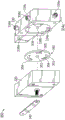
Fig. 1A-1C illustrate a configuration of an air management system for a vehicle, as disclosed herein, indicated by reference numeral 100. The air manager assembly 100 includes a first pneumatic circuit disposed on a first side of the vehicle 1, a second pneumatic circuit disposed on a second side of the vehicle 1, and a cross-flow line 38 pneumatically connecting the first and second pneumatic circuits. The vehicle 1 may have front-and rear-driven and/or non-driven wheeled axles 2 and 3, which axles 2 and 3 are supported on the chassis 1 in a known manner by means of pairs of springs (also interchangeably referred to as air springs) 4-5, 6-7, 8-9 and 10-11 positioned on both sides of the axles 2 and 3 as shown. The present invention is not limited to having the particular number of axles, air bags (air springs), air lines/hoses, air supply tanks shown in the drawings, as these elements vary depending on the type of vehicle used, as will be apparent to those skilled in the art. In another example, the first and second pneumatic circuits may be supplied with air from a common air supply tank, such that the air management system 100 includes only one air supply tank to provide air flow to the air springs 4-11 on both sides of the vehicle 1.
In fig. 1A-1C, air springs 4, 5, 8, and 9 are positioned on a first side of vehicle 1 and connected together by individual air lines 12, 13, and 18-21 to form a first set of air springs. The air springs 4, 5, 8 and 9 and the individual air lines 12, 13 and 18-21 are supplied with air via a valve hose 28, which is connected to the first leveling valve 16. A supply hose 30 extends from the first leveling valve 16 directly to a first supply tank 32 for supplying air to the first leveling valve 16. The supply hose 30 is also provided with a pressure protection valve 34. Thus, the air springs 4, 5, 8, and 9; individual air lines 12, 13 and 18-21; a valve hose 28; a first leveling valve 16; a supply hose 30; a pressure protection valve 34 (not required in some vehicles or air management systems); and the first supply tank 32 form a first pneumatic circuit adapted to independently adjust the height of the first side of the vehicle 1.
In some aspects (not shown), the air management assembly 100 may include a single air supply tank for delivering air to both the first and second pneumatic circuits simultaneously and a single pressure protection valve connected to the air supply tank by a single hose and to the first and second pneumatic circuits by two supply hoses. The single pressure protection valve is configured to supply sufficient air pressure to both the first pneumatic circuit and the second pneumatic circuit in the event of a leak or fault within the air management system 100. The single pressure protection valve is configured to have a greater air capacity for the pressure protection valve 34 in order to provide sufficient air to both the first and second pneumatic circuits simultaneously.
Air springs 6, 7, 10 and 11 are positioned on a second side of vehicle 1 and connected together by separate air lines 14, 15 and 22-25 to form a second set of air springs. The air springs 6, 7, 10 and 11 and the individual air lines 14, 15 and 22-25 are supplied with air via a valve hose 29, which is connected to the second leveling valve 17. The supply hose 31 extends from the second leveling valve 17 directly to a second supply tank 33 for supplying air to the second leveling valve 17. The supply hose 31 is also provided with a pressure protection valve 35. Thus, the air springs 6, 7, 10, 11, the individual air lines 14, 15, and 22-25, the valve hose 29, the second leveling valve 17, the supply hose 31, the pressure protection valve 35, and the second supply tank 33 form a second pneumatic circuit adapted to independently adjust the height of the second side of the vehicle 1. Both the first and second pneumatic circuits are independently operable such that the first leveling valve 16 independently delivers air to or bleeds air from a first side of the vehicle 1 and the second leveling valve 17 independently delivers air to or bleeds air from a second side of the vehicle 1.
To ensure a balanced supply of air to each air spring of substantially the same volume and pressure, the individual air lines 12, 13 and 18-21 on the first side on the vehicle 1 and the individual air lines 14, 15 and 22-25 on the second side on the vehicle 1 are of substantially the same size (inside diameter) and length. In the configuration shown, the individual air lines 18-21 and 22-25 each have a bore diameter of about 12mm (1/2 inch). Other sizes may be used and similar results achieved, so long as the size and length of the air lines in each group or group (e.g., 18-25, 28 and 29, 30 and 30, 31, etc.) are the same. For similar reasons, the valve hoses 28 and 29 have substantially the same size or inner diameter and length, and the supply hoses 30 and 31 have substantially the same size or inner diameter and length. The provision of separate air lines 18-21 and 21-25 and the connection of these lines to the separately supplied leveling valves 16 and 17 ensures that an equal volume of air is rapidly supplied to each of the air springs so that the internal pressure of the air springs responds appropriately to changes in road conditions relayed to the valves 16 and 17. Thus, the rate of change of the internal pressure to the first set of air springs is substantially symmetric with the rate of change of the internal pressure to the second set of air springs.
The first control valve 16 and the second control valve 17 each comprise a control arm 16a, 17a, which control arms 16a, 17a are connected to a rigid rod 36 mounted below the air springs 9 and 11. The control arms 16a, 17a are each configured to move up and down in response to compression and extension of the air spring, which actuates the first and second control valves 16, 17 to supply air to or bleed air from the air spring. When the control arms 16a, 17a are in the neutral position, both the first leveling valve 16 and the second leveling valve 17 neither supply air from the supply tank to the air springs nor remove air from the air springs to the atmosphere. A cross-flow line 38 extends from the first leveling valve 16 to the second leveling valve 17 to connect the first leveling valve and the second leveling valve. As shown in fig. 1A, the cross-flow line 38 is not directly connected to the supply lines 30, 31 or the air supply tanks 32, 33. When both control arms 16a, 17a are in the neutral position, the first leveling valve 16 and the second leveling valve 17 are in pneumatic communication with each other, so that there is pneumatic communication between the first and second pneumatic circuits via the cross flow line 38, thereby equalizing the air pressure between the air springs 4, 5, 8 and 9 on the first side of the vehicle 1 and the air springs 6, 7, 10, 11 on the second side of the vehicle. As a result, when both control arms 16a, 17a are in the neutral position, the first and second pneumatic circuits are connected together as a common circuit. By maintaining equal air pressure between the first and second sets of air springs, the first and second leveling valves 16, 17 equalize the pressure between the two sides of the vehicle when both control arms 16a, 17a are in the neutral position. In the aspect shown, only a single cross-flow line 38 is required to establish pneumatic communication between the first and second pneumatic circuits such that air flows between the left and right sides of the vehicle.
The first leveling valve 16 and the second leveling valve 17 are allowed to pneumatically communicate with each other via the cross-flow line 38 only when both of the control arms 16a, 17a are in the neutral position. In other words, the first and second leveling valves 16a, 17a prevent pneumatic communication between the first and second pneumatic circuits when either of the control arms 16a, 17a is not in the neutral position. By not establishing pneumatic communication between the first and second pneumatic circuits when either of the control arms 16a, 17a moves up and down from the neutral position, the first and second leveling valves 16, 17 can independently bleed air from or supply air to the air springs. Therefore, when the vehicle 1 is making a sharp turn by shifting the center of gravity of the vehicle, without any cross flow between the first leveling valve 16 and the second leveling valve 17, one of the first leveling valve 16 and the second leveling valve 17 supplies air to the spring group that has contracted due to the shift of the center of gravity of the vehicle 1, while the other of the first leveling valve 16 and the second leveling valve 17 bleeds off air from the other spring group that has extended due to the shift of the center of gravity of the vehicle. In this state, the first and second leveling valves 16 and 17 may overcompensate for the dynamic center of gravity shift of the vehicle due to supplying too much air to one set of air springs or removing too much air from the other set of air springs, resulting in a slight pressure difference between the first and second sets of air springs. Without the mechanism described in this disclosure, this slight pressure differential between the first and second sets of air springs may not trigger any of the control arms 16a, 17a to pivot away from the neutral position when the vehicle 1 is moving away from a turn, which would place the vehicle 1 in a non-level condition. According to the present disclosure, since the first and second leveling valves 16, 17 communicate with each other via the cross flow 38 when both control arms 16a, 17a are in the neutral position, when air advances from the spring set at the higher pressure to the spring set at the lower pressure via the cross flow line 38, the slight pressure difference between the first and second sets of air springs is eliminated, thereby achieving the equilibrium state.
Fig. 2 schematically illustrates a leveling valve 50 according to one configuration of the present invention. The leveling valve 50 includes a housing 60 and a control arm 70. The housing 60 includes a supply port 61 connected to a supply tank, a drain port 62 connected to atmosphere, an air spring port 63 connected to an air spring on one respective side of the vehicle, and a cross flow port 64 connected to a second leveling valve on the other side of the vehicle. Although FIG. 2 shows the housing 60 having one air spring port, the housing 60 may include two or more air spring ports to communicate with sets of air springs disposed on respective sides of the vehicle. Further, the relative positioning of the ports with respect to each other and to the control arm may vary and is not intended to be limited to the configuration shown in fig. 2.
As shown in FIG. 2, the control arm 70 is connected to the housing 60 and pivots about the housing 60 between a plurality of positions in response to compression and extension of an air spring disposed on one side of the vehicle. When the air spring compresses, the control arm 70 pivots upward from the horizontal position to the first position, which establishes communication between the supply port 61 of the housing and the air spring port 63. Accordingly, air is supplied from the supply tank to the respective air springs, thereby increasing the air pressure of the air springs. When the respective air spring is extended, the control arm 70 pivots downward from the horizontal position to a second position, which establishes communication between the exhaust port 62 of the housing 60 and the air spring port 63. Thus, air is removed from the air spring and released to the atmosphere, thereby reducing the air pressure of the air spring. When the control arm 70 pivots away from the neutral position in either direction, the air spring port 63 does not communicate with the cross flow port 64. In the neutral position, the control arm 70 is oriented in a substantially horizontal position such that the control arm 70 extends parallel to the ground. When the control arm 70 is set in the neutral position, the air spring port 63 is not communicated with either the supply port 61 or the exhaust port 62. In contrast, when the control arm 70 is disposed at the neutral position, the air spring port 63 communicates with the cross flow port 64, so that the leveling valve 50 can communicate with another leveling valve disposed on the opposite side of the vehicle (as shown in fig. 1A to 1C).
According to one exemplary configuration, the leveling valve may include a rotating member (not shown), such as a disk, received in a central bore (not shown) of the housing, wherein the central bore is pneumatically connected to each port of the housing. The rotating member is rotatably connected to the control arm such that pivotal movement of the control arm causes rotation of the rotating member. The rotating member may be rotated between a plurality of positions to vary communication between the ports of the housing. Each leveling valve is a symmetric dynamically balanced volume and pressure distribution valve having at least one rotating member (not shown) with different sized grooves or through holes to either deliver or bleed air to the air spring when actuated in a responsive position, or shut off air flow to the bleed and supply ports when actuated in a neutral position and open pneumatic communication at the cross flow ports when in a neutral position. Thus, if the leveling valve on one side of the vehicle is in a neutral position, but the leveling valve on the opposite side of the vehicle is not in a neutral position, there is no pneumatic communication between the two leveling valves. Pneumatic communication is established between the pneumatic circuits on opposite sides of the vehicle only when both leveling valves are actuated to a neutral position.
Establishing the cross flow when none of the leveling valves independently adjusts the height of the respective side of the vehicle mitigates unbalanced pressure differences between the air springs on each side of the vehicle. It has been found that one factor contributing to these pressure differences is gravity. For example, when the vehicle is passing a turn and experiences a dynamic lateral center shift, one of the leveling valves responds by supplying air to the compressed air springs while the other of the leveling valves removes air from the extended air springs. However, a leveling valve that supplies air in response to a lateral center of gravity shift tends to supply air with a force greater than the gravitational force acting on the compression spring. As a result, the leveling valve typically supplies more air to the air springs of its group than the volume of air removed from the other groups of air springs on the opposite side of the vehicle. While the pressure differential remains between the air springs on the opposite side of the vehicle, the control arm returns to a horizontal neutral position in which the supply and drain ports of each leveling valve are closed (e.g., in the no-control-active-zone position), thereby not allowing for overcompensated air being supplied to one of the air springs of the set.
The air management system of the present invention provides the unexpected advantage of mitigating the pressure differential between the air springs on each side of the vehicle by connecting at least two independent pneumatic circuits to form a common pneumatic circuit when both leveling valves are in neutral mode. In this context, the leveling valve is in "neutral mode" when the leveling valve neither supplies air from the air supply tank nor vents air to the atmosphere. Thus, the air management system of the present disclosure may independently adjust each side of the vehicle by preventing communication between the first and second pneumatic circuits when at least one of the leveling valves is not in the neutral mode. The air management system of the present invention may also connect the first and second pneumatic circuits to a common circuit by establishing cross-flow communication between the first and second pneumatic circuits when both leveling valves are in neutral mode. Establishing a cross flow between the air springs on each side of the vehicle allows the overcompensated air springs with greater pressure to release air to the air springs on the other side of the vehicle via a cross flow line, thereby promoting balance between the air springs on both sides of the vehicle. Finally, the ability to selectively provide cross flow when all leveling valves are set in neutral mode allows the air management system to better traction maintain a highly stable, safer, and more comfortable vehicle ride.
Fig. 3 and 4 show different views of a mechanically actuated valve according to one configuration of the present invention. The leveling valve 300 shown in fig. 3 and 4 includes a valve body 310 including an upper housing 320 mounted to a lower housing 330, with a control arm 340 attached to a shaft extending through the upper housing 320. The upper housing 320 is mounted to the lower housing 330 by fasteners (not shown) that are received in mounting holes extending through the corners of the upper and lower housings 320, 330.
Referring to fig. 4 and 5, the lower housing 330 includes at least five ports 334a to 334e, including a supply port 334a connected to an air tank (not shown), a discharge port 334b for bleeding air from air springs (not shown), a first port 334c connected to a first set of air springs (not shown), a second port 334d connected to a second set of air springs (not shown), and a cross flow port 334e connected to another leveling valve (not shown). The first port 334c and the second port 334d are arranged such that the first spring port 334c on one side of the lower housing 330 and the second spring port 334d on the other side of the lower housing 330 coincide. The ports 334a to 334d are also arranged such that the supply port 334a on one side of the lower housing 330 coincides with the discharge port 334b on the opposite side of the lower housing 330.
The lower housing 330 includes a separate air flow passage (not shown) to each port 334a to 334e of the lower housing 330 such that air supplied from the supply port 334a or air bled to the discharge port 334b occurs independently of air flowing through the cross flow port 334 e. Referring to fig. 5, the lower housing 330 includes a first surface 336 defining a plurality of circular lumens 338 a-338 c. The supply port 334a is connected to the supply chamber 338a through one air flow passage formed in the lower case 330, and the discharge port 334b is connected to the discharge chamber 338b through a second air flow passage formed in the lower case 330. The cross flow port 334e is connected to the cross flow chamber 338c through a third air flow passage formed in the lower case 330. The first and second spring ports 334c and 334d may be connected by a reservoir chamber (not shown) formed in the lowered housing 330.
Fig. 4 and 6A-6C illustrate a rotating disk 350 according to one configuration of the present invention. Referring to fig. 4, the rotating disk 350 is received in a central hole defined between the lower case and the upper case. The rotary disk 350 includes a central aperture 352 configured to rotatably receive a post (not shown) extending from the lower housing 330 and through the upper housing 320 to connect to the control arm. The rotary disk 350 is configured to rotate about a post (not shown) within the central bore of the lower housing 330, thereby defining the central aperture 352 as a pivot point. The rotary disk 350 includes two oblong slots 354 spaced around a central aperture 352 with a disk surface 353 defined therebetween and along the periphery of the rotary disk 350. The disk surface 353 corresponds to an area of the rotary disk 350 that includes only the solid surface of the rotary disk 350, and does not include any void space defined by the slots. Thus, when the disk surface 353 of the rotating disk 350 completely overlaps the corresponding cavity, airflow is restricted from entering through the corresponding cavity. The carousel 350 also includes a cross-flow slot 355 that is smaller than the two oblong slots 354.
The angular position of the rotary disk 350 changes as the control arm 340 pivots about the valve body 310 of the valve 300. As shown in fig. 6A, when the control arm 340 is set to the horizontal position, the rotating disk 350 is set to the neutral position in which the disk surface 353 of the rotating disk 350 covers the supply chamber 338a and the discharge chamber 338b of the lower case 330. Thus, at the neutral position, the rotary disk 350 is disposed within the no-control-action-zone rotation range. Therefore, when the rotary disk 350 is disposed at the neutral position, the air spring is connected to neither the supply port 334a nor the discharge port 334 b. However, the cross flow slot 355 covers the cross flow cavity such that the first and second springs communicate with the cross flow port 334 e. As shown in fig. 6B, due to the clockwise rotation of the control arm 340, the rotary disk 350 rotates to an angular position: wherein the arrangement of slots 354, 355 connects the supply chamber 338a with a reservoir chamber (not shown) such that the air spring receives air from the supply tank, thereby increasing the air pressure of the air spring. As shown in fig. 6C, due to the counterclockwise rotation of the control arm 340, the rotary disk 350 rotates to an angular position: the arrangement of slots 354, 355 connects the exhaust chamber 338b with a reservoir chamber (not shown) so that air is removed from the air spring to atmosphere. In other configurations, one condition of clockwise movement of one rotating disk 350 may correspond to counterclockwise rotation of the other rotating disk 350 in accordance with the present invention. For example, a clockwise rotation of the rotary arm may cause the rotary disk 350 to rotate to an angular position: wherein the arrangement of slots 354, 355 connects the exhaust chamber 338b with a spring reservoir chamber (not shown) such that the air spring vents air to atmosphere, thereby reducing the air pressure of the air spring. Further, a counter-clockwise rotation of the rotary arm may cause the rotary disk to rotate to an angular position: wherein the arrangement of slots 354, 355 connects the supply chamber 338a with a spring reservoir chamber (not shown) so that air is supplied from the supply tank to the air springs.
Fig. 10, 11 and 12A-12C illustrate a lower housing 430 according to one configuration of the present invention. The lower housing 430 is configured to be mounted to the upper housing 320 shown in fig. 3 and 4 to form a valve body of the leveling valve. Similar to the configuration shown in fig. 3-5, the lower housing 430 includes at least five ports 434 a-434 e, including a supply port 434a connected to an air tank (not shown), a discharge port 434b for bleeding air from the air springs (not shown), a first port 434c connected to a first set of air springs (not shown), a second port 434d connected to a second set of air springs (not shown), and a cross-flow port 434e connected to another leveling valve (not shown). The lower housing 430 may also optionally include a sixth port 434f (shown in fig. 12A and 12B) connected to a dump valve (not shown) configured to simultaneously remove all air from each air spring of the air management system.
As shown in fig. 12A to 12C, the lower housing 430 includes separate air flow passages leading to each port 434a to 434f, including a supply passage 432A connected to the supply port 434a, a discharge passage 432b connected to the discharge port 434b, a first passage 432C connected to the first port 434C, a second passage 432d connected to the second port 434d, a cross flow passage 432e connected to the cross flow port 434e, and a dump passage 432f connected to the dump port 434 f. Lower housing 430 includes a first surface 436 defining a plurality of circular blind bores 438 a-438 c and a reservoir chamber 439. The blind holes 438a to 438c include a supply hole 438a connected to the supply port 434a through the supply passage 432a, a discharge hole 438b connected to the discharge port 434b through the discharge passage 432b, and a cross flow hole 438c connected to the cross flow port 434e through the cross flow passage 432 e. The lower housing 430 also includes a central aperture 438d configured to receive a post (not shown) extending through the upper housing 320 to receive a control arm. The first passage 432c, the second passage 432d and the dump passage 432f are interconnected together and extend from the reservoir chamber 439. In one example shown in fig. 10, lower housing 430 may include a raised surface 437 protruding from first surface 436, wherein apertures 438 a-438 c and chamber 439 are defined along raised surface 437. The raised surface 437 of the lower housing 430 is configured to engage the lower surface of the upper housing 320 to define a chamber therein.
FIG. 13 shows a rotating disk 450 according to one configuration of the present invention. Similar to the configuration shown in fig. 4 and 6A-6C, the rotating disk 450 includes a central aperture 452, two oblong slots 454, and a cross-flow slot 455 with a disk surface 453 extending therebetween and along the perimeter of the rotating disk 450. The central aperture 452 is disposed between the two oblong slots 454 and the cross-flow slot 455. 33 3 the 33 3 two 33 3 oblong 33 3 slots 33 3 454 33 3 are 33 3 symmetrically 33 3 spaced 33 3 about 33 3 the 33 3 central 33 3 axis 33 3 a 33 3- 33 3 a 33 3 of 33 3 the 33 3 rotating 33 3 disk 33 3 455 33 3 and 33 3 the 33 3 cross 33 3 flow 33 3 slot 33 3 455 33 3 covers 33 3 the 33 3 central 33 3 axis 33 3 a 33 3- 33 3 a 33 3 of 33 3 the 33 3 rotating 33 3 disk 33 3 450 33 3 with 33 3 the 33 3 central 33 3 aperture 33 3 452 33 3 disposed 33 3 between 33 3 the 33 3 oblong 33 3 slots 33 3 454 33 3 and 33 3 the 33 3 cross 33 3 flow 33 3 slot 33 3 455 33 3. 33 3 The cross-sectional area of the cross-flow slot 455 is substantially less than the cross-sectional area of each rectangular slot 454. For example, the cross-sectional area of the cross-flow slot 455 is at most one-third, one-fourth, one-fifth, one-tenth, one-twentieth, one-thirtieth, one-forty or less of the cross-sectional area of the rectangular slot 454. In some non-limiting aspects (e.g., fig. 33-36), the width or diameter of the cross-flow slot 455 may vary across its depth such that the width or diameter of the cross-flow slot 455 has a first lateral dimension at a first face of the rotating disk 450 and a second lateral dimension at a second face of the rotating disk 450, wherein the first lateral dimension is greater than the second lateral dimension.
The rotary disk 450 is received onto the raised surface 437 of the lower housing 430 and the central aperture 452 receives a shaft (not shown) extending from the first surface 436 of the lower housing 430 of the rotary valve to the upper housing (not shown). Similar to the configuration shown in fig. 4 and 6A-6C, rotary plate 450 is configured to rotate about an axis between a plurality of positions including a neutral position, a first angular position, and a second angular position. In the neutral position, the disc surface 453 of the rotary disc 450 covers both the supply hole 438a and the discharge hole 438b of the lower housing 430, so that the air spring is connected to neither the supply port 434a nor the discharge port 434 b. Therefore, when set at the neutral position, the rotary disk 450 is set within the no-control-action-region rotation range. In the neutral position, the cross flow slot 455 overlies the cross flow hole 438c such that the first and second springs are in communication with the cross flow port 434 e.
When the rotary plate 450 is rotated in a clockwise direction away from the neutral position to a first angular position, the oblong slot 454 connects the supply aperture 438a with the reservoir chamber 439 such that the air spring receives air from the supply tank, thereby increasing the air pressure of the air spring. When the rotating plate 450 is disposed in the first angular position, the cross flow slot 455 rotates away from the cross flow hole 438 such that the non-control action region 453 covers the cross flow hole 438 c. When the rotary plate 450 is rotated in the counterclockwise direction away from the neutral position to the second angular position, the oblong slot 454 connects the discharge hole 438b with the reservoir chamber 439 so that air is removed from the air spring. When the rotating disk 450 is disposed in the second angular position, the cross-flow slot 455 rotates away from the cross-flow aperture 438c such that the uncontrolled zone 453 covers the cross-flow aperture 438 c.
Due to the sizing of the cross flow slots 455, the rotating disk 450 need only rotate slightly about 1 ° to 2 ° clockwise or counterclockwise from the neutral position, and the uncontrolled zone 453 completely covers the cross flow aperture 438 c. Thus, the rotating disk may quickly transition from allowing cross flow between the first and second pneumatic circuits to independently control airflow to one side of the vehicle without cross flow occurring. When the rotary disk is rotated about 1 ° to 2 ° in the clockwise or counterclockwise direction from the neutral position, the oblong slot 454 is not communicated with the supply hole 438a and the discharge hole 438b of the lower housing 430. When the rotational speed of the rotating disk exceeds a predetermined threshold speed, the rotating disk 450 may rotate from the first angular position to the second angular position without allowing air to flow through the cross flow holes 438c and the cross flow ports 434e during the transition. Thus, when the vehicle experiences a subsequent dynamic center of gravity shift, the rotating disk may switch between supplying air to and removing air from the air springs without allowing cross flow to occur between the first and second pneumatic circuits during the transition.
Fig. 14A and 14B illustrate a first poppet 460 according to one configuration of the present invention. The first poppet 460 includes a cylindrical body 462 that extends from a first end 464 to a second end 466. The first poppet 460 includes a passage 463 extending through the body 462 from a first opening 463a defined along the first end 464 to a second opening 463b defined along the second end 466. The size of the first opening 463a is equal to the size of the second opening 463 b. The first poppet valve 460 is disposed in both the supply and drain holes 438a, 438b of the lower housing 430 with the first end 464 protruding from the first surface 436 of the lower housing 430 and engaging the rotary disk 450 to provide an air-tight seal between the supply and drain holes 438a, 438b and the oblong slot 454. In some other configurations (not shown), the size of first opening 463a may be different than the size of second opening 463b, such that the diameter or width of channel 463 varies across its length. In one example, first opening 463a may include a first diameter and second opening 463b may include a second diameter, where the second diameter is smaller than the first diameter.
Fig. 15A and 15B illustrate a second poppet 470 according to one configuration of the present invention. Similar to the first poppet 460, the second poppet 470 includes a cylindrical body 472 extending from a first end 474 to a second end 476. The first poppet 470 includes a passage 473 extending through the body 472 from a first opening 473a defined along the first end 474 to a second opening 473b defined along the second end 476. Unlike the first poppet 460, the first opening 473a in the second poppet 470 is smaller in size than the second opening 473 b. The size and shape of the first opening 473a of the second poppet 470 corresponds to the size and shape of the cross-flow slot 455 in the rotating disk 450. The second poppet 470 is disposed in the cross-flow aperture 438c of the lower housing with the first end 474 protruding from the first surface 436 of the lower housing 436 and engaging the rotating disk 450 to provide an air-tight seal between the cross-flow slot 455 of the rotating disk 450 and the cross-flow aperture 438 c.
In one non-limiting aspect, the lower housing 430 may include a fourth blind bore (not shown) disposed along the first surface 436, whereby the fourth blind bore is aligned with the cross-flow bore 438c, and a reservoir chamber 439 is disposed between the fourth blind bore and the cross-flow bore 438 c. In some aspects, the fourth blind bore is ninety degrees to the supply and drain holes 438a, 438b relative to the central bore 438d and one hundred and eighty degrees to the cross-flow hole 438c relative to the central bore 438 d. The fourth blind hole is not in pneumatic communication with any one of the supply passage 432a, the discharge passage 432b, the first passage 432c, the second passage 432d, the cross-flow passage 432e, and the dump passage 432 f. In some aspects, a third poppet (not shown) may be disposed in the fourth blind bore. In some aspects, the third poppet may include the same configuration as the first poppet 460 received in the cross-flow bore 438c such that the third poppet includes a first end configured to protrude above the first surface 436 of the lower housing 430. When the rotary disk 450 is received on the first surface 436 of the lower housing 430, the third poppet is configured to engage the rotary disk 450 such that the bottom surface of the rotary disk 450 engages the four poppet valves, a pair of first poppet valves 460 received in the supply and drain holes 438a and 438b, a second poppet valve 470 received in the cross-flow bore, and the third poppet valve received in the fourth blind bore. The rotary disk 450 is maintained in a horizontal position by engaging four poppet valves each displaced ninety degrees relative to the central bore 438 d.
FIG. 43 illustrates a relationship between the angle of the control arm and the air pressure at various ports of the lower housing of the leveling valve in accordance with an exemplary aspect of the present invention. As shown in fig. 43, the x-axis reflects the time of the motorized operation in seconds, and the y-axis indicates the angle of the control arm in degrees (i.e., represented by a solid line) and the air pressure of the respective valve port in response to the changing control arm angle in pressure Per Square Inch (PSIG) (represented by a dotted or dashed line). Referring to fig. 43, as the vehicle dynamically encounters changing road conditions, i.e., as the control arm initially pivots away from the neutral position as indicated by the x-axis, the air pressure at the work port (i.e., the spring port connected to the air spring) increases exponentially while the air pressure at the supply port decreases slightly. Thus, the leveling valve is configured to respond quickly to supply air pressure to the air spring when the control arm is pivoted away from the neutral position to the supply position. Then, as indicated at about 14 seconds on the x-axis in fig. 43, as the control arm initially pivots back toward the neutral position, the air pressure at the spring port is maintained at a constant level. Once the leveling arm returns to the neutral position, as indicated at about 28 seconds on the x-axis in fig. 43, the air pressure at the cross-flow port spikes to about 90PSIG, and the air pressure at the spring port decreases slightly. As a result, the pressure in the connected air springs is slightly reduced, so that the air springs disposed on the opposite sides of the vehicle become equal. Then, as the vehicle continues to travel and encounters different changing road conditions, i.e., as the control arm rotates in the opposite direction away from the neutral position, beginning at about 29 seconds on the x-axis in fig. 43, the air pressure at the exhaust port increases such that the air pressure at the spring port exponentially decreases at a faster rate than the decrease in air pressure when the control arm is set in the neutral position. Thus, in response to the control arm switching to the exhaust position, the air pressure in the connected air spring is significantly reduced. Thus, fig. 43 illustrates that the leveling valve according to the present invention operates according to three distinct phases: (i) a supply mode, (ii) a drain mode, and (iii) a cross-flow mode. Further, fig. 43 illustrates that there is no bleed over between the separate stages, such that the leveling valve may only operate in one of the three modes at a single time.
According to various aspects, fig. 44 illustrates a method 900 for adjusting air pressure of an air management system 100 including one or more air supply tanks 32, 33, a first pneumatic circuit disposed on a first side of a vehicle and a second pneumatic circuit disposed on a second side of the vehicle. As shown in fig. 44, method 900 includes a step 910 of independently adjusting an air pressure of the first pneumatic circuit via the first leveling valve 16. In various aspects, independently adjusting the air pressure of the first pneumatic circuit includes supplying air to the first pneumatic circuit from one or more air supply tanks 32, 33 or removing air from the first pneumatic circuit to the atmosphere. As shown in fig. 44, method 900 includes a step 920 of independently adjusting the air pressure of the second pneumatic circuit via the second leveling valve 17. In various aspects, independently adjusting the air pressure of the second pneumatic circuit includes supplying air to the second pneumatic circuit from one or more air supply tanks 32, 33 or removing air from the second pneumatic circuit to the atmosphere. As shown in fig. 44, method 900 includes a step 930 of establishing pneumatic communication between the first pneumatic circuit and the second pneumatic circuit only when both the first leveling valve 16 and the second leveling valve 17 are set in the neutral mode. In various aspects, the leveling valve in neutral mode neither supplies air from the one or more air supply tanks nor removes air to the atmosphere.
The air management system may include a mechanically or electronically actuated leveling valve to control communication between the first pneumatic circuit and the second pneumatic circuit. In one exemplary configuration, the air management system may include a leveling valve disposed at each air spring, wherein each leveling valve includes a manifold and a plunger disposed in a chamber of the manifold. The plunger is configured to move in the chamber of the manifold between one or more positions including at least a first position for establishing cross-flow between the first and second pneumatic circuits and a second position for independently adjusting the height of the respective side of the vehicle. Rather than having a control arm for actuating the air flow, the manifold may include an electronic actuator for moving the plunger between one or more positions so that the air flow can be supplied or removed from the respective air spring. In one exemplary configuration, the air management system may have a central manifold that includes a respective port connected to each air spring of the air management system.
In one example configuration, the leveling valve may include one or more solenoid valves that allow air to be independently adjusted to each side of the vehicle while selectively allowing cross flow between the first and second pneumatic circuits to equalize pressure between the first and second sets of air springs. The air management system may also include a controller in electrical communication (e.g., wireless or wired) with the leveling valve to control operation of the electronically actuated leveling valve. The air management system may also include an air pressure sensor disposed in the air line to sense pressure changes and imbalances and communicate such data to a controller in electrical communication (e.g., wireless or wired) with the leveling valves or to one or more of the leveling valves themselves. The air management system may also include inputs based on ride height sensors for height control, flow sensors at one or more of the ports and in communication with electronic systems, such as any electronic stability control system (ESC), including but not limited to the Electronic Stability Program (ESP), dynamic stability control system (DSC), vehicle stability control system (VSC), automatic traction control system (ATC), and/or roll stability control system (RSC) of the vehicle 1. Connecting the actuation of the air management system to a controller that is also connected to the ESC, ESP, DSC, VSC, ATC or RSC of the vehicle improves the overall safety of the vehicle by synchronizing the braking and steering control with the operation of the air management system.
In various configurations, the controller of the air management system is in electrical communication with the leveling valve, sensors, and other vehicle electrical systems (e.g., ESC, ESP, DSC, VSC, ATC, etc.). In various aspects, the controller may receive measurement signals sent from sensors, such as height and pressure measurements of the air springs. Based on the measurement signals and the data signals, the controller is configured to calculate a current state of each air spring of the air management system and a dynamic operating state of the vehicle. In one configuration, the controller is configured to calculate a pressure or height difference between air springs of the air management system based on the received measurement and data signals. The controller is configured to actuate the valve to an active mode when a pressure or height difference between the air springs is above a predetermined threshold, and to actuate the valve to a neutral mode when the pressure or height difference is below the predetermined threshold. Thus, when there is a substantial height difference between the respective sides of the vehicle, the controller is configured to send commands to the leveling valves to independently adjust the height of the air springs of their respective pneumatic circuits to level the vehicle at a faster rate. In various aspects, the controller may send commands to operate the leveling valve in the active mode at any vehicle speed. When there is only a slight height difference between the respective sides of the vehicle that does not trigger a roll condition, the controller is configured to send a command to place the leveling valve in neutral mode and relieve any pressure differential between the air springs by establishing a cross flow between the air springs. In various aspects, the controller sends commands to operate the leveling valve in the neutral mode at any vehicle speed (including speeds substantially above zero miles per hour or zero kilometers per hour).
Fig. 7-9 illustrate an air management system including a series of air lines, wherein the lengths of all of the air lines extending between the respective air springs and control valves are of equal length and internal diameter. Fig. 7 shows an air management system 200a that includes a first pneumatic circuit, a second pneumatic circuit, and at least two leveling valves 300 a. Each pneumatic circuit includes one or more air springs 205a, an air supply tank 210a, a supply line 220a extending between the leveling valve 300a and the supply tank 210a, and a set of transfer lines 230a connecting the one or more air springs 205a to the leveling valve 300 a. The air management system 200a also includes a pressure protection valve 240a connected to each supply line 220a (not required for all air management systems). In some configurations of the air management system 200a, the transfer lines 230a may have equal lengths and diameters, and the supply lines 220a may have equal lengths and diameters. Each leveling valve 300a is mechanically actuated by a control arm 305 and is configured to independently adjust the flow of air to one of the first or second pneumatic circuits. The leveling valves 300a are connected together by a cross-flow line 250a to establish fluid communication between the first and second pneumatic circuits when all of the leveling valves are set in neutral mode. Thus, the leveling valve 300a is configured to provide a cross flow between the first and second pneumatic circuits when air is neither supplied to the air springs from the air tank nor removed from the air springs to the atmosphere.
Fig. 8 shows an air management system 200b that includes a first pneumatic circuit, a second pneumatic circuit, and at least two leveling valves 300 b. Each pneumatic circuit includes one or more air springs 205b, an air supply tank 210b, a supply line 220b extending between the leveling valve 300b and the supply tank 210b, and a set of transfer lines 230b connecting the one or more air springs 205b to the leveling valve 300 b. In some configurations of the air management system 200b, the transfer lines 230b may have equal lengths and diameters, and the supply lines 220b may have equal lengths and diameters. The air management system 200b also includes a pressure protection valve 240b connected to each supply line 220 b. As shown in fig. 8, the leveling valve 300b is an electronically actuated leveling valve connected together by a cross flow line 250 b. The electronically actuated leveling valve is configured to provide a cross flow between the first and second pneumatic circuits when air is neither supplied to the air spring from the air tank nor removed from the air spring to atmosphere (i.e., in a neutral mode).
Fig. 9 illustrates an air management system 200c that includes a first pneumatic circuit, a second pneumatic circuit, and at least two leveling valves 300 c. The air management system 200c includes one or more air springs 205c, a supply air tank 210c connected to each leveling valve 300c by a respective supply line 220c, with a pressure protection valve 240c incorporated into the supply line 220 c. Each leveling valve 300c is connected to one or more air springs 205c by a series of transfer lines 230 c. In some configurations of the air management system 200c, the transfer lines 230c may have equal lengths and diameters, and the supply lines 220c may have equal lengths and diameters. The leveling valves 300c are connected together by a cross flow line 250 c. As shown in fig. 9, the leveling valve 300c is an electronically actuated leveling valve and is in electrical communication with the control unit 260. The electrical communication may be established through a wired connection or a wireless connection. The electronically actuated leveling valve is configured to provide a cross flow between the first and second pneumatic circuits when air is neither supplied to the air spring from the air tank nor removed from the air spring to atmosphere (i.e., in a neutral mode).
Fig. 16-18 illustrate an air management system utilizing an electronic control unit to synchronously control air flow. Fig. 16 shows an air management system 500a that includes a first pneumatic circuit 510a, a second pneumatic circuit 520a, and at least two leveling valves 600 a. Each pneumatic circuit 510a, 520a includes one or more air springs 530 a. Each leveling valve 600a is configured to independently adjust the flow of air to one of the first pneumatic circuit or the second pneumatic circuit. The leveling valves 600a are connected together by a cross-flow line 550a to establish fluid communication between the first pneumatic circuit 510a and the second pneumatic circuit 520a when all of the leveling valves 600a are set in the neutral mode. Each leveling valve 600a is mechanically actuated by a control arm 610 and includes a control arm sensor (not shown) disposed in the housing of the leveling valve 600a to detect the position of the control arm. In one example, the control arm sensor may be a potentiometer. The control arm sensor is in electrical communication with a control unit 650a, which may be integrated into the ESC, ESP, DSC, VSC, ATC, or RSC of the vehicle. The electrical communication may be established through a wired connection or a wireless connection. The control arm sensor is configured to detect the position of the control arm and send the position of the control arm as a control arm position input to the control unit 650 a. The control unit 650a is configured to determine a vehicle height of a respective side of the vehicle based on the control arm position input.
Fig. 17 shows an air management system 500b that includes an air supply tank 505b, a first pneumatic circuit 510b connected to the supply tank 505b, a second pneumatic circuit 520b connected to the supply tank 505b, and at least two leveling valves 600b, wherein each leveling valve is configured to independently control air flow to one of the first pneumatic circuit 510b or the second pneumatic circuit 520 b. In other configurations of the air management system 500b, the air management system may have more than one air supply tank 505 b. Each pneumatic circuit 510b, 520b includes one or more air springs 530 b. Each leveling valve 600b includes a valve element (not shown) configured to move between a plurality of positions including a neutral position, a supply position, and a drain position. In one example, the valve element may be a poppet valve, plunger, or the like. When the valve element is set in the neutral position, the port neither supplies air from the air tank to the air spring nor removes air from the air spring to the atmosphere. Each leveling valve 600b is electronically actuated by an electronic actuator 620. In one example, the electronic actuator 620 can be a solenoid, motor, or the like. As shown in fig. 17, the leveling valves 600b are connected together by a cross-flow line 550b to establish fluid communication between the first pneumatic circuit 510b and the second pneumatic circuit 520b when all of the valve elements are disposed in the neutral position. The air management system also includes a plurality of leveling sensors 630, including at least one leveling sensor 630 disposed on each side of the vehicle to detect vehicle height position, air pressure of the respective air spring, or any other information related to vehicle stability. The leveling sensor 630 is in electrical communication with the control unit 650 b. The electrical communication may be established through a wired connection or a wireless connection. Each leveling sensor 630 is configured to send the measurements to the control unit 650b as vehicle leveling inputs. The control unit 650b is configured to determine a vehicle height of the respective side of the vehicle based on the vehicle leveling input. The control unit 650b is further configured to control the electronic actuator 620 at each leveling valve 600b to trigger the valve element to move to a desired position to control the air flow to the first and second pneumatic circuits.
In one configuration, the control unit 650b is configured to actuate the leveling valve 600b to establish the cross flow when a pressure or height difference between the air springs of the first pneumatic circuit 510b and the second pneumatic circuit 520b is within a predetermined threshold. Control unit 650 is configured to actuate valve 600b to an active mode to independently adjust the air pressure of its associated pneumatic circuit when the pressure or height difference between the air springs of first pneumatic circuit 510b and second pneumatic circuit 520b is greater than a predetermined threshold. Control unit 650b may determine the pressure differential or height differential of air spring 530b based on the measurement signals received from sensors 630.
Fig. 18 illustrates an air management system that includes an air supply tank 505c, a first pneumatic circuit 510c, a second pneumatic circuit 520c, and a manifold 600c, which in some aspects is disposed at or near the center of the vehicle. In other configurations of the air management system 500c, the air management system may have more than one air supply tank 505 c. The manifold 600c is connected to a supply tank 505c by one or more supply lines 506 c. Each pneumatic circuit 510c, 520c includes one or more air springs 530 c. Manifold 600c includes a plurality of ports 640, including at least one port 640 connected to each air spring 530c by a transfer line 535 c. Manifold 600c includes a valve element (not shown) disposed at each port 640 to control the flow of gas through the ports. In one example, the valve element may be a poppet valve, plunger, or the like. The valve element is configured to move between a plurality of positions including a neutral position, a supply position, and a drain position. When the valve element is set in the neutral position, the port neither supplies air from the air tank to the air spring nor removes air from the air spring to the atmosphere. Manifold 600c also includes a cross-flow passage (not shown) to establish fluid communication between first pneumatic circuit 510c and second pneumatic circuit 520c when all of the valve elements are disposed in the neutral position. Manifold 600c also includes an electronic actuator (not shown) disposed at each port to trigger movement of the valve element. In one example, the electronic actuator may be a solenoid, motor, or the like. The air management system 500c also includes a plurality of leveling sensors 630, including at least one leveling sensor 630 disposed on each side of the vehicle to detect vehicle height position, air pressure of the respective air spring, or any other information related to vehicle stability. The leveling sensor 630 is in electrical communication with the control unit 650 c. The electrical communication may be established through a wired connection or a wireless connection. Each leveling sensor 630 is configured to send the measurements to the control unit 650c as vehicle leveling inputs. The control unit 650c is configured to determine a vehicle height of the respective side of the vehicle based on the vehicle leveling input. The control unit 650c is further configured to control the electronic actuator at each port 640 to trigger the valve element to move to a desired position to control the flow of air to the first pneumatic circuit 510c and the second pneumatic circuit 520 c.
In one configuration, control unit 650c is configured to actuate manifold 600c to establish cross flow when a pressure or height difference between air springs of first pneumatic circuit 510c and second pneumatic circuit 520c is within a predetermined threshold. The control unit 650c is configured to actuate the valve 600c to the active mode to independently adjust the air pressure of its associated pneumatic circuit when the pressure or height difference between the air springs of the first and second pneumatic circuits 510c, 520c is greater than a predetermined threshold. Control unit 650c may determine the pressure differential or height differential of air spring 530b based on the measurement signals received from sensors 630.
Fig. 19 and 20 illustrate air management systems that utilize a control unit associated with each air spring to synchronously control air flow. Fig. 19 shows an air management system 700 that includes an air source 702a, a supply air tank 704a, a first pneumatic circuit 710a disposed on a first side of a vehicle, and a second pneumatic circuit 720a disposed on a second side of the vehicle. Each pneumatic circuit 710a, 720a includes one or more air springs 730 a. Each air spring 730a includes a control unit 740a disposed within the chamber of air spring 730 a. Control unit 740a includes a housing mounted to top plate 732a of air spring 730 a. By being disposed within air spring 730, control unit 740a is not exposed to the external environment and is thus protected from damage caused by debris or adverse weather conditions. Control unit 740a is configured to adjust the height of air spring 730b to a desired height, which is determined based on one or more operating conditions monitored by control unit 740 a. Control unit 740a may consider the condition of the other air springs 730a of air management system 700 when determining the desired height of its associated air spring 730a, but control unit 740a adjusts the height of its associated air spring 730a independently of the other control units 740a of air management system 700. As shown in fig. 19, cross-flow line 760a connects control unit 740a of air spring 730a in first pneumatic circuit 710a to control unit 740a of air spring 730a in second pneumatic circuit 720 a. Each control unit 740a is configured to provide a cross flow between the two air springs 730a of the first and second pneumatic circuits 710a, 720a when air is neither supplied to the air springs 730a from the air source 702a nor removed from the air springs 730a to atmosphere (i.e., in a neutral mode).
Referring to fig. 19 and 22, the control unit 740a includes an inlet port 741a provided along a first surface of the housing 780a, an outlet port 742a provided along the first surface of the housing 780a, a cross flow port 743a provided along the first surface of the housing 780a, and a delivery port 744a provided along a second surface of the housing 780 a. The control unit 740a includes a valve chamber 745a and a plurality of channels 751a-754a that connect the delivery port 744a, inlet port 741a, outlet port 742a, and cross-flow port 743a to the valve chamber 745 a. Inlet port 741a is configured to connect to a fitting 736a disposed on top plate 732a to establish pneumatic communication between air supply tank 704a and control unit 740 a. The outlet port 742a is configured to connect to a drain port 738a provided on the top plate 732a, thereby establishing pneumatic communication between the atmosphere and the control unit 740 a. The cross flow port 743a is configured to be connected to a cross flow line 760a, thereby establishing pneumatic communication between the control unit 740a of the first air spring 730a and the control unit 740a of the second air spring 730 a. The delivery port 744a is configured to establish pneumatic communication between the valve chamber 745a and the chamber of air spring 730a so that air can be supplied into or released from the chamber of air spring 730 a.
As shown in fig. 22, control unit 740a includes a valve 746a disposed in valve chamber 745a for selectively controlling the supply of air to the chamber of air spring 730a and the discharge of air from the chamber of air spring 730 a. The valve 746a is configured to switch between a plurality of modes including a first mode in which air is released from the chamber of the air spring 730a, a second mode in which air is supplied into the chamber of the air spring 730a, a neutral mode in which the chamber of the air spring 730a is pneumatically connected to the cross flow line 760 a. In the first mode, the valve 746a establishes pneumatic communication between the inlet port 741a and the delivery port 744 a. In the second mode, the valve 746a establishes pneumatic communication between the outlet port 742a and the delivery port 744 a. When the valve 746a is set in either the first mode or the second mode, the valve 746a independently adjusts the height of its associated air spring 730a (i.e., active mode) such that the valve 746a is not in pneumatic communication with the other air springs 730a of the air management system 700. In neutral mode, the valve 746a establishes pneumatic communication between the cross flow port 743a and the transfer port 744a, resulting in cross flow between its associated air spring 730a and a second air spring 730a disposed on the opposite side of the vehicle.
In another example (not shown), the valve 746a can include a plunger received in the valve chamber 745a and a solenoid operably connected to the plunger. The plunger is configured to slide within the valve chamber 745a between a plurality of positions including a first position establishing pneumatic communication between the inlet port and the delivery port, a second position establishing pneumatic communication between the outlet port and the delivery port, and a third position establishing pneumatic communication between the delivery port and the cross-flow port. The solenoid is configured to receive energy from the power source and actuate movement of the plunger between a plurality of positions. In some configurations, the solenoid is configured to actuate the plunger to move to a plurality of positions such that a volumetric flow rate for supplying or removing air from the chamber may vary at each respective position of the plunger.
In another example, as shown in fig. 26A and 26B, the valve 746A may include a cylindrical manifold 790 and a throttling element 795 telescopically received in the manifold 790 such that the throttling element 795 slidingly engages an inner surface of the manifold 790. In one configuration, manifold 790 includes a plurality of openings 791-793 disposed along a surface of manifold 790. The plurality of openings 791-793 includes a first opening 791 disposed near a first end of the manifold 790, a second opening 792 disposed near a second end of the manifold 790, and a third opening 793 disposed between the first opening 791 and the second opening 792. The first opening 791 is configured to provide pneumatic communication between an inlet port 741a of the control unit 740a and the delivery port 744 a. Second opening 792 is configured to provide pneumatic communication between the chamber of the air spring and outlet port 742a of control unit 740 a. The third opening 793 is configured to provide pneumatic communication between the cross-flow port 743a and the chamber of the air spring.
In one configuration, the throttling element 795 is configured to receive an electrical signal and slide along a longitudinal axis of the manifold 790 in response to receiving the electrical signal. By sliding along the longitudinal axis of the manifold 790, the throttling element 795 is configured to control the exposure of the first, second, and third openings 791, 792, and 793 such that the valve 746a is configured to selectively supply air, remove air, or establish cross-flow for the associated air spring 730 a. The displacement of the throttling element 795 also controls the airflow rate through the control unit 740 a. The throttling element 795 may also be positioned to isolate air spring 730a from all other components of the air management system 700 such that the air pressure of air spring 730a remains constant.
In another configuration (not shown), the throttling element is configured to rotate about a longitudinal axis of the manifold in response to receiving an electrical signal. By rotating about the longitudinal axis of the manifold, the manifold is configured to control the exposure of the first, second, and third openings such that the valve 746a is configured to selectively supply or remove air from the chamber of the air spring. The valve 746a may include an electronic actuator configured to trigger movement of the throttling element along the longitudinal axis of the manifold.
In another configuration (not shown), the manifold includes a plurality of openings disposed along a surface of the manifold. The plurality of openings includes a first opening disposed proximate the first end of the manifold, a second opening disposed proximate the second end of the manifold, a third opening disposed between the first and second openings and disposed on an opposite side of the manifold from the first and second openings, and a fourth opening disposed between the first and second openings. The first opening is in direct pneumatic communication with the inlet port 741 a. The second opening is in direct pneumatic communication with the outlet port 742 a. The third opening is in direct pneumatic communication with the delivery port 744 a. The fourth opening is in direct pneumatic communication with the cross-flow port 743 a. In one configuration, the throttling element is configured to receive an electrical signal and slide along a longitudinal axis of the manifold in response to receiving the electrical signal. By sliding along the longitudinal axis of the manifold, the throttling element is configured to control the exposure of the first, second, third, and fourth openings such that the valve 746a is configured to selectively supply air, remove air, or establish a cross flow to the associated air spring 730 a. The displacement of the throttling element also controls the airflow rate through the control unit 740 a. The throttling element may also be positioned to isolate the air spring from all other components of the air management system 700 such that the air pressure of the air spring remains constant.
In another configuration (not shown), the throttling element is configured to rotate about a longitudinal axis of the manifold in response to receiving an electrical signal. By rotating about the longitudinal axis of the manifold, the manifold is configured to control the exposure of the first, second, and third openings such that the valve 746a is configured to selectively supply or remove air from the chamber of the air spring. The valve 746a may include an electronic actuator configured to trigger movement of the throttling element along the longitudinal axis of the manifold.
The one or more sensors 748a may be any suitable configuration or device for sensing a condition of any component of the vehicle or air management system. In one example, the one or more sensors 748a include a height sensor configured to continuously monitor an axial distance between the top plate 732a and the base plate 734a of the air spring 730 a. The height sensor is configured to generate a signal indicative of a height or distance associated with air spring 730a, such as an axial distance between top plate 732a and base plate 734 a. In one configuration, the height sensor may be an ultrasonic sensor, wherein the sensor emits ultrasonic waves, detects waves reflected from the substrate 734a, and determines the axial spacing between the top plate and the substrate based on the detected waves. In another configuration, the height sensor may be an infrared sensor, wherein the sensor emits infrared light through the emitter, receives reflected infrared light through the receiver, and determines the axial spacing between the top plate and the base plate based on the amount of infrared radiation reflected back to the receiver. The height sensor may be any other suitable type or configuration for monitoring the height of air spring 730a, such as a potentiometer, linear position transducer, laser sensor, or electromagnetic wave sensor. In another example, the one or more sensors can include a pressure sensor configured to continuously monitor the internal air pressure of air spring 730a and generate a signal indicative of the internal air pressure of air spring 730 a. In one configuration, the pressure sensor is a pressure transducer.
Referring to fig. 55, in one example, one or more sensors 748a may include an inertial sensor unit 1700 including an accelerometer 1702, a gyroscope 1704, and a magnetometer 1706 integrated on a Printed Circuit Board (PCB) 1710. In one example, accelerometer 1702 includes two or more fixed plates (not shown) and a reciprocating member (not shown) configured to reciprocate between the fixed plates in response to forces acting on the vehicle or vehicle motion, whereby the capacitance between the fixed plates varies based on the displacement of the reciprocating member. The accelerometer 1702 is configured to measure acceleration relative to an axis of the vehicle by detecting a change in capacitance between the fixed plates and correlating the change in capacitance to an acceleration value. In one example, gyroscope 1704 includes at least two fixed plates (not shown) and an oscillating member (not shown) configured to move in response to a force acting on the vehicle or vehicle motion, whereby a capacitance between the fixed plates varies based on a vertical displacement of the oscillating member. The gyroscope is configured to measure angular velocity relative to an axis of the vehicle by detecting a change in capacitance between the fixed plates and correlating the change in capacitance with the angular velocity. In one example, the magnetometer 1706 is a hall effect sensor that includes a conductive plate (not shown) and a meter (not shown) configured to detect a voltage between two sides of the conductive plate. The magnetometer 1706 is configured to measure a magnetic force with respect to an axis of the vehicle based on the detected voltage.
In one example, the accelerometer 1702 is configured to measure acceleration relative to three axes of the vehicle, and the gyroscope 1704 is configured to measure angular velocity along the three axes of the vehicle. The magnetometer 1706 is configured to measure magnetic forces along three axes of the vehicle. In one example, the accelerometer 1702, gyroscope 1704, and magnetometer 1706 are synchronized such that the inertial sensor unit 1700 detects measurements along nine axes of the vehicle and sends signals indicative of the measurements to the processing module 750 a.
In one configuration, each control unit 740a is configured to provide a cross-flow between the first pneumatic circuit 710a and the second pneumatic circuit 720a when air is neither supplied to the air spring 730a from the supply tank 704a nor removed to the atmosphere from the air spring 730 a. In operation, whenever the process module 750a determines that the height or air pressure of its associated air spring 730a does not need to be independently adjusted, the process module 750a actuates the valve 746a to switch to its neutral state, establishing pneumatic communication between the transfer port 744a and the cross-flow port 743 a. Processing module 750a may determine to actuate valve 746a to its neutral mode based on sensor input signals from its associated sensor 748a and data signals from control unit 740a of other air springs 730 a. In one configuration, the processing module 750a is configured to consider the difference between the spring height of its associated air spring 730a and the second spring height of the second air spring 730a in determining to actuate the valve between the active mode and the neutral mode. In one configuration, the processing module 750a is configured to consider the difference between the air pressure of its associated air spring 730a and the second air pressure of the second air spring 730a when determining to actuate the valve 746a between the active mode and the neutral mode. Once each control unit 740a actuates its associated valve 746a to its neutral mode, pneumatic communication is established between the air spring 730a in the first pneumatic circuit 710a and the air spring 730a in the second pneumatic circuit 720a via cross-flow line 760 a. Accordingly, a pressure difference between the air springs 730a disposed on opposite sides of the vehicle is eliminated, thereby providing a more stable ride for the vehicle. In various aspects, control unit 740 is configured to provide cross flow between the first and second pneumatic circuits when the vehicle is traveling at any speed (including speeds substantially above zero miles per hour or zero kilometers per hour) such that the pressure differential between air springs 730a disposed on opposite sides of the vehicle is eliminated at any time during operation of the vehicle.
In one configuration, processing module 750a is configured to receive measurement signals from one or more sensors 748a (such as height and pressure measurements of air spring 730 a) and data signals from communication interface 749 a. The data signals may include measurement signals from the control unit 740a of the other air springs 730a of the air management system 700. Based on the measurement signals and the data signals, the processing module 750a is configured to calculate the current status of its associated air spring 730a, the current status of the other air springs 730a of the air management system 700, and the dynamic operating status of the vehicle. Based on the calculated current state of air spring 730a and the dynamic operating state of the vehicle, processing module 750a is configured to determine to actuate valve 746a between active and neutral modes. In one configuration, the processing module 750a is configured to calculate a pressure differential or height differential between the air springs 730a of the air management system 400 based on the received measurement signals and data signals. Processing module 750a is configured to actuate valve 746a to an active mode when the pressure or height differential between air springs 730a is above a predetermined threshold, and to actuate the valve to a neutral mode when the pressure or height differential is below a predetermined threshold. Thus, when there is a substantial height difference between the respective sides of the vehicle, the control unit 740a is configured to independently adjust the height of its air springs to bring the vehicle to a level condition at a faster rate. The control unit 740a may actuate the valve 746a to the active mode at any vehicle speed. On the other hand, when there is only a slight height difference between the respective sides of the vehicle that does not trigger a roll condition, the control unit 740a is configured to mitigate any pressure difference between the air springs by establishing a cross flow between the air springs. Control unit 740a may actuate the valves to neutral mode at any vehicle speed.
The current status of the air spring may include a current height of the air spring, a current internal pressure of the air spring, a height differential rate of the air spring, and/or an internal pressure differential rate of the air spring. The dynamic operating state of the vehicle may include a vehicle pitch rate and a vehicle roll rate. Vehicle pitch is the relative displacement between the front and rear of the vehicle, which can be represented by rotation about a lateral axis through the center of mass of the vehicle. Thus, vehicle pitch rate refers to the angular rate of motion of the vehicle about its lateral axis, which axis extends from one side of the vehicle to the opposite side. Vehicle roll is the relative displacement between the two sides of a vehicle, which can be represented by rotation about a longitudinal axis passing through the center of mass of the vehicle. Vehicle yaw is the relative displacement between the front and rear of the vehicle, which can be represented by rotation about a vertical axis through the center of mass of the vehicle. Thus, vehicle yaw rate refers to the rate of angular movement of the vehicle about its vertical axis, which axis extends from the bottom side to the top side of the vehicle. Thus, vehicle roll rate refers to the angular rate of motion of the vehicle body relative to its longitudinal axis (i.e., the axis extending from the rear to the front of the vehicle).
In one configuration, the processing module 750a is configured to calculate the vehicle yaw rate, pitch rate, and roll rate based on the measurement signals received from the inertial sensor unit 1700. The processing module 750a may compare the calculated yaw, pitch, and roll rates to other sensor measurements, such as height sensors, steering angle sensors, stability control systems, vehicle braking systems, to ensure effectiveness and accuracy. Processing module 750a is configured to measure vehicle force, yaw rate, vehicle pitch, body roll, and vehicle slip angle, and determine a desired air pressure for its associated air spring 730a based on the monitored measurements. Thus, based on the inputs from the height sensor, air pressure sensor, and inertial sensor unit 1700 to determine the desired air pressure, the processing module 750a maintains the appropriate vehicle steering geometry, the appropriate vehicle left and right air spring coefficients, the appropriate vehicle wedge angle correction, and the appropriate vehicle suspension symmetry while driving under all types of road surfaces, terrain, and conditions.
Fig. 20 shows an air management system 700b that includes a supply air tank 704b, a first pneumatic circuit 710b disposed on a first side of the vehicle (referenced 710a in fig. 20, and needed 710b to match draft text), and a second pneumatic circuit 720b disposed on a second side of the vehicle. Each pneumatic circuit 710b, 720b includes one or more air springs 730 b. Each air spring 730b includes a control unit 740b disposed within the chamber of air spring 730 b. Air management system 700b also includes a system controller 770 that is operatively connected to air spring 730 b. System controller 770 allows air management system 700b to selectively supply air to each air spring 730b or remove air from each air spring 730b of air management system 700 b. As shown in fig. 20, cross-flow line 760b connects control unit 740b of air spring 730b in first pneumatic circuit 710b to control unit 740b of air spring 730b in second pneumatic circuit 720 b. System controller 770 is configured to command each control unit 740b to provide a cross flow between the two air springs 730b of first and second pneumatic circuits 710b, 720b when air is neither being supplied to air spring 730b from supply tank 704b nor removed from air spring 730b to atmosphere (i.e., in a neutral mode).
As shown in fig. 23, the system controller 770 includes a processing module 772, which may be comprised of one or more processors, central processing units, application specific integrated circuits, microprocessors, digital signal processors, microcontrollers, or microcomputers. The system controller 770 includes a memory 774, such as a read-only memory or random access memory, to store all necessary software embodying control strategies and mathematical formulas for the operation of the system controller. The system controller 770 includes a communication interface 776 for relaying signals to and from the process module 772 and the control units of the other air springs 730b of the air management system 700b and/or other vehicle operating systems. The system controller 770 includes a bus 778 that couples various components of the system controller to a processing module 772. Accordingly, the system controller 770 is configured to receive all necessary inputs to calculate a desired air pressure for each air spring 730b of the air management system 700b, determine a necessary air flow rate to change the air pressure for each air spring 730b of the air management system 700b, and communicate a command to the control unit 740b of each air spring 730b of the air management system 700b to supply or bleed air.
Similar to the control unit 740a shown in fig. 22, the control unit 740b shown in fig. 24 includes an inlet port 741b disposed along a first surface of the housing 780b, an outlet port 742b disposed along the first surface of the housing 780b, a cross-flow port 743b disposed along the first surface of the housing 780b, a delivery port 744b disposed along a second surface of the housing 780b, a valve 746b disposed in a valve chamber 745b, one or more sensors 748b, a communication interface 749b, and a process module 750b operatively connected to the one or more sensors 748b and the communication interface 749 b. The one or more sensors (e.g., 748b) may include the same type of sensors 748a, including height sensors, pressure sensors, and/or inertial sensor units, under the control unit 740a described above. Control unit 740b differs from control unit 740a shown in fig. 22 in that communication interface 749b includes an antenna (not shown) configured to communicate wirelessly with system controller 770.
In one configuration, the system controller 770 is configured to provide a cross flow between the first pneumatic circuit 710b and the second pneumatic circuit 720b when air is neither supplied to the air spring 730b from the supply tank 704b nor removed from the air spring 730b to the atmosphere. In operation, whenever system controller 770 determines that the height of air spring 730b does not need to be independently adjusted, system controller 770 sends a command signal to control unit 740b to actuate its respective valve 746b to its neutral mode. System controller 770 may determine to command each control unit 740b to switch to its neutral mode based on the height measurement signal received from control unit 740 b. Once each control unit 740b actuates its associated valve 746b to its neutral mode, pneumatic communication is established between the air spring 730b in the first pneumatic circuit 710b and the air spring 730b in the second pneumatic circuit 720b via cross-flow line 760 b. Accordingly, a pressure difference between the air springs 730b disposed on opposite sides of the vehicle is eliminated, thereby providing a more stable ride for the vehicle.
Fig. 21A shows an air management system 800 that includes a supply air tank 804, a first pneumatic circuit 810 disposed on a first side of a vehicle, and a second pneumatic circuit 820 disposed on a second side of the vehicle. Each pneumatic circuit 810, 820 includes one or more air springs 830. The air management system 800 also includes a system controller 840 and a plurality of valves 850 operably connected to the system controller 840. Referring to fig. 21A, one of the valves 850 is disposed in the first pneumatic circuit 810 and the other of the valves 850 is disposed in the second pneumatic circuit 820. The system controller 840 allows the air management system 800 to selectively supply air to or remove air from each air spring 830 of the air management system 800 by actuating the plurality of valves 850.
As shown in fig. 21A, a cross-flow line 860 connects one valve 850 in the first pneumatic circuit 810 to a valve 850 in the second pneumatic circuit 820, thereby establishing pneumatic communication between the air springs 830 of the first and second pneumatic circuits 810, 820. Each valve 850 is configured to switch between a plurality of states including a first mode in which air is released from air spring 830, a second mode in which air is supplied into spring 830, and a neutral mode in which air spring 830 is pneumatically connected to cross-flow line 860. The system controller 840 is configured to command each valve 850 to switch to neutral mode to provide a cross flow between the two air springs 830 of the first and second pneumatic circuits 810, 820 when air is neither supplied to the air springs 830 from the supply tank 804 nor removed from the air springs 830 to atmosphere.
Referring to FIG. 21A, a height sensor 870 is disposed in the ceiling 832 of each air spring 830 and is configured to continuously monitor the height of its associated air spring 830. Height sensor 870 may be any suitable device for monitoring the axial height of an air spring, such as the examples described above. Each height sensor 870 is wired to system controller 840 such that each height sensor 870 can send a signal to system controller 840 indicative of the height of its associated air spring 830. An inertial sensor unit 872 is optionally provided on the top plate 832 of each air spring 830. The inertial sensor unit 872 may include the same types of sensors including accelerometers, gyroscopes, and magnetometers as the aspects depicted in fig. 55. In other configurations, the air management system 800 may include an air pressure sensor disposed in the top plate 832 of each air spring 830. The air pressure sensor is configured to monitor the air pressure of its associated air spring 830 and generate a signal indicative of the air pressure of its associated air spring.
Similar to the system controller shown in fig. 23, the system controller 840 shown in fig. 25 includes: a processing module 842 for determining a desired air pressure and flow rate for each air spring 830 of the air management system 800; communication interface 846 for relaying signals to and from processing module 842 and the height sensors of air springs 830; a memory 844 for storing all necessary software embodying control strategies and mathematical formulas for the operation of the system controller 840; and a bus 848 that couples communication interface 846 and memory 844 to processing module 842. The system controller 840 also includes a driver module 845 (such as a drive circuit) that operably connects the processing module 842 to each of the valves 850, such that the system controller 840 can selectively actuate the valves 850. The processing module 842 of the system controller 840 may signal the driver module 845 to actuate the valve 850 in any suitable manner, such as by pulse width modulation or click hold actuation. Accordingly, the system controller 840 is configured to receive all necessary inputs to calculate a desired air pressure for each air spring of the air management system 800, determine a necessary air flow rate to change the air pressure for each air spring 830 of the air management system 800, and actuate at least one of the valves 850 to adjust the air pressure and height of at least one spring 830 of the air management system 800.
In one configuration, the system controller 840 is configured to provide a cross flow between the first pneumatic circuit 810 and the second pneumatic circuit 820 when air is neither supplied to the air springs 830 from the supply tank 804 nor removed to the atmosphere from the air springs 830. In operation, each time system controller 840 determines that air does not need to be removed or added to air spring 830, system controller 840 actuates each valve 850 to its neutral mode. When the pressure differential between the air springs 830 is within a predetermined tolerance, the system controller 840 may determine to actuate the valve 850 to the neutral mode. System controller 840 may calculate the pressure differential between air springs 830 based on signals received from the pressure sensors of air springs 830. The system controller 840 may determine to actuate the valve 850 into its neutral mode based on the height measurement signal received from the height sensor 870. System controller 840 may take into account the height difference between air springs 830 in determining whether to actuate the valve into the active mode (i.e., the first mode or the second mode) or the neutral mode. Once each valve 850 is actuated to its neutral mode, pneumatic communication is established between air spring 830 in first pneumatic circuit 810 and air spring 830 in second pneumatic circuit 820 via cross-flow line 860. Accordingly, the pressure difference between the air springs 830 disposed on the opposite sides of the vehicle is eliminated, thereby providing a more stable ride for the vehicle.
Fig. 21B illustrates an air management system 800' according to one configuration of the present invention. The air management system 800 'is similar to the air management system 800 of fig. 21A, except that the system controller 840' includes a single valve 850 'that is pneumatically connected to each air spring 830 of the air management system 800'. Thus, system controller 840 'can selectively supply or remove air from air spring 830 by using only one valve 850'. In one configuration, system controller 840' is configured to calculate the difference between the air pressures of air springs 830 based on measurement signals received from the sensors. If system controller 840 ' determines that the difference between the air pressures of air springs 830 is within a predetermined tolerance, system controller 840 ' actuates valve 850 ' to set the air pressure of each air spring 830 to the same air pressure.
Fig. 45 shows an air management system 1000 that includes a supply air tank 1004, a first pneumatic circuit 1010 disposed on a first side of a vehicle, and a second pneumatic circuit 1020 disposed on a second side of the vehicle. Each pneumatic circuit 1010, 1020 includes one or more air springs 1030. In one example, the air management system 1000 includes an air compressor 1005 located within the air tank 1004 and configured to generate air pressure such that the air tank 1004 can supply air to the first pneumatic circuit 1010 and the second pneumatic circuit 1020. In other examples, the air management system 1000 includes an air compressor disposed outside of the air tank 1004 and connected to the air tank 1004 via a hose. The air management system 1000 also includes a system controller 1040 that includes a manifold housing 1050 integrally attached to the supply air tank 1004, a valve unit 1060 disposed in the manifold housing 1050, and a printed circuit board 1041 secured to a top side of the manifold housing 1050. As shown in fig. 51A and described in greater detail herein, the manifold housing 1050 includes a plurality of ports and passages to establish communication between the supply tank 1004, the pneumatic circuits 1010, 1020, and the atmosphere, and the valve unit 1060 includes a plurality of valves configured to selectively supply air from the air tank 1004, remove air to the atmosphere, or establish a cross-flow for each of the first and second pneumatic circuits 1010, 1020. System controller 1040 is configured to selectively supply air to or remove air from each air spring 1030 of air management system 1000 by actuating a plurality of valves in valve unit 1060.
Some non-limiting examples of manifold housings 1050, 1050B and valve units 1060, 1065 are further described in fig. 51A, 51B. Referring to fig. 51A, manifold housing 1050 includes a first port 1051 connected to first pneumatic circuit 1010, a second port 1052 connected to second pneumatic circuit 1020, a vent port 1057 configured to vent air to atmosphere, and a first canister port 1058A and a second canister port 1058B configured to supply air from air canister 1004. The manifold housing 1050 also includes a first channel 1053 connecting the first canister port 1058A to the first port 1051 and a second channel 1054 connecting the second canister port 1058B to the second port 1052. The manifold housing 1050 also includes a discharge channel 1055 and a cross-flow channel 1056 connected to the first channel 1053 and the second channel 1054. In some examples, manifold housing 1050 is formed from aluminum metal.
As shown in fig. 51A, the valve unit 1060 includes a plurality of valves, such as valves 1061-1063, including but not limited to: a first valve 1061, a second valve 1062, and a third valve 1063. In one example, each of the valves 1061-1063 includes a plurality of solenoid valves to selectively establish pneumatic communication between any of the supply tank 1004 and the drain port 1057 and any of the first and second pneumatic circuits 1010, 1020. The first valve 1061 includes a first solenoid valve 1061A and a second solenoid valve 1061B disposed at an intersection between the first passage 1053 and the cross-flow passage 1056. The second valve 1062 includes a first solenoid valve 1062A and a second solenoid valve 1062B disposed at an intersection between the second passage 1054 and the cross-flow passage 1056. Third valve 1063 includes a first solenoid valve 1063A, a second solenoid valve 1063B, and a third solenoid valve 1063C disposed at an intersection between drain passage 1055 and cross-flow passage 1056.
In one example, the plurality of valves 1061-1063 are synchronized to operate in multiple modes such that the valves 1061-1063 selectively establish pneumatic communication between any one of the supply tank 1004 or the exhaust port 1057 and any one of the first pneumatic circuit 1010 or the second pneumatic circuit 1020. The plurality of modes include a closed mode in which all of the solenoid valves in the valves 1061-1063 are closed such that air is not transferred between any of the supply tank 1004 or the exhaust port 1057 and any of the first and second pneumatic circuits 1010, 1020. The plurality of modes includes a cross-flow mode wherein a cross-flow is established between the first pneumatic circuit 1010 and the second pneumatic circuit 1020. In the cross-flow mode, the first solenoid 1061A, 1062A of the first and second valves 1061, 1062 and the first and second solenoid 1063A, 1063B of the third valve 1063 are open, and the second solenoid 1061B, 1062B of the first and second valves 1061, 1062 and the third solenoid 1063C of the third valve 1063 are closed.
The plurality of modes includes a first inflation mode in which air is supplied only to the first pneumatic circuit 1010 without any air flowing into or out of the second pneumatic circuit 1020. In the first inflation mode, the first and second solenoid valves 1061A, 1061B of the first valve 1061 are open, while the remaining ones of the second and third valves 1062, 1063 are closed. The plurality of modes includes a second inflation mode in which air is supplied only to the second pneumatic circuit 1020 without any air flowing into or out of the first pneumatic circuit 1010. In the second charging mode, the first and second solenoid valves 1062A, 1062B of the second valve 1062 are open, while the remaining ones of the first and third valves 1061, 1063 are closed. The plurality of modes includes a third inflation mode in which air is supplied to both the first pneumatic circuit 1061 and the second pneumatic circuit 1062. In the third inflation mode, the first and second solenoid valves 1061A-1061B, 1062A-1062B of the first and second valves 1061, 1062 are open, while all the solenoid valves 1063A-1063C of the third valve 1063 are closed.
The plurality of modes includes a first bleed mode in which air is removed from the first pneumatic circuit 1010 only, and no air flows into or out of the second pneumatic circuit 1020. In the first bleed mode, the first solenoid 1061A of the first valve 1061, the first solenoid 1063A of the third valve 1063, and the third solenoid 1063C are open, while the second solenoid 1061B of the first valve 1061, the second solenoid 1063B of the third valve 1063, and all of the solenoids 1062A, 1062B of the second valve 1062 are closed. The plurality of modes includes a second bleed mode in which air is removed from only the second pneumatic circuit 1020 without any air flowing into or out of the first pneumatic circuit 1010. In the second bleed mode, the first solenoid 1062A of the second valve 1062, the second solenoid 1063B of the third valve 1063, and the third solenoid 1063C are open, while the second solenoid 1062B of the second valve 1062, the first solenoid 1063A of the third valve 1063, and all the solenoids 1061A, 1061B of the first valve 1061 are closed. The plurality of modes includes a dump mode wherein air is removed from the first pneumatic circuit 1010 and the second pneumatic circuit 1020. In the dump mode, all of the solenoid valves 1063A to 1063C of the third valve and the first solenoid valves 1061A, 1062A of the first and second valves 1061, 1062 are open, while the second solenoid valves 1061B, 1062B of the first and second valves 1061, 1062 are closed.
The plurality of modes includes a first combination mode in which air is removed from the first pneumatic circuit 1010 and air is supplied to the second pneumatic circuit 1020. In the first combination mode, the first solenoid valve 1061A of the first valve 1061, the first solenoid valve 1062A and the second solenoid valve 1062B of the second valve 1062, and the first solenoid valve 1063A and the third solenoid valve 1063C of the third valve 1063 are opened, and the second solenoid valve 1061B of the first valve 1061 and the second solenoid valve 1063B of the third valve 1063 are closed. The plurality of modes includes a second combination mode in which air is removed from the second pneumatic circuit 1020 and air is supplied to the first pneumatic circuit 1010. In the second combination mode, the first solenoid valve 1062A of the second valve 1062, the first solenoid valve 1061A and the second solenoid valve 1061B of the first valve 1061, and the second solenoid valve 1063B and the third solenoid valve 1063C of the third valve 1063 are opened, and the second solenoid valve 1062B of the second valve 1062 and the first solenoid valve 1063A of the third valve 1063 are closed.
Referring to fig. 51B, manifold housing 1050B includes a first port 1051 connected to first pneumatic circuit 1010, a second port 1052 connected to second pneumatic circuit 1020, a vent port 1057 configured to vent air to atmosphere, and a canister port 1058 configured to supply air from air canister 1004. Manifold housing 1050B also includes a supply passage 1053B pneumatically connecting canister port 1058 to the valve unit including four-way valve 1065, a drain passage 1055B pneumatically connecting drain port 1057 to the valve unit including four-way valve 1065, and a flow passage 1056B connecting the valve unit including four-way valve 1065 with first port 1051 and second port 1052.
As shown in fig. 51B, the valve unit is a four-way valve 1065 including a first flow valve 1065A, a second flow valve 1065B, a third flow valve 1065C, and a fourth flow valve 1065D provided at the intersection between the supply passage 1053B, the discharge passage 1055B, and the flow passage 1056B. In one example, each of the flow valves 1065A-1065D is a solenoid valve similar to the example described above (e.g., valve 746A shown in fig. 26A), and each flow valve is configured to switch between a plurality of positions to selectively establish pneumatic communication between any of the supply tank 1004 and the discharge port 1057 and any of the first and second pneumatic circuits 1010, 1020.
In one example, the first, second, third, and fourth flow valves 1065A, 1065B, 1065C, 1065D are synchronized to operate in multiple modes such that the four-way valve 1065 can selectively establish pneumatic communication between any of the supply tank 1004 or the drain port 1057 and any of the first or second pneumatic circuits 1010, 1020. The plurality of modes include a closed mode in which all of the flow valves 1065A-1065D are closed such that air is not transferred between any of the supply tank 1004 or the discharge port 1057 and any of the first and second pneumatic circuits 1010, 1020. The plurality of modes includes a cross-flow mode wherein a cross-flow is established between the first pneumatic circuit 1010 and the second pneumatic circuit 1020. In cross-flow mode, the third and fourth flow valves 1065C, 1065D switch to a position that establishes communication between the first and second ports 1051, 1052, and the first and second flow valves 1065A, 1065D close.
The plurality of modes includes a first inflation mode in which air is supplied only to the first pneumatic circuit 1010 without any air flowing into or out of the second pneumatic circuit 1020. In the first charge mode, the first and third flow valves 1065A, 1065C are switched to a position that establishes communication between the supply and flow passages 1053B, 1056B, while the second and fourth flow valves 1065B, 1065D are closed. The plurality of modes includes a second inflation mode in which air is supplied only to the second pneumatic circuit 1020 without any air flowing into or out of the first pneumatic circuit 1010. In the second charge mode, the first and fourth flow valves 1065A, 1065D are switched to a position that establishes communication between the supply passage 1053B and the flow passage 1056B, while the second and third flow valves 1065B, 1065C are closed. The plurality of modes includes a third inflation mode in which air is supplied to both the first pneumatic circuit 1061 and the second pneumatic circuit 1062. In the third charge mode, the first, third, and fourth flow valves 1065A, 1065C, 1065D are switched to a position that establishes communication between the supply passage 1053B and the flow passage 1056B, while the second flow valve 1065B is closed.
The plurality of modes includes a first bleed mode in which air is removed from the first pneumatic circuit 1010 only, and no air flows into or out of the second pneumatic circuit 1020. In the first bleed mode, the second and third flow valves 1065B, 1065C are switched to a position that establishes communication between the drain and flow passages 1055B, 1056B, while the first and fourth flow valves 1065A, 1065D are closed. The plurality of modes includes a second bleed mode in which air is removed from only the second pneumatic circuit 1020 without any air flowing into or out of the first pneumatic circuit 1010. In the second bleed mode, the second and fourth flow valves 1065B, 1065D are switched to a position that establishes communication between the drain and flow passages 1055B, 1056B, while the first and third flow valves 1065A, 1065C are closed. The plurality of modes include a dump mode in which air is removed from both the first pneumatic circuit 1010 and the second pneumatic circuit 1020. In the dump mode, the second, third, and fourth flow valves 1065B, 1065C, 1065D are switched to a position that establishes communication between the drain passage 1055B and the flow passage 1056B, while the first flow valve 1065A is closed.
The plurality of modes includes a first combination mode in which air is removed from the first pneumatic circuit 1010 and air is supplied to the second pneumatic circuit 1020. In the first combination mode, the second and third flow valves 1065B, 1065C are switched to a position to establish communication between the discharge passage 1055B and the flow passage 1056, while the first and fourth flow valves 1065A, 1065D are switched to a position to establish communication between the supply passage 1053B and the flow passage 1056B. The plurality of modes includes a second combination mode in which air is removed from the second pneumatic circuit 1020 and air is supplied to the first pneumatic circuit 1010. The second and fourth flow valves 1065B, 1065D are switched to a position to establish communication between the discharge passage 1055B and the flow passage 1056, while the first and third flow valves 1065A, 1065C are switched to a position to establish communication between the supply passage 1053B and the flow passage 1056B.
Referring to fig. 45, a height sensor 1070 is disposed in the top plate 1032 of each air spring 1030 and is configured to continuously monitor the height of its associated air spring 1030. Height sensor 1070 may be any suitable device for monitoring the axial height of an air spring, such as the examples described above. Each height sensor 1070 is wired to system controller 1040 such that each height sensor 1070 can send a signal to system controller 1040 indicating the height of its associated air spring 1030. In one example, the height sensor 1070 is wired to a printed circuit board 1041 such that the processing module 1042 of the system controller 1040 receives input from the height sensor 1070 via the communication interface 1044. In other non-limiting examples, the height sensor 1070 may be wirelessly connected to the system controller 1040 such that the communication interface 1044 receives wireless signals from the height sensor 1070.
Referring to fig. 45, an inertial sensor unit 1072 is optionally provided on top plate 1032 of each air spring 1030. Inertial sensor unit 1072 may include the same types of sensors including accelerometers, gyroscopes, and magnetometers as the aspects depicted in fig. 55. Each inertial sensor unit 1072 may send signals indicative of acceleration, angular velocity, and magnetic force relative to one or more axes of the vehicle to the system controller 1040. In some examples, the inertial sensor unit 1072 is wired to the system controller 1040 such that the inertial sensor unit 1072 sends signals along a cable. In some examples, the inertial sensor unit 1072 wirelessly transmits the signal to the system controller 1040.
Similar to the example described in fig. 23 and 25, system controller 1040 of fig. 52 includes a printed circuit board including a processing module 1042 for determining the desired air pressure and flow rate for each air spring 1030 of air management system 1000, a communication interface 1044 for relaying signals to and from the processing module and height sensors of air springs 1030, a memory 1046 for storing all necessary software embodying control strategies and mathematical formulas for operation of system controller 1040, and a bus 1048 connecting communication interface 1044 and memory 1046 to processing module 1042. As shown in fig. 52, the system controller 1040 further includes an actuator module 1045 (such as a drive circuit) that operatively connects the processing module 1042 to each valve (e.g., valves 1061-1064) of the valve unit 1060, such that the system controller 1040 can selectively actuate each respective valve. The processing module 1042 of the system controller 1040 may signal the driver module 1045 to actuate the respective valve in any suitable manner, such as by pulse width modulation or click hold actuation. Accordingly, system controller 1040 is configured to receive all necessary inputs to calculate a desired air pressure for each air spring of air management system 1000, determine a necessary air flow rate to change the air pressure for each air spring 1030 of air management system 1000, and actuate at least one of the valves to adjust the air pressure and height of at least one spring 1030 of air management system 1000.
Fig. 46 shows an air management system 1100 that includes a supply air tank 1104, a first pneumatic circuit 1110 disposed on a first side of the vehicle, and a second pneumatic circuit 1120 disposed on a second side of the vehicle. Each pneumatic circuit 1110, 1120 includes one or more air springs 1130. In one example, the air management system 1100 includes an air compressor 1105 located within the air tank 1004 and configured to generate air pressure such that the air tank 1104 can supply air to the first pneumatic circuit 1110 and the second pneumatic circuit 1120. In such a configuration, the air management system 1100 provides further advantages in terms of a compact design, protection from environmental factors, and significant noise reduction, allowing the air management system to be used with any type of vehicle. Accordingly, the present disclosure provides a method of reducing noise, protecting system components, and increasing longevity, and provides universal installation capability for air management systems.
When the air compressor 1105 is located in the air tank 1004, the air compressor 1105 may be rigidly mounted in the air tank 1004 in order to reduce, dampen, or prevent noise and vibration of the compressor, and to avoid damage to the compressor, tank, valves, piping, and other air management system 1100 components from dynamic driving vibrations and shocks. For example, anti-motion (fixed) mounting is performed on the outer surface of the air compressor 1105 and the inner surface of the air tank 1004 using brackets, struts, rods, longitudinal frame rails, fasteners, interlocking mounting members.
In other examples, the air management system 1100 includes an air compressor disposed outside of the air tank 1104 and connected to the air tank 1104 via a hose. Similar to the example depicted in fig. 45, the air management system 1100 also includes a system controller 1140 that includes a manifold housing 1150 integrally attached to the supply air tank 1104, a valve unit 1160 disposed in the manifold housing 1150, and a printed circuit board 1141 secured to a top side of the manifold housing 1150. Similar to the example described in fig. 51A, 51B, the manifold housing 1150 includes a plurality of ports and passages to establish communication between the supply tank 1104, the pneumatic circuits 1110, 1120, and the atmosphere, and the valve unit 1160 includes a plurality of valves configured to selectively supply air from the air tank 1104, remove air to the atmosphere, or establish cross-flow for each of the first and second pneumatic circuits 1110, 1120. Similar to the example described in fig. 45 and 52, the system controller 1140 is configured to selectively supply air to or remove air from each air spring 1130 of the air management system 1100 by actuating a plurality of valves in a valve unit 1160.
Referring to fig. 46, air management system 1100 also includes a height sensor 1170, a first proportional control sensor 1180 disposed in top plate 1132 of each air spring 1130, and a second proportional control sensor 1182 disposed in manifold housing 1150. Height sensor 1170 is configured to continuously monitor the height of its associated air spring 1130 and relay a signal indicative of the height of air spring 1130 to system controller 1140. The first proportional control sensor 1180 is configured to monitor the air pressure of its associated air spring 1130 and relay a signal indicative of the air pressure of the air spring 1130 to the system controller 1140. The second proportional sensor 1182 is configured to measure air pressure connected to a respective port (e.g., the first port 1051, the second port 1052) of one of the pneumatic circuits (e.g., the first pneumatic circuits 1110, 1120). Accordingly, system controller 1140 can calculate the height of air spring 1130 based on the signals received from height sensor 1170, and then determine the desired air pressure for each associated air spring 1030 based on the calculated height and the desired flow rate required to adjust air spring 1030 to provide optimal stability and comfort to the vehicle. Controller 1140 then sends commands to valve unit 1160 to selectively actuate the various valves to provide the desired flow rate to each air spring 1130. After actuating the valve of valve unit 1160, system controller 1140 may receive signals from first proportional control sensor 1180 and second proportional control sensor 1182 to determine the changing air pressure of air spring 1130. Accordingly, proportional control sensors 1180, 1182 provide feedback to system controller 1140 such that system controller 1140 can determine the lag time for air to travel between valve unit 1160 and each air spring 1130 based on the signal received from proportional control sensor 1180.
Referring to fig. 46, an inertial sensor unit 1172 is optionally provided on top plate 1132 of each air spring 1130. The inertial sensor unit 1172 may include the same types of sensors as the aspects described in fig. 55, including accelerometers, gyroscopes, and magnetometers. Each inertial sensor unit 1172 may send signals indicative of acceleration, angular velocity, and magnetic force relative to one or more axes of the vehicle to the system controller 1140. In some examples, the inertial sensor unit 1172 is wired to the system controller 1140 such that the inertial sensor unit 1172 sends signals along a cable. In some examples, the inertial sensor unit 1172 wirelessly transmits signals to the system controller 1140.
Fig. 47 shows an air management system 1200 that includes a supply air tank 1204, a first pneumatic circuit 1210 disposed on a first side of the vehicle, and a second pneumatic circuit 1220 disposed on a second side of the vehicle. Each pneumatic circuit 1210, 1220 includes one or more air springs 1230. In one example, the air management system 1200 includes an air compressor 1205 located within the air tank 1204 and configured to generate air pressure such that the air tank 1204 is capable of supplying air to the first pneumatic circuit 1210 and the second pneumatic circuit 1220. In other examples, the air management system 1200 includes an air compressor disposed outside of the air tank 1204 and connected to the air tank 1204 via a hose. The air management system 1200 also includes a system controller 1240 that includes a manifold housing 1250 integrally attached to the supply air tank 1204, a pair of leveling valves 1260 disposed at each end of the manifold housing 1250, and a printed circuit board 1241 secured to a top side of the manifold housing 1250. As will be described in greater detail in fig. 53, the manifold housing 1250 includes a plurality of ports and passages to establish communication between the supply tank 1204, the pneumatic circuits 1210, 1220 and the atmosphere. In one example, the manifold housing 1250 includes cross-flow passages 1256 that establish pneumatic communication between leveling valves 1260 on each end of the system controller 1240. Each leveling valve 1260 is configured to selectively supply air from the air tank 1204 to one of the pneumatic circuits 1210, 1220, remove air from one of the pneumatic circuits 1210, 1220 to the atmosphere, or establish a cross-flow between the first pneumatic circuit 1210 and the second pneumatic circuit 1220. Similar to the example described in fig. 45 and 46, the system controller 1240 is configured to selectively supply air to or remove air from each air spring 1230 of the air management system 1200 by actuating the valve 1260.
Referring to fig. 47, an inertial sensor unit 1272 is optionally provided on the top plate 1232 of each air spring 1230. The inertial sensor unit 1272 may include the same types of sensors as the aspects described in fig. 55, including accelerometers, gyroscopes, and magnetometers. Each inertial sensor unit 1272 may send signals indicative of acceleration, angular velocity, and magnetic force relative to one or more axes of the vehicle to the system controller 1240. In some examples, the inertial sensor unit 1272 is wired to the system controller 1240 such that the inertial sensor unit 1272 sends signals along a cable. In some examples, the inertial sensor unit 1272 wirelessly transmits signals to the system controller 1240.
One non-limiting example of a manifold housing 1250 and a leveling valve 1260 is further depicted in FIG. 53. Similar to the example depicted in fig. 51A, the manifold housing 1250 includes a first port 1251 connected to the first pneumatic circuit 1210, a second port 1252 connected to the second pneumatic circuit 1220, a vent port 1257 configured to vent air to atmosphere, and a first canister port 1258a and a second canister port 1258b configured to supply air from the air canister 1204. The manifold housing 1250 also includes a first passage 1253 connecting the first canister port 1258A to the first port 1251 and a second passage 1254 connecting the second canister port 1258B to the second port 1252. The manifold housing 1250 also includes a drain passage 1255 connected to both the first and second passages 1253, 1254 and a cross-flow passage 1256 connected to both the first and second passages 1253, 1254.
As shown in fig. 53, the leveling valves 1260A, 1260B include a first leveling valve 1260A connected to the first passage 1253 and a second leveling valve 1260B connected to the second passage 1254. Each leveling valve 1260A, 1260B is a four-way valve such that the leveling valves 1260A, 1260B may independently adjust the air supplied or removed from one of the respective pneumatic circuits 1210, 1220 and establish a cross-flow with the other pneumatic circuit 1210 and 1220 when neither air is supplied nor removed from the other pneumatic circuit. In some examples, each valve 1260A, 1260B is one of a rotary valve, a solenoid valve, and a poppet valve, whereby each valve 1260A, 1260B is electronically actuated by a system controller to manipulate airflow through the housing 1250. In some examples, the first valve 1260A may allow communication between the canister port 1258A and the first port 1251 while preventing air from reaching the vent passage 1255 and the cross-flow passage 1256. The first valve 1260A may also allow communication between the vent port 1257 and the first port 1251 while blocking air from the tank port 1258A and the cross-flow passage 1256. The second valve 1260B may allow communication between the canister port 1258B and the second port 1252 while preventing air from reaching the discharge passage 1255 and the cross-flow passage 1256. The second valve 1260B may also allow communication between the drain port 1257 and the second port 1252 while blocking air from the tank port 1258B and the cross-flow passage 1256. Both the first and second valves 1260A, 1260B may allow communication between the first and second ports 1251, 1252 and the cross-flow passage 1256 while blocking air from the tank ports 1258A, 1258B and to the drain port 1257.
Fig. 48 shows an air management system 1300 that includes a supply air tank 1304, a first pneumatic circuit 1310 disposed on a first side of a vehicle, and a second pneumatic circuit 1320 disposed on a second side of the vehicle. Each pneumatic circuit 1310, 1320 includes one or more air springs 1330. In one example, the air management system 1300 includes an air compressor 1305 located within the air tank 1304 and configured to generate air pressure such that the air tank 1304 can supply air to the first pneumatic circuit 1310 and the second pneumatic circuit 1320. In other examples, the air management system 1300 includes an air compressor disposed outside of the air tank 1304 and connected to the air tank 1304 via a hose. Similar to the example depicted in fig. 47, the air management system 1300 includes a system controller 1340 including a manifold housing 1350 integrally attached to the supply air tank 1304, a pair of valves 1360 disposed at each end of the manifold housing 1350, and a printed circuit board 1341 secured to a top side of the manifold housing 1350. Similar to the example depicted in fig. 53, the manifold housing 1350 includes a plurality of ports and passages to establish communication between the supply tank 1304, the pneumatic circuits 1310, 1320, and the atmosphere, and each valve 1360 is configured to selectively supply air from the air tank 1304, remove air to the atmosphere, or establish a cross-flow for each of the first pneumatic circuit 1310 and the second pneumatic circuit 1320. In one example, the manifold housing 1350 includes cross-flow channels 1356 that establish pneumatic communication between leveling valves 1360 on each end of the system controller 1340. Similar to the example described in fig. 47 and 52, the system controller 1340 is configured to selectively supply air to or remove air from each air spring 1330 of the air management system 1300 by actuating a valve 1360.
Similar to the example shown in fig. 46 and described in this disclosure, the air management system 1300 of fig. 48 also includes a height sensor 1370, a first proportional control sensor 1380 disposed in the top plate 1332 of each air spring 1330, and a second proportional control sensor 1382 disposed in the manifold housing 1350. Thus, similar to the example depicted in FIG. 46, system controller 1340 can proportionally control the height of air spring 1330 based on signals received from height sensor 1370 and proportional control sensor 1380.
Referring to fig. 48, an inertial sensor unit 1372 is optionally provided on the top plate 1332 of each air spring 1330. The inertial sensor unit 1372 may include the same types of sensors as the aspects described in fig. 55, including accelerometers, gyroscopes, and magnetometers. Each inertial sensor unit 1372 may send signals indicative of acceleration, angular velocity, and magnetic force relative to one or more axes of the vehicle to the system controller 1340. In some examples, the inertial sensor unit 1372 is wired to the system controller 1340 such that the inertial sensor unit 1372 sends signals along a cable. In some examples, the inertial sensor unit 1372 wirelessly transmits the signal to the system controller 1340.
Fig. 49 shows an air management system 1400 that includes a supply air tank 1404, a first pneumatic circuit 1410 disposed on a first side of the vehicle, and a second pneumatic circuit 1420 disposed on a second side of the vehicle. Each pneumatic circuit 1410, 1420 includes one or more air springs 1430. In one example, the air management system 1400 includes an air compressor 1405 located within the air tank 1404 and configured to generate air pressure such that the air tank 1404 can supply air to the first and second pneumatic circuits 1410, 1420. In other examples, the air management system 1400 includes an air compressor disposed outside of the air tank 1404 and connected to the air tank 1404 via a hose. Similar to the example depicted in fig. 45 and 46, the air management system 1400 further includes a system controller 1440 that includes a manifold housing 1450 integrally attached to the supply air tank 1404, a valve unit 1460 disposed in the manifold housing 1450, and a printed circuit board 1441 secured to the top side of the manifold housing 1450. Similar to the example depicted in fig. 51, the manifold housing 1450 includes a plurality of ports and passages to establish communication between the supply tank 1404, the pneumatic circuits 1410, 1420 and the atmosphere, and the valve unit 1460 includes a plurality of valves configured to selectively supply air from the air tank 1404, remove air to the atmosphere, or establish cross-flow for each of the first and second pneumatic circuits 1410, 1420. Similar to the example described in fig. 45 and 52, the system controller 1440 is configured to selectively supply air to each air spring 1430 or remove air from each air spring 1430 of the air management system 1400 by actuating a plurality of valves in a valve unit 1460.
As shown in fig. 49, air management system 1400 includes a height sensor 1470 disposed in a top plate 1432 of each air spring 1430, wherein height sensor 1470 is a linear potentiometer sensor configured to monitor the height of its associated air spring 1430. Referring to fig. 49, height sensor 1470 includes a linear shaft 1474 that extends along the height of its associated air spring 1430 and is configured to move up and down as air spring 1430 expands or contracts. Height sensor 1470 also includes a wiper contact (not shown) electrically connected to mechanical shaft 1472, and the resistance value between the wiper contact and shaft 1472 provides an electrical signal output proportional to the height of air spring 1430. Accordingly, system controller 1440 can control the height of air spring 1430 based on signals received from height sensor 1470.
Referring to FIG. 49, an inertial sensor unit 1472 is optionally provided on top plate 1432 of each air spring 1430. The inertial sensor unit 1472 may include the same types of sensors including accelerometers, gyroscopes, and magnetometers as the aspects described in fig. 55. Each inertial sensor unit 1472 may send signals to the system controller 1440 indicative of acceleration, angular velocity, and magnetic force relative to one or more axes of the vehicle. In some examples, the inertial sensor unit 1472 is wired to the system controller 1440 such that the inertial sensor unit 1472 sends signals along a cable. In some examples, the inertial sensor unit 1472 wirelessly transmits signals to the system controller 1440.
Fig. 50 shows an air management system 1500 that includes a supply air tank 1504, a first pneumatic circuit 1510 disposed on a first side of a vehicle, and a second pneumatic circuit 1520 disposed on a second side of the vehicle. Each pneumatic circuit 1510, 1520 includes one or more air springs 1530. In one example, the air management system 1500 includes an air compressor 1505 located within the air tank 1504 and configured to generate air pressure such that the air tank 1504 is capable of supplying air to the first pneumatic circuit 1510 and the second pneumatic circuit 1520. In other examples, the air management system 1500 includes an air compressor disposed outside of the air tank 1504 and connected to the air tank 1504 via a hose. Similar to the example described in fig. 47 and 48, the air management system 1500 includes a system controller 1540 that includes a manifold housing 1550 integrally attached to the supply air tank 1504, a pair of valves 1560 disposed at each end of the manifold housing 1550, and a printed circuit board 1541 secured to a top side of the manifold housing 1550. Similar to the example depicted in fig. 53, the manifold housing 1550 includes a plurality of ports and channels to establish communication between the supply tank 1504, the pneumatic circuits 1510, 1520, and the atmosphere, and each valve 1560 is configured to selectively supply air from the air tank 1504, remove air to the atmosphere, or establish cross-flow for each of the first pneumatic circuit 1510 and the second pneumatic circuit 1520. In one example, manifold housing 1550 includes cross-flow passages 1556 that establish pneumatic communication between leveling valves 1560 on each end of system controller 1540. Similar to the example described in fig. 47 and 52, system controller 1540 is configured to selectively supply air to or remove air from each air spring 1530 of air management system 1500 by actuating valve 1560.
Similar to the example described in fig. 49, air management system 1500 includes a height sensor 1570 disposed in a top plate 1532 of each air spring 1530, where height sensor 1570 is a linear potentiometer sensor configured to monitor the height of its associated air spring 1530. Similar to fig. 49, height sensor 1570 includes a linear shaft 1574 that extends along the height of its associated air spring 1530 and is configured to move up and down as air spring 1530 expands or contracts. Accordingly, system controller 1540 may control the height of air spring 1530 based on signals received from height sensor 1570.
Referring to FIG. 50, an inertial sensor unit 1572 is optionally provided on the top plate 1532 of each air spring 1530. The inertial sensor unit 1572 may include the same types of sensors including accelerometers, gyroscopes, and magnetometers as the aspects described in fig. 55. Each inertial sensor unit 1572 may send signals to system controller 1540 indicative of acceleration, angular velocity, and magnetic force relative to one or more axes of the vehicle. In some examples, the inertial sensor unit 1572 is wired to the system controller 1540 such that the inertial sensor unit 1572 sends signals along a cable. In some examples, the inertial sensor unit 1572 wirelessly transmits signals to the system controller 1540.
Fig. 54 shows an air management system 1600 that includes a supply air tank 1604, a first pneumatic circuit 1610 disposed on a first side of a vehicle, and a second pneumatic circuit 1620 disposed on a second side of the vehicle. Each pneumatic circuit 1610, 1620 includes one or more air springs 1630. In one example, the air management system 1600 includes an air compressor 1605 located within the air tank 1604 and configured to generate air pressure such that the air tank 1604 can supply air to the first pneumatic circuit 1610 and the second pneumatic circuit 1620. In other examples, air management system 1600 includes an air compressor disposed outside of air tank 1604 and connected to air tank 1604 via a hose. The air management system 1600 also includes a system controller 1640 disposed within the air tank 1604. The system controller 1640 includes a manifold housing 1650 integrally attached to the supply air tank 1604, a pair of leveling valves 1660 disposed at each end of the manifold housing 1650, and a printed circuit board 1641 secured to the top side of the manifold housing 1650. Similar to the aspect depicted in fig. 53, the manifold housing 1650 includes a plurality of ports and channels to establish communication between the supply tank 1604, the pneumatic circuits 1610, 1620, and the atmosphere. In one example, the manifold housing 1650 includes cross-flow channels 1656 that establish pneumatic communication between leveling valves 1660 on each end of the system controller 1640. Each leveling valve 1660 is configured to selectively supply air from the air tank 1604 to one of the pneumatic circuits 1610, 1620, remove air from one of the pneumatic circuits 1610, 1620 to atmosphere, or establish a cross-flow between the first pneumatic circuit 1610 and the second pneumatic circuit 1620. Similar to the example described in fig. 45 and 46, the system controller 1660 is configured to selectively supply air to each air spring 1630 or remove air from each air spring 1630 of the air management system 1600 by actuating a valve 1660.
Similar to the example described above, the air management system 1600 includes a height sensor 1670 disposed in the top plate 1632 of each air spring 1630, wherein the height sensor 1670 (e.g., ultrasonic sensor, laser sensor) is configured to monitor the height of its associated air spring 1630. Accordingly, the system controller 1640 may control the height of the air spring 1630 based on signals received from the height sensor 1670. Similar to the example described above, the air management system 1600 may also include a first proportional control sensor (not shown) disposed in the top plate 1632 of each air spring 1630 and a second proportional control sensor (not shown) disposed in the manifold housing 1650 such that the system controller may control the height of the air spring 1630 based on signals received from the proportional control sensors.
Referring to fig. 54, an inertial sensor unit 1672 is optionally provided on the top plate 1632 of each air spring 1630. The inertial sensor unit 1672 may include the same types of sensors as the aspects described in fig. 55, including accelerometers, gyroscopes, and magnetometers. Each inertial sensor unit 1672 may send signals to the system controller 1640 indicative of acceleration, angular velocity, and magnetic force relative to one or more axes of the vehicle. In some examples, the inertial sensor unit 1672 is wired to the system controller 1640 such that the inertial sensor unit 1672 sends signals along the cable. In some examples, the inertial sensor unit 1672 wirelessly transmits the signal to the system controller 1640.
In each of the configurations of the air management system described in fig. 45-54, the air management system may include other types of sensors, such as accelerometers, gyroscopes, and magnetometers, and the desired air pressure or height for each air spring is determined based on inputs received from the other sensors, including accelerometers, gyroscopes, and magnetometers. In one example, the accelerometer includes an electromechanical device configured to measure acceleration forces of the vehicle. In one example, a gyroscope includes a device configured to measure rotational motion of a vehicle (such as angular velocity of the vehicle). Thus, inputs from the accelerometer, gyroscope, and magnetometer can be used to calculate dynamic vehicle conditions (e.g., vehicle pitch, roll conditions, lateral acceleration, etc.), and the system controller can determine a desired air pressure or height for each air spring based on the calculated dynamic vehicle conditions.
In each of the configurations of the air management system depicted in fig. 45-54, the system controller operates as a closed-loop control system to adjust the height of the air spring to a desired height based on monitored operating conditions of the vehicle. In operation, the system controller receives input from one or more sensors (such as a height sensor and a proportional control sensor) through the communication interface to determine the height of each air spring and the internal air pressure. The system controller then determines, via the processing module, a desired air pressure for each air spring based on input from the one or more sensors. In determining the desired air pressure for each air spring, the system controller may consider the air pressure differential between all of the air springs of the air management system so that the system controller may determine the vehicle pitch and roll rates. The system controller determines, by the processing module, a flow rate required to adjust the internal air pressure of each air spring based on the vehicle roll rate and pitch rate. In one configuration, the calculated flow rate is based on the speed at which the height of the air spring changes in response to load or displacement (i.e., the height differential rate). Based on the difference between the height difference rate and the internal pressure of the air springs and the height of the air springs of the air management system, the system controller is configured to determine a desired air pressure and flow rate required to adjust each air spring to provide optimal stability and comfort to the vehicle. After determining the desired air pressure and flow rate, the system controller is configured to control the flow rate of air discharged from or supplied to each air spring by communicating commands to the respective valve by the driver module.
In each of the configurations of the air management system shown in fig. 45-54, the system controller is configured to actuate the valve unit or leveling valve to establish cross-flow between the first pneumatic circuit and the second pneumatic circuit when a pressure or height difference between the air springs of the first pneumatic circuit and the second pneumatic circuit is within a predetermined threshold. For example, if the system controller receives a height measurement from a signal sent by the height sensor indicating that the height difference between the air springs of the first and second pneumatic circuits is within a predetermined threshold, the system controller will actuate the valve to establish a cross flow between the air springs of the first and second pneumatic circuits. In each of the configurations of the air management system shown in fig. 45-53, the system controller is configured to independently adjust the air pressure of the first and second pneumatic circuits when the pressure or height difference between the air springs of the first and second pneumatic circuits is greater than a predetermined threshold. The system controller may determine the pressure difference or height difference of the air springs of each pneumatic circuit based on the measurement signals received from the sensors described above.
In each of the configurations of the air management system shown in fig. 45-54, the system controller is configured to provide a cross-flow between the first pneumatic circuit and the second pneumatic circuit when air is neither supplied to, nor removed from, the air springs from the supply tank to the atmosphere. In operation, whenever the system controller determines through the processing module that the height or air pressure of the associated air spring does not need to be independently adjusted, the system controller actuates the valve to be set in a neutral mode, thereby establishing pneumatic communication between the first and second pneumatic circuits. The system controller may determine to establish the cross flow based on sensor input signals from the sensors of each air spring. In one configuration, the system controller is configured to account for differences between spring heights of the air springs in determining to actuate the valve between the active mode and the neutral mode. In various aspects, the system controller is configured to provide cross-flow between the first and second pneumatic circuits when the vehicle is traveling at any speed (including speeds substantially above zero miles per hour or zero kilometers per hour) such that a pressure differential between air springs disposed on opposite sides of the vehicle is eliminated at any time during operation of the vehicle.
In each of the configurations of the air management system shown in fig. 45-54, the system controller may be disposed within the interior of the supply tank such that the printed circuit board, the channels, and the valves are located within the supply tank. In one example, the system controller may include a four-way valve unit at each end of the supply tank and a cross flow path connecting the two valves. In one example, the system controller may be coupled to an inner surface of the supply tank. In one example, the supply tank may include mounting structures, such as brackets or rails, to secure the system controller within the supply tank. Thus, the system controller may independently adjust the air flow to each pneumatic circuit and selectively establish cross-flow between the pneumatic circuits when all valves are not independently adjusted to the air flow of the pneumatic circuits.
In each of the configurations of the air management system shown in fig. 19-21B, the control unit or system controller may be configured to perform a dump cycle such that air is simultaneously released from each air spring of the air management. In each of the air management systems shown in fig. 19-21B, the air management system may include a user interface unit operatively connected to the control unit or system controller and configured to send a command to the system controller or control unit to perform a dump cycle such that air is released from all of the air springs. The user interface unit may be provided in the dashboard of the vehicle or configured to download an application on a display device, such as a smartphone or handheld computer.
All configurations of the air management system described herein may be incorporated with any type of vehicle, trailer, or towable vehicle, including, but not limited to, sport utility vehicles, passenger cars, racing cars, pick-up trucks, dump trucks, freight vehicles, any type of trailer, including trailers for ships, cattle, horses, heavy equipment, tractors, agricultural implements (e.g., particle spreaders, fertilizer spreaders, and other types of spreaders, feeders, and spreaders), liquid haul vehicles, baffled and unbaffled liquid tanker, machinery, hauling equipment, rail vehicles, on-highway rail vehicles, trams, and any other type of chassis having air bags.
It has been found that the air management system described herein significantly increases tire life in terms of reducing wear and resulting in even wear, even when the tire is not rotating. In one exemplary aspect, it has been observed that truck tires having an average life of 100000 kilometers when installed on a truck not equipped with an air management system described herein wear significantly when installed on the same truck equipped with an air management system described herein. In certain aspects, the average truck tire life is extended by at least 20%, and in some cases by up to 30%, 40%, 50%, or more. Thus, as an additional surprising advantage of the disclosed invention, unexpected and significant financial, time (reduced time waste in rotating, replacing, rebuilding, and replacing tires), and environmental savings are realized.
It has been found that the air management system described herein significantly reduces the unsafe effects of wind shear on high speed vehicles, particularly truck trailers. Wind shear destabilizes trucks towing trailers at high speeds and causes such trailers to topple, resulting in catastrophic injury and loss of life, cargo, and multiple vehicle crashes. In one exemplary aspect, trailers and recreational vehicles equipped with the air management systems described herein may be significantly more stable and resistant to wind shear forces on highways. Thus, as an additional surprising advantage of the disclosed invention, unexpected and significant safety and comfort advantages are realized.
It has been found that the air management system described herein significantly reduces road noise, vibration, and discomfort to the driver, passengers, and live cargo, including livestock, horses, and the like. In one exemplary aspect, it has been observed that road noise, vibration, and discomfort are significantly reduced, enabling drivers who previously were able to drive large vehicles, only a few hundred miles per day due to discomfort, to drive significantly longer distances due to a reduction in pain, discomfort, and fatigue, by very significantly improving driving quality and stability. Thus, as an additional surprising advantage of the disclosed invention, unexpected and significant comfort advantages are realized.
It has been found that the air management system described herein significantly reduces or even eliminates vehicle stumbling when braking. Such stubbing can create unsafe conditions, can be very uncomfortable for the driver and passengers, and can increase the stress on many vehicle components. By reducing and in many cases eliminating such planting, as an additional surprising advantage of the disclosed invention, unexpected and significant safety and comfort advantages are realized.
It has been found that the air management system described herein significantly increases traction, thereby improving handling, even in slippery conditions. In one exemplary aspect, it has been observed that a truck that needs to travel over uneven and/or slippery terrain using four-wheel drive mode (when not equipped with the air management system described herein) can travel over the same terrain in two-wheel drive mode without losing traction and becoming immobile. Thus, as an additional surprising advantage of the disclosed invention, unexpected and significant safety and utility advantages are realized.
The air management system described herein may improve braking performance. In vehicles equipped with electronic stability systems, such as any electronic stability control system (ESC), including but not limited to Electronic Stability Program (ESP), dynamic stability control system (DSC), vehicle stability control system (VSC), automatic traction control system (ATC), it has been found that the air management system described herein reduces the incidence of such electronic systems applying brakes because the vehicle is maintained in a level and stable position, thereby avoiding activation of such electronic systems, which may improve brake performance and life. The system described herein may be fully integrated with vehicle electronic stability systems and other electronic systems, including global positioning systems, vehicle mounted cameras, light detection and ranging (lidar) sensors, proximity sensors, acoustic sensors, ultrasonic sensors, and/or sonar systems, to continuously communicate road and vehicle conditions to detect various aspects of dynamic driving conditions, ground conditions, and ambient conditions to continuously adjust the air within the air management system.
In this context, the phrase "independently adjust" refers to a state in which: wherein the leveling valve is adjusting the air pressure of the air spring in one pneumatic circuit while the leveling valve is not in pneumatic communication with any component of the other pneumatic circuit.
As used herein, the terms "substantially" and "substantially" refer to a substantial degree or range. When used in connection with, for example, an event, circumstance, feature, or characteristic, the term can refer to a situation in which the event, circumstance, feature, or characteristic occurs precisely as well as a situation in which the event, circumstance, feature, or characteristic occurs in close proximity, such as taking into account typical tolerance levels or variability of the examples described herein.
As used herein, the term "about" when used in conjunction with a numerical value should be interpreted to include any value within 5% of the recited value. Furthermore, recitation of the terms about and approximately with respect to a numerical range should be interpreted to include both the upper and lower ends of the recited range.
As used herein, the terms "attached," "connected," or "secured" can be construed to include two elements that are secured together, with or without contact with each other.
The present disclosure includes methods, kits and systems for retrofitting vehicles that have been manufactured without air springs, including but not limited to coil spring or leaf spring suspension systems. The symmetric dynamically equalized volume and pressure distribution air management system may be installed on such vehicles as a retrofit by providing a kit including an air tank, a compressor, symmetric dynamically equalized volume and pressure distribution pneumatic valves on each of the left and right sides of the vehicle, at least one air spring connected to each symmetric dynamically equalized volume and pressure distribution pneumatic valve, and a plurality of air hoses connecting air management system components as described and illustrated herein. In some configurations of the present disclosure, the plurality of air hoses may have equal lengths and diameters.
In the appended claims, the term "comprising" is used as a plain-english equivalent of the respective term "comprising". The terms "comprising" and "including" are intended herein to be open-ended, thereby including not only the recited elements, but also any additional elements. Furthermore, in the following claims, the terms "first," "second," and "third," etc. are used merely as labels, and are not intended to impose numerical requirements on their objects. Furthermore, the limitations of the following claims are not written in a device + functional format, and are not intended to be interpreted based on article 112(f) of the U.S. code 35 unless and until such claim limitations explicitly use the phrase "device for … …," followed by a functional statement without further structure.
Aspects of the invention include one or more of the following:
1. an air management system for a vehicle, the air management system comprising: a supply tank; a system controller integrated with the supply tank; a first pneumatic circuit comprising one or more air springs disposed on a first side of the vehicle and one or more air lines pneumatically connecting the one or more air springs with the system controller; a second pneumatic circuit comprising one or more air springs disposed on a second side of the vehicle and one or more air lines pneumatically connecting the one or more air springs with the system controller; and wherein the system controller is configured to independently adjust the air pressure of the one or more air springs of the first pneumatic circuit and independently adjust the air pressure of the one or more air springs of the second pneumatic circuit without establishing pneumatic communication between the first pneumatic circuit and the second pneumatic circuit; wherein the system controller is configured to establish pneumatic communication between the first pneumatic circuit and the second pneumatic circuit when the system controller does not independently adjust the air pressure of the one or more air springs of the first pneumatic circuit and does not independently adjust the air pressure of the one or more air springs of the second pneumatic circuit.
2. The air management system of claim 1, wherein said system controller comprises a housing disposed on an exterior surface of said supply tank, and said housing comprises an internal cross-flow passage pneumatically connecting said first pneumatic circuit with said second pneumatic circuit.
3. The air management system of claim 1, wherein said system controller comprises a housing disposed within said supply tank and said housing comprises an internal cross-flow passage pneumatically connecting said first pneumatic circuit with said second pneumatic circuit.
4. The air management system of any of claims 1-3, wherein the system controller comprises a first port connected to one of the air lines of the first pneumatic circuit, a second port connected to one of the air lines of the second pneumatic circuit, a vent port configured to vent air to atmosphere, and one or more tank ports coupled to the supply tank.
5. The air management system of claim 4, wherein said system controller comprises a cross-flow passage pneumatically connecting said first port to said second port.
6. The air management system of any of claims 1-5, wherein the system controller comprises a valve unit comprising a plurality of valves configured to selectively supply air from an air tank to at least one of the first and second pneumatic circuits, remove air from at least one of the first and second pneumatic circuits, and establish pneumatic communication between the first and second pneumatic circuits.
7. The air management system of any of claims 1-6, wherein at least one air spring of the first and second pneumatic circuits includes a height sensor configured to monitor a height of its associated air spring and send a signal indicative of the height of its associated air spring.
8. The air management system of any of claims 1-7, wherein the system controller is configured to receive the signal sent from each height sensor and calculate a height difference between the air springs of the first and second pneumatic circuits based at least on the signals received from the height sensors.
9. The air management system of any of claims 1-8, wherein the system controller is configured to independently adjust air pressure of the first and second pneumatic circuits when the calculated height difference is above a predetermined threshold, and the system controller is configured to establish pneumatic communication between the first and second pneumatic circuits when the calculated height difference is below a predetermined threshold.
10. The air management system of any of claims 1-9, wherein each pneumatic circuit comprises at least two proportional control sensors configured to monitor air pressure or flow rate to its associated air spring and send a signal indicative of the air pressure of its associated air spring.
11. The air management system of any of claims 1-10, wherein the system controller is configured to receive the signal sent from each proportional control sensor and determine a lag time for air to travel from the system controller to one of the air springs based at least on the signal received from the proportional control sensor.
12. The air management system of any of claims 1-11, wherein the air lines are of equal length and diameter.
13. The air management system of any of claims 1-12, comprising a compressor disposed within the supply tank.
14. The air management system of any of claims 1-13, wherein each air spring comprises an inertial sensor unit comprising an accelerometer, a gyroscope, and a magnetometer.
15. The air management system of any of claims 1-14, wherein the accelerometer is configured to measure acceleration relative to three axes of the vehicle; wherein the gyroscope is configured to measure angular velocities relative to three axes of the vehicle; and wherein the magnetometer is configured to measure magnetic forces relative to three axes of the vehicle.
16. The air management system of any of claims 1-15, wherein the inertial sensor unit is configured to send signals indicative of the measured acceleration, angular velocity, and magnetic force relative to the three axes of the vehicle; wherein the system controller is configured to receive the signals sent from the inertial sensor unit and calculate at least one of vehicle yaw, vehicle pitch, and vehicle roll, and the system controller is configured to determine a desired air pressure for each air spring based at least on one of the calculated vehicle yaw, vehicle pitch, and vehicle roll.
17. A system controller for an air management system including a supply tank, a first pneumatic circuit disposed on a first side of a vehicle, and a second pneumatic circuit disposed on a second side of the vehicle, the system controller comprising: a housing integrated with the supply tank, wherein the housing comprises at least one tank port pneumatically connected to the supply tank, a first port pneumatically connected to the first pneumatic circuit, a second port pneumatically connected to the second pneumatic circuit, and a drain port pneumatically connected to atmosphere; and a set of valves configured to selectively supply air from an air tank to at least one of the first and second pneumatic circuits, remove air from at least one of the first and second pneumatic circuits to atmosphere, and establish pneumatic communication between the first and second pneumatic circuits; wherein the system controller is configured to independently adjust the air pressure of the first pneumatic circuit and independently adjust the air pressure of the second pneumatic circuit without establishing pneumatic communication between the first pneumatic circuit and the second pneumatic circuit; wherein the system controller is configured to establish pneumatic communication between the first pneumatic circuit and the second pneumatic circuit when the system controller does not independently adjust the air pressure of the first pneumatic circuit and does not independently adjust the air pressure of the second pneumatic circuit.
18. The system controller of claim 17, wherein the housing is disposed on an exterior surface of the supply tank.
19. The system controller of claim 17, wherein the housing is disposed within the supply tank.
20. The system controller of any of claims 17-19, wherein the at least one tank port comprises a first tank port and a second tank port, and wherein the housing comprises: a first passage pneumatically connecting the first port with the first tank port, a second passage pneumatically connecting the second port with the second tank port, a cross-flow passage pneumatically connecting the first passage with the second passage, and a drain passage pneumatically connecting the drain port to the cross-flow passage.
21. The system controller according to any one of claims 17 to 20, wherein the set of valves is a valve unit comprising: a first valve provided at an intersection between the first passage and the cross-flow passage, a second valve provided at an intersection between the second passage and the cross-flow passage, and a third valve provided at an intersection between the discharge passage and the cross-flow passage.
22. The system controller of any of claims 17-21, wherein the first and second valves each comprise two electronically actuated solenoid valves and the third valve comprises three electronically actuated solenoid valves.
23. The system controller of any one of claims 17-22, wherein the first valve is configured to selectively supply air from the air tank to the first pneumatic circuit and the second valve is configured to selectively supply air from the air tank to the second pneumatic circuit.
24. The system controller of any of claims 17-23, wherein the first and third valves are synchronized such that the first and third valves are configured to selectively discharge air from the first pneumatic circuit, and the second and third valves are synchronized such that the second and third valves are configured to selectively discharge air from the second pneumatic circuit.
25. The system controller of any of claims 17-24, wherein the first, second, and third valves are synchronized such that pneumatic communication is established between the first and second ports without supplying air from the air tank to either of the first and second pneumatic circuits and without exhausting air from either of the first and second pneumatic circuits to the exhaust port.
26. The system controller of any of claims 17-25, wherein the at least one tank port comprises a first tank port, and wherein the housing comprises: a supply passage pneumatically connected to the first tank port, a drain passage pneumatically connected to the drain port, and a flow passage pneumatically connected to the first port, the second port, the supply passage, and the drain passage.
27. The system controller according to any one of claims 17 to 26, wherein the set of valves is a four-way valve provided at an intersection of the supply passage, the discharge passage, and the flow passage.
28. The system controller according to any one of claims 17 to 27, wherein the four-way valve comprises: a first flow valve and a second flow valve connected to the flow channel; a supply valve connected to the supply passage; and a discharge valve connected to the discharge passage; wherein the first flow valve, the second flow valve, the supply valve, and the drain valve are each electronically actuated solenoid valves.
29. The system controller of any of claims 17-28, wherein the first flow valve, the second flow valve, the supply valve, and the discharge valve are synchronized such that pneumatic communication is established between the first port and the second port without supplying air from the air tank to either of the first pneumatic circuit and the second pneumatic circuit and without discharging air from either of the first pneumatic circuit and the second pneumatic circuit to the discharge port.
30. The system controller of any of claims 17-28, wherein the first flow valve, the second flow valve, the supply valve, and the discharge valve are synchronized such that the four-way valve is configured to selectively supply air from the air tank to either of the first pneumatic circuit and the second pneumatic circuit and remove air from either of the first pneumatic circuit and the second pneumatic circuit to the discharge port.
31. The system controller of any of claims 17 to 30, wherein the set of valves includes a first leveling valve and a second leveling valve, wherein the first leveling valve is configured to selectively supply air from the first tank port to the first port, selectively remove air from the first port to the exhaust port, and selectively establish pneumatic communication between the first port and the second port; wherein the second leveling valve is configured to selectively supply air from the second canister port to the second port, to selectively remove air from the second port to the exhaust port, and to selectively establish pneumatic communication between the second port and the first port.
32. The system controller of any of claims 17-31, wherein the first leveling valve and the second leveling valve are each electronically actuated multi-way valves.
33. A method for adjusting air pressure of an air management system of a vehicle, the air management system including a supply tank, a first pneumatic circuit disposed on a first side of the vehicle, and a second pneumatic circuit disposed on a second side of the vehicle, the method comprising: independently adjusting, by a system controller, the air pressure of the first pneumatic circuit such that the system controller supplies or removes air from the supply tank to or from the first pneumatic circuit to atmosphere; independently adjusting, by the system controller, the air pressure of the second pneumatic circuit such that the system controller supplies air to or removes air from the second pneumatic circuit from the supply tank to atmosphere; and establishing pneumatic communication between the first and second pneumatic circuits through the system controller only when the system controller neither supplies air from the supply tank nor removes air to atmosphere; wherein the system controller comprises a housing integrated with the supply tank and the housing comprises an internal cross-flow passage pneumatically connecting the first pneumatic circuit with the second pneumatic circuit.
34. An air management system for leveling a vehicle operating under dynamic driving conditions, comprising: an air supply tank; a compressor operatively connected to the air supply tank; a system controller integrated with the supply tank; one or more air springs disposed on a first side of the vehicle and one or more air lines pneumatically connecting the one or more air springs disposed on the first side of the vehicle with the system controller; one or more air springs disposed on a second side of the vehicle and one or more air lines pneumatically connecting the one or more air springs disposed on the second side of the vehicle with the system controller; the one or more air springs disposed on the first side of the vehicle have a first leveling valve configured to independently adjust a height of at least one air spring on the first side of the vehicle; the one or more air springs disposed on the second side of the vehicle have a second leveling valve configured to independently adjust a height of at least one air spring on the second side of the vehicle; and wherein at least one air spring disposed on the first side of the vehicle and at least one air spring disposed on the second side of the vehicle comprise one or more sensors configured to monitor at least two conditions of its associated air spring and send measurement signals indicative of the at least two conditions of its associated air spring, wherein the at least two conditions comprise a height of its associated air spring and a pressure of its associated air spring, wherein the system controller is configured to: (i) receiving the signals transmitted from the one or more sensors of each air spring; (ii) detecting a height difference between at least one air spring disposed on the first side of the vehicle and at least one air spring disposed on the second side of the vehicle based at least on signals received from the one or more sensors of each air spring; (iii) independently adjusting an air pressure of the at least one air spring disposed on the first side of the vehicle such that the first leveling valve supplies or removes air from the air supply tank to or from the at least one air spring disposed on the first side of the vehicle to atmosphere; (iv) independently adjusting an air pressure of the at least one air spring disposed on the second side of the vehicle with a second leveling valve such that the second leveling valve supplies air from the air supply tank to the at least one air spring disposed on the second side of the vehicle or removes air from the at least one air spring disposed on the second side of the vehicle to atmosphere; (v) detecting a pressure differential between the at least one air spring disposed on the first side of the vehicle and the at least one air spring disposed on the second side of the vehicle based at least on signals received from the one or more sensors of each air spring when the first leveling valve and the second leveling valve are both disposed in a neutral mode such that the height differential is within a predetermined threshold such that each leveling valve neither supplies air from the air supply tank nor removes air to the atmosphere; and (vi) establishing pneumatic communication between the first pneumatic circuit and the second pneumatic circuit when the system controller does not independently adjust the air pressure of the one or more air springs of the first pneumatic circuit and does not independently adjust the air pressure of the one or more air springs of the second pneumatic circuit.
35. The air management system of claim 34, wherein the one or more sensors comprise an altitude sensor configured to monitor an altitude of the air spring and send a signal indicative of the altitude of the air spring.
36. The air management system of claim 35, wherein the height sensor is an ultrasonic sensor, a laser sensor, an infrared sensor, an electromagnetic wave sensor, or a potentiometer.
37. The control unit of any of claims 34-36, wherein the one or more sensors include a pressure sensor configured to monitor an internal air pressure of the air spring and send a signal indicative of the internal air pressure of the air spring.
38. The air management system of any of claims 34-37, wherein the system controller comprises a housing disposed on an exterior surface of the supply tank.
39. The air management system of any of claims 34-38, wherein the system controller comprises a housing disposed within the supply tank.
40. The air management system of any of claims 34-39, wherein the system controller comprises a first port connected to one of the air lines connected to the one or more air springs disposed on the first side of the vehicle, a second port connected to one of the air lines connected to the one or more air springs disposed on the second side of the vehicle, an exhaust port configured to exhaust air to atmosphere, and one or more tank ports coupled to the supply tank.
41. The air management system of any of claims 34-40, wherein at least one air spring disposed on the first side of the vehicle and at least one air spring disposed on the second side of the vehicle comprise a proportional control sensor configured to monitor an air pressure of or a flow rate to its associated air spring and send a signal indicative of the air pressure of its associated air spring.
42. The air management system of any of claims 34-41, wherein the system controller is configured to receive the signal sent from each proportional control sensor and determine a lag time for air to travel from the system controller to one of the air springs based at least on the signal received from the proportional control sensor.
43. The air management system of any of claims 34-42, wherein the air lines are of equal length and diameter.
44. The air management system of any of claims 34-43, comprising a compressor disposed within the supply tank.
45. The air management system of any of claims 34-44, wherein the one or more sensors comprise an inertial sensor unit comprising an accelerometer, a gyroscope, and a magnetometer.
46. The air management system of any of claims 34-45, wherein the accelerometer is configured to measure acceleration relative to three axes of the vehicle; wherein the gyroscope is configured to measure angular velocities relative to three axes of the vehicle; and wherein the magnetometer is configured to measure magnetic forces relative to three axes of the vehicle.
47. The air management system of any of claims 34-46, wherein the one or more sensors are configured to send signals indicative of the measured acceleration, angular velocity, and magnetic force relative to the three axes of the vehicle; wherein the system controller is configured to receive the signals sent from the inertial sensor unit and calculate at least one of vehicle yaw, vehicle pitch, and vehicle roll, and the system controller is configured to determine a desired air pressure for each air spring based at least on one of the calculated vehicle yaw, vehicle pitch, and vehicle roll.
48. A method for controlling stability of a vehicle operating under dynamic driving conditions, the vehicle comprising an air management system, wherein the air management system comprises a supply tank, one or more air springs disposed on a first side of the vehicle in pneumatic communication with the supply tank, and one or more air springs disposed on a second side of the vehicle in pneumatic communication with the supply tank, the method comprising: (i) monitoring, by one or more sensors, at least one condition of at least one air spring disposed on each of the first and second sides of the vehicle; (ii) sending, by the one or more sensors, at least one signal indicative of the at least one condition of the at least one air spring disposed on each of the first and second sides of the vehicle; (iii) receiving, by a processing module, at least one signal indicative of the at least one condition of the at least one air spring disposed on each of the first and second sides of the vehicle; (iv) detecting, by the processing module, a height difference between the at least one air spring disposed on each of the first and second sides of the vehicle based at least on the received signals; (v) independently adjusting an air pressure of the at least one air spring disposed on the first side of the vehicle by a first leveling valve such that the first leveling valve supplies air from the air supply tank to the at least one air spring disposed on the first side of the vehicle or removes air from the at least one air spring disposed on the first side of the vehicle to atmosphere; (vi) independently adjusting an air pressure of the at least one air spring disposed on the second side of the vehicle with a second leveling valve such that the second leveling valve supplies air from the air supply tank to the at least one air spring disposed on the second side of the vehicle or removes air from the at least one air spring disposed on the second side of the vehicle to atmosphere; (vii) detecting, by the processing module, an air pressure differential between the at least one air spring disposed on each of the first and second sides of the vehicle based at least on the received signals when the first and second leveling valves are both disposed in a neutral mode such that the height differential is within a predetermined threshold such that the first and second leveling valves neither supply air from the air supply tank nor remove air to the atmosphere; and (viii) establishing pneumatic communication between the first and second pneumatic circuits via an internal cross-flow passage extending through the supply tank pneumatically connecting the first and second pneumatic circuits only when both the first and second leveling valves are set in neutral mode.
49. The method of item 48, wherein the one or more sensors comprise an elevation sensor configured to monitor an elevation of the air spring and send a signal indicative of the elevation of the air spring.
50. The method of clause 49, wherein the height sensor is an ultrasonic sensor, a laser sensor, an infrared sensor, an electromagnetic wave sensor, or a potentiometer.
51. The method of any of claims 48-50, wherein the one or more sensors include a pressure sensor configured to monitor an internal air pressure of the air spring and send a signal indicative of the internal air pressure of the air spring.
52. The method of any of claims 48-51, wherein the system controller comprises a housing disposed on an exterior surface of the supply tank.
53. The method of any of claims 48-51, wherein the system controller comprises a housing disposed within the supply tank.
54. The method of any of claims 48-53, comprising a compressor disposed within the supply tank.
55. The method, system and/or control unit of any of claims 1-54, wherein one or more steps of the disclosed method for controlling stability of a vehicle operating under dynamic driving conditions are continuously implemented while the vehicle is operating under dynamic driving conditions, such that any steps are repeated one or more times in response to changing driving conditions.
56. A method, system and/or control unit according to any of claims 1 to 55, wherein the air management system dynamically receives and processes sensor data and sends commands to continuously supply and bleed air while the vehicle is operating in dynamic driving conditions.
The present disclosure includes ornamental designs for a leveling valve, its lower housing, its top housing, one or more rotating disks, a shaft, and any other aspect of the present disclosure, as shown and described.
Although the subject matter of the present disclosure has been described and illustrated in considerable detail with reference to certain illustrative aspects, including various combinations and subcombinations of features, those skilled in the art will readily appreciate other aspects, and variations and modifications thereof, which are encompassed within the scope of the present disclosure. Furthermore, the description of these aspects, combinations, and subcombinations is not intended to convey that the claimed subject matter requires a feature or combination of features other than those expressly recited in the claims. Accordingly, the scope of the present disclosure is intended to include all modifications and alterations within the spirit and scope of the appended claims.
Claims (54)
1. An air management system for a vehicle, the air management system comprising:
A supply tank;
a system controller integrated with the supply tank;
a first pneumatic circuit comprising one or more air springs disposed on a first side of the vehicle and one or more air lines pneumatically connecting the one or more air springs with the system controller;
a second pneumatic circuit comprising one or more air springs disposed on a second side of the vehicle and one or more air lines pneumatically connecting the one or more air springs with the system controller; and is
Wherein the system controller is configured to independently adjust the air pressure of the one or more air springs of the first pneumatic circuit and independently adjust the air pressure of the one or more air springs of the second pneumatic circuit without establishing pneumatic communication between the first pneumatic circuit and the second pneumatic circuit;
wherein the system controller is configured to establish pneumatic communication between the first pneumatic circuit and the second pneumatic circuit when the system controller does not independently adjust the air pressure of the one or more air springs of the first pneumatic circuit and does not independently adjust the air pressure of the one or more air springs of the second pneumatic circuit.
2. The air management system of claim 1, wherein said system controller comprises a housing disposed on an exterior surface of said supply tank, and said housing comprises an internal cross-flow passage pneumatically connecting said first pneumatic circuit with said second pneumatic circuit.
3. The air management system of claim 1 wherein said system controller comprises a housing disposed within said supply tank and said housing comprises an internal cross-flow passage pneumatically connecting said first pneumatic circuit with said second pneumatic circuit.
4. The air management system of claim 1, wherein the system controller comprises a first port connected to one of the air lines of the first pneumatic circuit, a second port connected to one of the air lines of the second pneumatic circuit, a vent port configured to vent air to atmosphere, and one or more tank ports coupled to the supply tank.
5. The air management system of claim 4 wherein said system controller comprises a cross-flow passage pneumatically connecting said first port to said second port.
6. The air management system of claim 1, wherein said system controller comprises a valve unit comprising a plurality of valves configured to selectively supply air from an air tank to at least one of said first pneumatic circuit and said second pneumatic circuit, remove air from at least one of said first pneumatic circuit and said second pneumatic circuit, and establish pneumatic communication between said first pneumatic circuit and said second pneumatic circuit.
7. The air management system of claim 1, wherein at least one air spring of said first and second pneumatic circuits comprises a height sensor configured to monitor a height of its associated air spring and send a signal indicative of the height of its associated air spring.
8. The air management system of claim 7, wherein the system controller is configured to receive the signal sent from each height sensor and calculate a height difference between the air springs of the first and second pneumatic circuits based at least on the signals received from the height sensors.
9. The air management system of claim 8, wherein said system controller is configured to independently adjust air pressure of said first and second pneumatic circuits when said calculated height difference is above a predetermined threshold, and said system controller is configured to establish pneumatic communication between said first and second pneumatic circuits when said calculated height difference is below a predetermined threshold.
10. The air management system of claim 1, wherein each pneumatic circuit comprises at least two proportional control sensors configured to monitor air pressure or flow rate to its associated air spring and send a signal indicative of the air pressure of its associated air spring.
11. The air management system of claim 10, wherein the system controller is configured to receive the signal sent from each proportional control sensor and determine a lag time for air to travel from the system controller to one of the air springs based at least on the signal received from the proportional control sensor.
12. The air management system of claim 1 wherein said air lines are of equal length and diameter.
13. The air management system of claim 1 comprising a compressor disposed within said supply tank.
14. The air management system of claim 1 wherein each air spring comprises an inertial sensor unit including an accelerometer, a gyroscope, and a magnetometer.
15. The air management system of claim 14, wherein said accelerometer is configured to measure acceleration relative to three axes of said vehicle;
wherein the gyroscope is configured to measure angular velocities relative to three axes of the vehicle; and is
Wherein the magnetometer is configured to measure magnetic force relative to three axes of the vehicle.
16. The air management system of claim 15, wherein said inertial sensor unit is configured to send signals indicative of said measured acceleration, said angular velocity, and said magnetic force relative to said three axes of said vehicle;
wherein the system controller is configured to receive the signals sent from the inertial sensor unit and calculate at least one of vehicle yaw, vehicle pitch, and vehicle roll, and the system controller is configured to determine a desired air pressure for each air spring based at least on one of the calculated vehicle yaw, vehicle pitch, and vehicle roll.
17. A system controller for an air management system including a supply tank, a first pneumatic circuit disposed on a first side of a vehicle, and a second pneumatic circuit disposed on a second side of the vehicle, the system controller comprising:
a housing integrated with the supply tank, wherein the housing comprises at least one tank port pneumatically connected to the supply tank, a first port pneumatically connected to the first pneumatic circuit, a second port pneumatically connected to the second pneumatic circuit, and a drain port pneumatically connected to atmosphere; and
A set of valves configured to selectively supply air from an air tank to at least one of the first and second pneumatic circuits, remove air from at least one of the first and second pneumatic circuits to atmosphere, and establish pneumatic communication between the first and second pneumatic circuits;
wherein the system controller is configured to independently adjust the air pressure of the first pneumatic circuit and independently adjust the air pressure of the second pneumatic circuit without establishing pneumatic communication between the first pneumatic circuit and the second pneumatic circuit;
wherein the system controller is configured to establish pneumatic communication between the first pneumatic circuit and the second pneumatic circuit when the system controller does not independently adjust the air pressure of the first pneumatic circuit and does not independently adjust the air pressure of the second pneumatic circuit.
18. The system controller of claim 17, wherein the housing is disposed on an exterior surface of the supply tank.
19. The system controller of claim 17, wherein the housing is disposed within the supply tank.
20. The system controller of claim 17, wherein the at least one tank port comprises a first tank port and a second tank port, and wherein the housing comprises:
a first passage pneumatically connecting the first port with the first tank port,
a second passage pneumatically connecting the second port with the second tank port,
a cross flow channel pneumatically connecting the first channel with the second channel, an
A discharge passage pneumatically connecting the discharge port to the cross flow passage.
21. The system controller of claim 20, wherein the set of valves is a valve unit comprising:
a first valve provided at an intersection between the first passage and the cross-flow passage,
a second valve disposed at an intersection between the second passage and the cross-flow passage, an
A third valve disposed at an intersection between the discharge passage and the cross-flow passage.
22. The system controller of claim 21, wherein the first and second valves each comprise two electronically actuated solenoid valves and the third valve comprises three electronically actuated solenoid valves.
23. The system controller of claim 21, wherein the first valve is configured to selectively supply air from the air tank to the first pneumatic circuit, and the second valve is configured to selectively supply air from the air tank to the second pneumatic circuit.
24. The system controller of claim 21, wherein the first and third valves are synchronized such that the first and third valves are configured to selectively discharge air from the first pneumatic circuit, and the second and third valves are synchronized such that the second and third valves are configured to selectively discharge air from the second pneumatic circuit.
25. The system controller of claim 21, wherein the first, second, and third valves are synchronized such that pneumatic communication is established between the first and second ports without supplying air from the air tank to either of the first and second pneumatic circuits and without exhausting air from either of the first and second pneumatic circuits to the exhaust port.
26. The system controller of claim 17, wherein the at least one tank port comprises a first tank port, and wherein the housing comprises:
a supply passage pneumatically connected to the first tank port,
a discharge passage pneumatically connected to the discharge port, an
A flow passage pneumatically connected to the first port, the second port, the supply passage, and the drain passage.
27. The system controller of claim 26, wherein the set of valves is a four-way valve disposed at an intersection of the supply passage, the drain passage, and the flow passage.
28. The system controller of claim 27, wherein the four-way valve comprises:
a first flow valve and a second flow valve connected to the flow channel;
a supply valve connected to the supply passage; and
a discharge valve connected to the discharge passage;
wherein the first flow valve, the second flow valve, the supply valve, and the drain valve are each electronically actuated solenoid valves.
29. The system controller of claim 28, wherein the first flow valve, the second flow valve, the supply valve, and the exhaust valve are synchronized such that pneumatic communication is established between the first port and the second port without supplying air from the air tank to either of the first pneumatic circuit and the second pneumatic circuit and without exhausting air from either of the first pneumatic circuit and the second pneumatic circuit to the exhaust port.
30. The system controller of claim 28, wherein the first flow valve, the second flow valve, the supply valve, and the drain valve are synchronized such that the four-way valve is configured to selectively supply air from the air tank to either of the first pneumatic circuit and the second pneumatic circuit and remove air from either of the first pneumatic circuit and the second pneumatic circuit to the drain port.
31. The system controller of claim 17, wherein the set of valves includes a first leveling valve and a second leveling valve,
wherein the first leveling valve is configured to selectively supply air from the first canister port to the first port, to selectively remove air from the first port to the exhaust port, and to selectively establish pneumatic communication between the first port and the second port;
wherein the second leveling valve is configured to selectively supply air from the second canister port to the second port, to selectively remove air from the second port to the exhaust port, and to selectively establish pneumatic communication between the second port and the first port.
32. The system controller of claim 31, wherein the first leveling valve and the second leveling valve are each electronically actuated multi-way valves.
33. A method for adjusting air pressure of an air management system of a vehicle, the air management system including a supply tank, a first pneumatic circuit disposed on a first side of the vehicle, and a second pneumatic circuit disposed on a second side of the vehicle, the method comprising:
independently adjusting, by a system controller, the air pressure of the first pneumatic circuit such that the system controller supplies or removes air from the supply tank to or from the first pneumatic circuit to atmosphere;
independently adjusting, by the system controller, the air pressure of the second pneumatic circuit such that the system controller supplies air to or removes air from the second pneumatic circuit from the supply tank to atmosphere; and
establishing pneumatic communication between the first pneumatic circuit and the second pneumatic circuit by the system controller only when the system controller neither supplies air from the supply tank nor removes air to atmosphere;
Wherein the system controller comprises a housing integrated with the supply tank and the housing comprises an internal cross-flow passage pneumatically connecting the first pneumatic circuit with the second pneumatic circuit.
34. An air management system for leveling a vehicle operating under dynamic driving conditions, comprising:
an air supply tank;
a compressor operatively connected to the air supply tank;
a system controller integrated with the supply tank;
one or more air springs disposed on a first side of the vehicle and one or more air lines pneumatically connecting the one or more air springs disposed on the first side of the vehicle with the system controller;
one or more air springs disposed on a second side of the vehicle and one or more air lines pneumatically connecting the one or more air springs disposed on the second side of the vehicle with the system controller;
the one or more air springs disposed on the first side of the vehicle have a first leveling valve configured to independently adjust a height of at least one air spring on the first side of the vehicle;
The one or more air springs disposed on the second side of the vehicle have a second leveling valve configured to independently adjust a height of at least one air spring on the second side of the vehicle; and is
Wherein at least one air spring disposed on the first side of the vehicle and at least one air spring disposed on the second side of the vehicle include one or more sensors configured to monitor at least two conditions of its associated air spring and send measurement signals indicative of the at least two conditions of its associated air spring,
wherein the at least two conditions include the height of its associated air spring and the pressure of its associated air spring,
wherein the system controller is configured to: (i) receiving the signals transmitted from the one or more sensors of each air spring; (ii) detecting a height difference between at least one air spring disposed on the first side of the vehicle and at least one air spring disposed on the second side of the vehicle based at least on signals received from the one or more sensors of each air spring; (iii) independently adjusting an air pressure of the at least one air spring disposed on the first side of the vehicle such that the first leveling valve supplies or removes air from the air supply tank to or from the at least one air spring disposed on the first side of the vehicle to atmosphere; (iv) independently adjusting an air pressure of the at least one air spring disposed on the second side of the vehicle with a second leveling valve such that the second leveling valve supplies air from the air supply tank to the at least one air spring disposed on the second side of the vehicle or removes air from the at least one air spring disposed on the second side of the vehicle to atmosphere; (v) detecting a pressure differential between the at least one air spring disposed on the first side of the vehicle and the at least one air spring disposed on the second side of the vehicle based at least on signals received from the one or more sensors of each air spring when the first leveling valve and the second leveling valve are both disposed in a neutral mode such that the height differential is within a predetermined threshold such that each leveling valve neither supplies air from the air supply tank nor removes air to the atmosphere; and (vi) establishing pneumatic communication between the first pneumatic circuit and the second pneumatic circuit when the system controller does not independently adjust the air pressure of the one or more air springs of the first pneumatic circuit and does not independently adjust the air pressure of the one or more air springs of the second pneumatic circuit.
35. The air management system of claim 34, wherein said one or more sensors comprise an altitude sensor configured to monitor an altitude of said air spring and send a signal indicative of said altitude of said air spring.
36. The control unit of claim 35, wherein the height sensor is an ultrasonic sensor, a laser sensor, an infrared sensor, an electromagnetic wave sensor, or a potentiometer.
37. The control unit of claim 34, wherein the one or more sensors include a pressure sensor configured to monitor an internal air pressure of the air spring and send a signal indicative of the internal air pressure of the air spring.
38. The air management system of claim 34 wherein said system controller comprises a housing disposed on an exterior surface of said supply tank.
39. The air management system of claim 34 wherein said system controller comprises a housing disposed within said supply tank.
40. The air management system of claim 34, wherein the system controller comprises a first port connected to one of the air lines connected to the one or more air springs disposed on the first side of the vehicle, a second port connected to one of the air lines connected to the one or more air springs disposed on the second side of the vehicle, a vent port configured to vent air to atmosphere, and one or more tank ports coupled to the supply tank.
41. The air management system of claim 34, wherein at least one air spring disposed on the first side of the vehicle and at least one air spring disposed on the second side of the vehicle comprise a proportional control sensor configured to monitor an air pressure of or a flow rate to its associated air spring and send a signal indicative of the air pressure of its associated air spring.
42. The air management system of claim 41, wherein the system controller is configured to receive the signal sent from each proportional control sensor and determine a lag time for air to travel from the system controller to one of the air springs based at least on the signal received from the proportional control sensor.
43. The air management system of claim 34 wherein said air lines are of equal length and diameter.
44. The air management system of claim 34 comprising a compressor disposed within said supply tank.
45. The air management system of claim 34, wherein said one or more sensors comprise an inertial sensor unit comprising an accelerometer, a gyroscope, and a magnetometer.
46. The air management system of claim 45 wherein said accelerometer is configured to measure acceleration relative to three axes of said vehicle;
wherein the gyroscope is configured to measure angular velocities relative to three axes of the vehicle; and is
Wherein the magnetometer is configured to measure magnetic force relative to three axes of the vehicle.
47. The air management system of claim 45, wherein said one or more sensors are configured to send signals indicative of said measured acceleration, said angular velocity, and said magnetic force relative to said three axes of said vehicle;
wherein the system controller is configured to receive the signals sent from the inertial sensor unit and calculate at least one of vehicle yaw, vehicle pitch, and vehicle roll, and the system controller is configured to determine a desired air pressure for each air spring based at least on one of the calculated vehicle yaw, vehicle pitch, and vehicle roll.
48. A method for controlling stability of a vehicle operating under dynamic driving conditions, the vehicle comprising an air management system, wherein the air management system comprises a supply tank, one or more air springs disposed on a first side of the vehicle in pneumatic communication with the supply tank, and one or more air springs disposed on a second side of the vehicle in pneumatic communication with the supply tank, the method comprising:
(i) Monitoring, by one or more sensors, at least one condition of at least one air spring disposed on each of the first and second sides of the vehicle;
(ii) sending, by the one or more sensors, at least one signal indicative of the at least one condition of the at least one air spring disposed on each of the first and second sides of the vehicle;
(iii) receiving, by a processing module, at least one signal indicative of the at least one condition of the at least one air spring disposed on each of the first and second sides of the vehicle;
(iv) detecting, by the processing module, a height difference between the at least one air spring disposed on each of the first and second sides of the vehicle based at least on the received signals;
(v) independently adjusting an air pressure of the at least one air spring disposed on the first side of the vehicle by a first leveling valve such that the first leveling valve supplies air from the air supply tank to the at least one air spring disposed on the first side of the vehicle or removes air from the at least one air spring disposed on the first side of the vehicle to atmosphere;
(vi) Independently adjusting an air pressure of the at least one air spring disposed on the second side of the vehicle with a second leveling valve such that the second leveling valve supplies air from the air supply tank to the at least one air spring disposed on the second side of the vehicle or removes air from the at least one air spring disposed on the second side of the vehicle to atmosphere;
(vii) detecting, by the processing module, an air pressure differential between the at least one air spring disposed on each of the first and second sides of the vehicle based at least on the received signals when the first and second leveling valves are both disposed in a neutral mode such that the height differential is within a predetermined threshold such that the first and second leveling valves neither supply air from the air supply tank nor remove air to the atmosphere; and
(viii) establishing pneumatic communication between the first and second pneumatic circuits via an internal cross-flow passage extending through the supply tank pneumatically connecting the first and second pneumatic circuits only when both the first and second leveling valves are set in a neutral mode.
49. The method of claim 48, wherein the one or more sensors include a height sensor configured to monitor a height of the air spring and send a signal indicative of the height of the air spring.
50. The method of claim 49, wherein the height sensor is an ultrasonic sensor, a laser sensor, an infrared sensor, an electromagnetic wave sensor, or a potentiometer.
51. The method of claim 48, wherein the one or more sensors include a pressure sensor configured to monitor an internal air pressure of the air spring and send a signal indicative of the internal air pressure of the air spring.
52. The method of claim 48, wherein the system controller comprises a housing disposed on an exterior surface of the supply tank.
53. The method of claim 48, wherein the system controller includes a housing disposed within the supply tank.
54. The method of claim 48, comprising a compressor disposed within the supply tank.
Applications Claiming Priority (5)
| Application Number | Priority Date | Filing Date | Title |
|---|---|---|---|
| US201762573587P | 2017-10-17 | 2017-10-17 | |
| US62/573,587 | 2017-10-17 | ||
| US201862626373P | 2018-02-05 | 2018-02-05 | |
| US62/626,373 | 2018-02-05 | ||
| PCT/US2018/054831 WO2019079051A1 (en) | 2017-10-17 | 2018-10-08 | Symmetrically dynamic equalized volume and pressure air management system |
Publications (1)
| Publication Number | Publication Date |
|---|---|
| CN111683828A true CN111683828A (en) | 2020-09-18 |
Family
ID=63966136
Family Applications (1)
| Application Number | Title | Priority Date | Filing Date |
|---|---|---|---|
| CN201880074134.4A Pending CN111683828A (en) | 2017-10-17 | 2018-10-08 | Symmetrical dynamic equalization of volumetric and pressure air management systems |
Country Status (10)
| Country | Link |
|---|---|
| US (1) | US10913322B2 (en) |
| EP (1) | EP3697633A1 (en) |
| JP (1) | JP7076541B2 (en) |
| KR (1) | KR20200067194A (en) |
| CN (1) | CN111683828A (en) |
| AU (1) | AU2018350800A1 (en) |
| CA (1) | CA3079198A1 (en) |
| MX (1) | MX2020003846A (en) |
| TW (1) | TWI775965B (en) |
| WO (1) | WO2019079051A1 (en) |
Families Citing this family (6)
| Publication number | Priority date | Publication date | Assignee | Title |
|---|---|---|---|---|
| US20210323369A1 (en) * | 2018-09-13 | 2021-10-21 | Firestone Industrial Products Company, Llc | Communication Modules as well as Gas Spring Assemblies and Vehicle Systems Including Same |
| US20210061040A1 (en) * | 2019-08-30 | 2021-03-04 | Aktv8, Llc | Height adjustment system |
| US11351832B2 (en) * | 2020-03-06 | 2022-06-07 | Larry Verbowski | Adjustable ride height sensor relocation device and a method for its use |
| GB2604845A (en) * | 2020-10-26 | 2022-09-21 | Haldex Brake Prod Ab | Vehicle suspension apparatus |
| EP4151437A1 (en) * | 2021-09-20 | 2023-03-22 | CNH Industrial Belgium N.V. | Height adjustment arrangement for an agricultural baler |
| CN114454837A (en) * | 2022-02-16 | 2022-05-10 | 徐州徐工新能源汽车有限公司 | Vehicle air supply system, control method and electric heavy truck |
Citations (5)
| Publication number | Priority date | Publication date | Assignee | Title |
|---|---|---|---|---|
| WO1998036923A1 (en) * | 1997-02-18 | 1998-08-27 | Kinetic Limited | Control arrangement for vehicle suspension system |
| WO1999064261A1 (en) * | 1998-06-08 | 1999-12-16 | Accesorios Y Elevadores Valencia, S.L. | System for controlling a vehicle pneumatic suspension and related levelling module |
| US20070200304A1 (en) * | 2006-02-13 | 2007-08-30 | Brookes Graham R | Vehicle suspension system and method |
| DE102014012608A1 (en) * | 2014-08-22 | 2016-02-25 | Wabco Gmbh | Compressed air supply system, pneumatic system and method for operating a pneumatic system |
| CN106553642A (en) * | 2015-09-25 | 2017-04-05 | 通用汽车环球科技运作有限责任公司 | The feedback control of aerodynamics of vehicle |
Family Cites Families (58)
| Publication number | Priority date | Publication date | Assignee | Title |
|---|---|---|---|---|
| US2361575A (en) | 1941-10-13 | 1944-10-31 | Builder Thompson Engineering A | Suspension system for vehicles |
| US2784978A (en) | 1955-07-14 | 1957-03-12 | Homer T Seale | Leveling valve arrangement for pneumatic spring suspension |
| US2950124A (en) | 1956-06-18 | 1960-08-23 | Gen Motors Corp | Fluid suspension system with vehicle height and roll control |
| US2862725A (en) | 1956-06-18 | 1958-12-02 | Gen Motors Corp | Air suspension system with two stage pressure system |
| US2962296A (en) | 1958-01-06 | 1960-11-29 | Gen Motors Corp | Fluid suspension and control system therefor |
| GB870528A (en) | 1958-05-19 | 1961-06-14 | Magneti Marelli Spa | Improvements in or relating to pneumatic suspensions for vehicles |
| US2986404A (en) | 1958-10-02 | 1961-05-30 | Borg Warner | Control valve for air suspension system |
| US3104114A (en) | 1959-03-25 | 1963-09-17 | Dawson Vogel Engineering Compa | Control system for vehicle suspension |
| US3022749A (en) | 1959-04-03 | 1962-02-27 | Gen Steel Ind Inc | Pneumatic suspensions for vehicles |
| JPS5716762Y2 (en) * | 1978-07-05 | 1982-04-08 | ||
| US4586728A (en) | 1983-02-28 | 1986-05-06 | Mazda Motor Corporation | Vehicle suspension means having variable suspension characteristics |
| JPH0737203B2 (en) | 1986-05-08 | 1995-04-26 | 日産自動車株式会社 | Vehicle height control device |
| US4798369A (en) | 1987-11-03 | 1989-01-17 | The Firestone Tire & Rubber Company | Ultrasonic air spring system |
| DE10007382A1 (en) * | 2000-02-18 | 2001-08-23 | Bayerische Motoren Werke Ag | Air spring system for a two-axle motor vehicle |
| DE19546727A1 (en) * | 1995-12-14 | 1997-06-19 | Wabco Gmbh | Level control device |
| US6036179A (en) | 1997-12-22 | 2000-03-14 | Bridgestone/Firestone, Inc. | Air spring containing an active device and a suspension assembly and method using |
| US6089551A (en) | 1998-02-10 | 2000-07-18 | Crowe Manufacturing Services, Inc. | Height control valve with integral dump device |
| CA2342172C (en) | 1998-08-31 | 2007-03-27 | Holland Neway International, Inc. | Vehicle suspension and rotary height control valve for same |
| DE19844493A1 (en) | 1998-09-29 | 2000-03-30 | Zahnradfabrik Friedrichshafen | Hydropneumatic suspension system |
| US6250659B1 (en) | 1998-11-24 | 2001-06-26 | Christian C. Morris | Vehicle variable height adjustment assembly |
| AUPR801301A0 (en) | 2001-09-28 | 2001-10-25 | Kinetic Pty Limited | Vehicle suspension system |
| US6698730B2 (en) | 2001-10-04 | 2004-03-02 | Bfs Diversified Products, Llc | Dual rate air spring |
| KR100475906B1 (en) | 2001-10-19 | 2005-03-10 | 현대자동차주식회사 | Stabilizer of a vehicle |
| US6945275B2 (en) | 2003-03-12 | 2005-09-20 | Barksdale, Inc. | Airbag valve with adjustable dead band |
| GB2406548A (en) | 2003-10-03 | 2005-04-06 | Trelleborg Ab | Air suspension system |
| US20070073461A1 (en) | 2003-10-17 | 2007-03-29 | Fielder Nicholas A W | Vehicle suspension control |
| CN101228040B (en) | 2005-05-28 | 2011-07-20 | Bfs多样产品有限责任公司 | Air spring assembly with localized signal processing, system and method utilizing same, as well as operating module thereof |
| JP5020946B2 (en) | 2005-06-24 | 2012-09-05 | ベイス・サスペンション・プロプライエタリー・リミテッド | Air suspension system |
| US7331571B2 (en) | 2005-09-06 | 2008-02-19 | Gm Global Technology Operations, Inc. | Integrated solenoid valve and air spring assembly |
| US7420462B2 (en) | 2006-01-23 | 2008-09-02 | Bfs Diversified Products, Llc | Air spring distance indicating system and method |
| US9440506B2 (en) | 2006-10-30 | 2016-09-13 | Air Lift Company | Modular control system |
| US7957865B2 (en) * | 2007-03-12 | 2011-06-07 | Driveright Holdings, Ltd. | Vehicle suspension system and method of operating same |
| US7938418B1 (en) | 2007-10-29 | 2011-05-10 | Air Lift Company | Upper mount assembly for air spring suspensions |
| WO2009100089A1 (en) | 2008-02-04 | 2009-08-13 | Hendrickson Usa, L.L.C. | Multi-stage height control valve including position sensitive pilot signal and pressure boost for vehicle air springs |
| US7946599B2 (en) | 2009-03-11 | 2011-05-24 | Arvinmeritor Technology, Llc | Cross-linked variable piston air suspension |
| US8172237B2 (en) | 2009-04-03 | 2012-05-08 | Arvinmeritor Technology, Llc | Active suspension and adaptive damping configuration |
| US7950674B2 (en) | 2009-04-09 | 2011-05-31 | Arvinmeritor Technology, Llc | Ride height leveling control for dual air spring configuration |
| US8936043B2 (en) | 2010-08-26 | 2015-01-20 | Parker-Hannifin Corporation | Rotary valve |
| US8905071B2 (en) | 2010-10-26 | 2014-12-09 | Air Lift Company | Integrated manifold system for controlling an air suspension |
| US20120227662A1 (en) | 2011-03-08 | 2012-09-13 | Air Lift Company | Pressure gauge with integral input and valve |
| AU2012276273A1 (en) | 2011-06-28 | 2013-05-02 | Base Suspension Pty Ltd | An air suspension system |
| US8413997B1 (en) | 2011-11-21 | 2013-04-09 | Air Lift Company | System for controlling a fluid suspension |
| DE102011121753A1 (en) | 2011-12-21 | 2013-06-27 | Wabco Gmbh | Air suspension system of a motor vehicle |
| US8868294B2 (en) | 2012-09-28 | 2014-10-21 | Firestone Industrial Products Company, Llc | Adjustable hysteresis circuit for control of air suspension |
| US9428022B2 (en) | 2012-10-17 | 2016-08-30 | Air Lift Company | System and method for controlling a fluid suspension system |
| CA2836957C (en) | 2012-12-18 | 2021-02-16 | Valid Manufacturing Ltd. | Electronic height control for recreational vehicles |
| EP2765325B1 (en) | 2013-02-08 | 2018-04-04 | ContiTech USA, Inc. | Air spring with stepper motor driven pneumatic valve |
| JP6108531B2 (en) * | 2013-03-14 | 2017-04-05 | Kyb株式会社 | Vehicle height elevating device |
| US8973922B2 (en) | 2013-03-15 | 2015-03-10 | Haldex Brake Products Corporation | Air suspension height control valve with dual ride height positions |
| DE102013106703A1 (en) | 2013-06-26 | 2014-12-31 | Knorr-Bremse Systeme für Nutzfahrzeuge GmbH | Air spring with integrated level measuring device in the bellows |
| CN103419590B (en) * | 2013-07-31 | 2015-08-05 | 江苏大学 | The mass flow rate adaptive stabilizing device of air suspension bodywork height control system |
| US9834055B2 (en) | 2014-03-05 | 2017-12-05 | World Trade Distribution, Inc. | Load leveling airbag suspension load sensors |
| WO2015155712A1 (en) | 2014-04-08 | 2015-10-15 | Giuliani Federico | Suspension for wheeled vehicle |
| US9272599B1 (en) | 2014-12-31 | 2016-03-01 | Harrison L Cook, Jr. | Controllable load distribution system for a vehicle |
| US10479159B2 (en) | 2016-04-04 | 2019-11-19 | Barksdale, Inc. | Ride height leveling with selectable configurations: system and method |
| US9975392B2 (en) | 2016-06-20 | 2018-05-22 | System Integrators International, LLC | Dual-action rotary dynamic load stabilization pneumatic valve system |
| US10875378B2 (en) | 2017-06-16 | 2020-12-29 | Base Air Management Limited | Symmetrically dynamic equalized volume and pressure air management system |
| US10220665B2 (en) * | 2017-06-16 | 2019-03-05 | BASE Air Management, Inc. | Symmetrically dynamic equalized volume and pressure air management system |
-
2018
- 2018-10-08 WO PCT/US2018/054831 patent/WO2019079051A1/en unknown
- 2018-10-08 JP JP2020521450A patent/JP7076541B2/en active Active
- 2018-10-08 MX MX2020003846A patent/MX2020003846A/en unknown
- 2018-10-08 KR KR1020207014060A patent/KR20200067194A/en not_active Application Discontinuation
- 2018-10-08 EP EP18793127.4A patent/EP3697633A1/en not_active Withdrawn
- 2018-10-08 TW TW107135464A patent/TWI775965B/en active
- 2018-10-08 CA CA3079198A patent/CA3079198A1/en active Pending
- 2018-10-08 AU AU2018350800A patent/AU2018350800A1/en not_active Abandoned
- 2018-10-08 CN CN201880074134.4A patent/CN111683828A/en active Pending
-
2020
- 2020-04-17 US US16/851,156 patent/US10913322B2/en active Active
Patent Citations (5)
| Publication number | Priority date | Publication date | Assignee | Title |
|---|---|---|---|---|
| WO1998036923A1 (en) * | 1997-02-18 | 1998-08-27 | Kinetic Limited | Control arrangement for vehicle suspension system |
| WO1999064261A1 (en) * | 1998-06-08 | 1999-12-16 | Accesorios Y Elevadores Valencia, S.L. | System for controlling a vehicle pneumatic suspension and related levelling module |
| US20070200304A1 (en) * | 2006-02-13 | 2007-08-30 | Brookes Graham R | Vehicle suspension system and method |
| DE102014012608A1 (en) * | 2014-08-22 | 2016-02-25 | Wabco Gmbh | Compressed air supply system, pneumatic system and method for operating a pneumatic system |
| CN106553642A (en) * | 2015-09-25 | 2017-04-05 | 通用汽车环球科技运作有限责任公司 | The feedback control of aerodynamics of vehicle |
Also Published As
| Publication number | Publication date |
|---|---|
| AU2018350800A1 (en) | 2020-04-30 |
| JP7076541B2 (en) | 2022-05-27 |
| TWI775965B (en) | 2022-09-01 |
| MX2020003846A (en) | 2020-10-28 |
| TW201932324A (en) | 2019-08-16 |
| US10913322B2 (en) | 2021-02-09 |
| WO2019079051A1 (en) | 2019-04-25 |
| KR20200067194A (en) | 2020-06-11 |
| US20200238782A1 (en) | 2020-07-30 |
| EP3697633A1 (en) | 2020-08-26 |
| CA3079198A1 (en) | 2019-04-25 |
| JP2020537611A (en) | 2020-12-24 |
Similar Documents
| Publication | Publication Date | Title |
|---|---|---|
| CN110740885B (en) | Air management system for symmetrical dynamic balancing of volume and pressure | |
| CN111683828A (en) | Symmetrical dynamic equalization of volumetric and pressure air management systems | |
| US10220665B2 (en) | Symmetrically dynamic equalized volume and pressure air management system | |
| US20210039469A1 (en) | Control unit for air management system | |
| NZ759943B2 (en) | Symmetrically dynamic equalized volume and pressure air management system |
Legal Events
| Date | Code | Title | Description |
|---|---|---|---|
| PB01 | Publication | ||
| PB01 | Publication | ||
| SE01 | Entry into force of request for substantive examination | ||
| SE01 | Entry into force of request for substantive examination | ||
| WD01 | Invention patent application deemed withdrawn after publication |
Application publication date: 20200918 |
|
| WD01 | Invention patent application deemed withdrawn after publication |