CN111673544A - Integrated hole making method for quick-release opening cover - Google Patents
Integrated hole making method for quick-release opening cover Download PDFInfo
- Publication number
- CN111673544A CN111673544A CN202010414082.XA CN202010414082A CN111673544A CN 111673544 A CN111673544 A CN 111673544A CN 202010414082 A CN202010414082 A CN 202010414082A CN 111673544 A CN111673544 A CN 111673544A
- Authority
- CN
- China
- Prior art keywords
- opening cover
- hole
- depth
- flap
- framework structure
- Prior art date
- Legal status (The legal status is an assumption and is not a legal conclusion. Google has not performed a legal analysis and makes no representation as to the accuracy of the status listed.)
- Pending
Links
Images


Classifications
-
- B—PERFORMING OPERATIONS; TRANSPORTING
- B23—MACHINE TOOLS; METAL-WORKING NOT OTHERWISE PROVIDED FOR
- B23Q—DETAILS, COMPONENTS, OR ACCESSORIES FOR MACHINE TOOLS, e.g. ARRANGEMENTS FOR COPYING OR CONTROLLING; MACHINE TOOLS IN GENERAL CHARACTERISED BY THE CONSTRUCTION OF PARTICULAR DETAILS OR COMPONENTS; COMBINATIONS OR ASSOCIATIONS OF METAL-WORKING MACHINES, NOT DIRECTED TO A PARTICULAR RESULT
- B23Q35/00—Control systems or devices for copying directly from a pattern or a master model; Devices for use in copying manually
-
- B—PERFORMING OPERATIONS; TRANSPORTING
- B23—MACHINE TOOLS; METAL-WORKING NOT OTHERWISE PROVIDED FOR
- B23D—PLANING; SLOTTING; SHEARING; BROACHING; SAWING; FILING; SCRAPING; LIKE OPERATIONS FOR WORKING METAL BY REMOVING MATERIAL, NOT OTHERWISE PROVIDED FOR
- B23D75/00—Reaming machines or reaming devices
-
- B—PERFORMING OPERATIONS; TRANSPORTING
- B23—MACHINE TOOLS; METAL-WORKING NOT OTHERWISE PROVIDED FOR
- B23Q—DETAILS, COMPONENTS, OR ACCESSORIES FOR MACHINE TOOLS, e.g. ARRANGEMENTS FOR COPYING OR CONTROLLING; MACHINE TOOLS IN GENERAL CHARACTERISED BY THE CONSTRUCTION OF PARTICULAR DETAILS OR COMPONENTS; COMBINATIONS OR ASSOCIATIONS OF METAL-WORKING MACHINES, NOT DIRECTED TO A PARTICULAR RESULT
- B23Q41/00—Combinations or associations of metal-working machines not directed to a particular result according to classes B21, B23, or B24
Abstract
The invention discloses an integrated hole making method of a quick-release opening cover, wherein a process gasket is arranged between the opening cover and a framework structure, and a cutter outlet surface of an upper-layer opening cover is attached to the process gasket so as to ensure that burrs and layering are not generated during hole making; simultaneously, holes are formed in the covering cap and the framework structure, and in the hole forming process, holes with different hole diameters in the upper covering cap and the lower framework structure are simultaneously formed by adopting an oversize depth limiter. The invention effectively avoids the phenomenon of hole dislocation caused by different axes of the aperture of the opening cover and the aperture of the framework structure through the arrangement of the process gasket, improves the hole forming identity through a method of simultaneously forming holes on the opening cover and the framework structure, reduces dislocation and errors among the apertures, and improves the hole forming efficiency and quality.
Description
Technical Field
The invention belongs to the technical field of airplane assembly, and particularly relates to an integrated hole making method of a quick-release cover cap.
Background
With the rapid development of national military enterprises, the requirements on the quality of military products are increased. The quick-release cover cap is a cover cap which is connected by using a standard bolt and can be opened by using a general tool during inspection and maintenance. The mounting quality of the quick-release cover directly influences the stealth performance and the service life of the airplane.
Because the quick-release cover cap has detachability and needs waterproof sealing performance, a waterproof pad with sealing function and certain thickness is added between the cover cap and the structure. In addition, in order to reduce the damage to the flap when using general purpose tool dismouting flap, need pressfitting stainless steel bush on the flap. In order to reach behind the flap pressfitting bush, the standard bolt can be installed smoothly, need reserve out the bush size when making the hole on the flap, so aperture and structural aperture inconsistent on the flap, and the flap aperture is greater than the structural aperture.
The traditional hole making process of the quick-release cover comprises the following steps of (1) positioning the cover on a structure and making a bolt primary hole together; (2) reaming the flap and structure together to the final hole of the structure in 0.5mm increments per knife; (3) the opening cover and the structure are disassembled, and the hole on the opening cover is hinged to the final hole in 0.5mm increments per knife; (4) and (5) reaming a pit on the opening cover.
The existing hole making method has the following defects: (1) waterproof rubber pads are not added during hole making of the cover and the structure, and the pads are added after hole making is finished, so that the risk of hole staggering exists for the cover with larger curvature; (2) the cover and the structure are disassembled and then hinged to the final hole, so that the verticality and the coaxiality of the hole of the cover and the hole on the structure are not easy to guarantee; (3) the hole making process is complicated, the tool changing times are many, and the workload is large.
Disclosure of Invention
The invention aims to provide an integrated hole making method of a quick-release opening cover, and aims to solve the problems of the existing hole making technology.
The invention is mainly realized by the following technical scheme: an integrated hole making method of a quick-release cover cap is characterized in that a process gasket is arranged between the cover cap and a framework structure, and a cutter outlet surface of an upper-layer cover cap is attached to the process gasket so as to ensure that burrs and layering are not generated during hole making; simultaneously, holes are formed in the covering cap and the framework structure, and in the hole forming process, holes with different hole diameters in the upper covering cap and the lower framework structure are simultaneously formed by adopting an oversize depth limiter.
For avoiding the wrong hole phenomenon of flap, skeleton texture aperture disalignment, improve flap mounting surface quality, need guarantee that flap and skeleton texture's relative position keeps unanimous at assembly hole making state and actual installation state, consequently is provided with the technology gasket between flap and skeleton texture to waterproof pad when simulation installation. The invention realizes the purpose of compensating the manufacturing tolerance (4%) of the thickness of the opening cover on one hand and the length of the tool diameter size transition region with inconsistent opening cover and structural aperture on the other hand through the thickness of the process gasket.
The depth limiter with the oversize is used, and holes with different apertures can be manufactured for the upper layer opening cover and the lower layer framework structure simultaneously in the hole manufacturing process. And the cutter can not only completely penetrate through the upper layer opening cover of the hole-making lamination, but also does not damage the structure of the lower layer of the hole-making lamination, and a transition region from the aperture of the upper opening cover of the cutter to the aperture of the structure is generated in the process gasket.
In order to better implement the invention, the method mainly comprises the following steps:
step S1: drilling and reaming integrated cutters and matching depth limiters to sequentially drill holes in the opening covers, the process gaskets and the framework structures;
step S2: and (3) reaming a socket drill with a guide pin and matching with a depth limiter to perform reaming, and reaming a socket with the size of a standard part on the opening cover.
In order to better implement the invention, further, the depth stop has a dimension equal to the sum of the upper flap thickness limit and the socket depth of the standard dimension.
In order to better implement the invention, further, the guide pin diameter is equal to the lower limit of the aperture of the flap, the guide pin length is equal to the difference between the lower limit of the thickness of the flap and the depth of the dimple, and the depth limiter size is equal to the dimple depth of the standard size.
In order to better realize the invention, a connecting piece is further adopted to fix the opening cover, the process gasket and the framework structure.
In order to better implement the invention, further, the process gasket has the same structure as the waterproof rubber mat, and the process gasket is cut to have the same thickness as the waterproof rubber mat.
The invention has the beneficial effects that:
(1) the invention effectively avoids the phenomenon of hole dislocation caused by different axes of the aperture of the opening cover and the aperture of the framework structure through the arrangement of the process gasket, improves the hole forming identity through a method of simultaneously forming holes on the opening cover and the framework structure, reduces dislocation and errors among the apertures, and improves the hole forming efficiency and quality.
(2) Under the action of the hole-making pressing force, the cutter outlet surface of the upper layer opening cover is provided with a top plate (a process gasket) attached to the cutter outlet surface, so that burrs and layering are prevented during hole making.
(3) The invention reduces the number of times of tool changing, realizes the hole making of structures with different apertures and opening covers at one time on the premise of not decomposing the structures and the opening covers, and improves the efficiency and the quality of the hole making.
(4) The mouth cover and the structural hole are manufactured together, the hole manufacturing state is consistent with the installation state, and the coaxiality and the verticality of the mouth cover hole and the structural hole are guaranteed.
Drawings
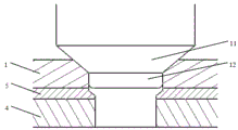
FIG. 1 is a view of the structure of the flap;
FIG. 2 is a schematic view of a hole making configuration of the present invention;
FIG. 3 is a schematic view of the dimple state.
Wherein: 1-opening cover, 3-waterproof rubber cushion, 4-skeleton structure, 5-process gasket, 6-drill bit, 7-drill bit and first-level reamer transition section, 8-first-level reamer section, 9-second-level reamer transition section, 10-second-level reamer section, 11-counter boring drill and 12-guide pin.
Detailed Description
Example 1:
an integrated hole making method of a quick-release opening cover is characterized in that a process gasket is arranged between an opening cover 1 and a framework structure 4, and a cutter outlet surface of an upper-layer opening cover 1 is attached to the process gasket so as to ensure that burrs and layering are not generated during hole making; simultaneously, holes are formed in the covering cap 1 and the framework structure 4, and in the hole forming process, holes with different hole diameters in the upper covering cap 1 and the lower framework structure 4 are formed by adopting an oversize depth limiter.
As shown in fig. 1, in the actual use process, a waterproof rubber mat 3 is arranged between the flap 1 and the skeleton structure 4. For avoiding appearing the wrong hole phenomenon of flap 1, 4 disalignments in aperture of skeleton texture, improve flap 1 mounting surface quality, need guarantee that flap 1 keeps unanimous with the actual installation state at assembly hole making state with skeleton texture 4's relative position, consequently is provided with the technology gasket between flap 1 and skeleton texture 4 to waterproof pad when the simulation installation. The invention realizes the purpose of compensating the manufacturing tolerance (4%) of the thickness of the opening cover 1 on one hand and the length of the tool diameter size transition region with inconsistent structural bore diameter of the opening cover 1 on the other hand through the thickness of the process gasket.
Example 2:
the embodiment is optimized on the basis of embodiment 1, and mainly comprises the following steps:
step S1: drilling and reaming integrated cutters and matching depth limiters to sequentially drill holes in the opening cover 1, the technical gaskets and the framework structure 4; the size of the depth limiter is equal to the sum of the upper limit of the thickness of the cover 1 and the pit depth of the size of the standard part;
step S2: a dimple drill 11 with a guide pin 12 is adopted to perform dimple boring by matching with a depth limiter, and a dimple with the size of a standard part is reamed on the opening cover 1; the diameter of the guide pin 12 is equal to the lower limit of the aperture of the flap 1, the length of the guide pin 12 is equal to the difference between the lower limit of the thickness of the flap 1 and the depth of the dimple, and the size of the depth limiter is equal to the dimple depth of the standard size.
The invention effectively avoids the phenomenon of hole dislocation caused by different diameters of the opening cover 1 and the framework structure 4 through the arrangement of the process gasket, improves the hole forming identity through a method of simultaneously forming holes on the opening cover 1 and the framework structure 4, reduces dislocation and errors among the diameters of the holes, and improves the hole forming efficiency and quality.
Other parts of this embodiment are the same as embodiment 1, and thus are not described again.
Example 3:
an integrated hole making method of a quick-release cover cap mainly comprises the following steps:
(1) measuring and calculating the thickness of the rubber cushion mounting machine; selecting a process gasket with stable thickness and matched with the thickness of the rubber pad binding machine;
a gasket is added between the opening cover 1 and the framework structure 4; fixing the opening cover 1, the process gasket and the framework structure 4 by using a piercing clip or other process connecting pieces;
(2) drilling and reaming integrated cutters are matched with depth limiters to perform hole making, and the cutters are used for making holes in sequence: a fixed opening cover 1, a technical gasket and a framework structure 4;
the depth stop is set at a size = upper thickness limit of the flap 1 + socket depth corresponding to the size of the standard.
(3) A dimple drill 11 with a guide pin 12 is used to perform dimple boring in cooperation with a depth stop, and a dimple corresponding to the size of a standard component is countersunk in the flap 1.
depth stop set size = socket depth corresponding to standard size.
As shown in fig. 2, the cutter comprises a drill bit 6, a drill bit and first reamer transition section 7, a first reamer section 8, a second reamer transition section 9 and a second reamer section 10. The depth limiter with the oversize is used, and holes with different apertures can be manufactured for the upper layer opening cover 1 and the lower layer framework structure 4 simultaneously in the hole manufacturing process. And the cutter can not only completely penetrate through the upper layer opening cover 1 of the hole-making lamination, but also does not damage the structure of the lower layer of the hole-making lamination, and a transition region from the aperture of the upper layer opening cover 1 of the cutter to the aperture of the structure is generated in the process gasket.
As shown in fig. 1, in the actual use process, a waterproof rubber mat 3 is arranged between the flap 1 and the skeleton structure 4. For avoiding appearing the wrong hole phenomenon of flap 1, 4 disalignments in aperture of skeleton texture, improve flap 1 mounting surface quality, need guarantee that flap 1 keeps unanimous with the actual installation state at assembly hole making state with skeleton texture 4's relative position, consequently is provided with the technology gasket between flap 1 and skeleton texture 4 to waterproof pad when the simulation installation. The invention realizes the purpose of compensating the manufacturing tolerance (4%) of the thickness of the opening cover 1 on one hand and the length of the tool diameter size transition region with inconsistent structural bore diameter of the opening cover 1 on the other hand through the thickness of the process gasket.
The invention effectively avoids the phenomenon of hole dislocation caused by different diameters of the opening cover 1 and the framework structure 4 through the arrangement of the process gasket, improves the hole forming identity through a method of simultaneously forming holes on the opening cover 1 and the framework structure 4, reduces dislocation and errors among the diameters of the holes, and improves the hole forming efficiency and quality.
The above description is only a preferred embodiment of the present invention, and is not intended to limit the present invention in any way, and all simple modifications and equivalent variations of the above embodiments according to the technical spirit of the present invention are included in the scope of the present invention.
Claims (6)
1. An integrated hole making method of a quick-release opening cover is characterized in that a process gasket is arranged between the opening cover and a framework structure, and a cutter outlet surface of an upper layer opening cover is attached to the process gasket so as to ensure that burrs and layering are not generated during hole making; simultaneously, holes are formed in the covering cap and the framework structure, and in the hole forming process, holes with different hole diameters in the upper covering cap and the lower framework structure are simultaneously formed by adopting an oversize depth limiter.
2. The integrated hole making method of the quick-release flap, as recited in claim 1, is characterized by mainly comprising the following steps:
step S1: drilling and reaming integrated cutters and matching depth limiters to sequentially drill holes in the opening covers, the process gaskets and the framework structures;
step S2: and (3) reaming a socket drill with a guide pin and matching with a depth limiter to perform reaming, and reaming a socket with the size of a standard part on the opening cover.
3. The method of claim 2, wherein the depth stop is sized to equal the sum of the upper thickness limit of the flap and the socket depth of a standard size.
4. The method of claim 3, wherein the guide pin diameter is equal to the lower aperture limit of the flap, the guide pin length is equal to the difference between the lower thickness limit of the flap and the depth of the countersink, and the depth stop is equal to the depth of the standard size.
5. The integrated hole making method of the quick-release opening cover as claimed in any one of claims 1 to 4, wherein the opening cover, the technical gasket and the skeleton structure are fixed by a connecting piece.
6. The method for integrally forming the hole of the quick release opening cover as claimed in claim 5, wherein the process gasket and the waterproof rubber mat have the same structure, and the process gasket and the waterproof rubber mat have the same thickness.
Priority Applications (1)
| Application Number | Priority Date | Filing Date | Title |
|---|---|---|---|
| CN202010414082.XA CN111673544A (en) | 2020-05-15 | 2020-05-15 | Integrated hole making method for quick-release opening cover |
Applications Claiming Priority (1)
| Application Number | Priority Date | Filing Date | Title |
|---|---|---|---|
| CN202010414082.XA CN111673544A (en) | 2020-05-15 | 2020-05-15 | Integrated hole making method for quick-release opening cover |
Publications (1)
| Publication Number | Publication Date |
|---|---|
| CN111673544A true CN111673544A (en) | 2020-09-18 |
Family
ID=72434060
Family Applications (1)
| Application Number | Title | Priority Date | Filing Date |
|---|---|---|---|
| CN202010414082.XA Pending CN111673544A (en) | 2020-05-15 | 2020-05-15 | Integrated hole making method for quick-release opening cover |
Country Status (1)
| Country | Link |
|---|---|
| CN (1) | CN111673544A (en) |
Citations (9)
| Publication number | Priority date | Publication date | Assignee | Title |
|---|---|---|---|---|
| SU420428A1 (en) * | 1969-09-30 | 1974-03-25 | А. С. Давыдов, В. Н. Семенов , А. Б. Витлин | DEVICE FOR CUTTING OF CURRENT CONDUCTIVE PARTS BY MELTING |
| CN1045055A (en) * | 1989-02-27 | 1990-09-05 | 阿图尔-费希尔股份公司费希尔厂 | drill bit |
| CN2649236Y (en) * | 2003-08-26 | 2004-10-20 | 陈军 | Motorcycle drum brake front cover worm hole composite drilling bit |
| CN2656056Y (en) * | 2003-11-24 | 2004-11-17 | 江苏精佳制动器集团有限公司 | Combined cutter |
| JP5597853B2 (en) * | 2010-09-28 | 2014-10-01 | 国立大学法人 千葉大学 | Through-hole electrode forming method and electronic component |
| CN104551128A (en) * | 2013-10-29 | 2015-04-29 | 常州市海力工具有限公司 | Three-blade drilling reamer |
| CN207971727U (en) * | 2018-03-30 | 2018-10-16 | 江苏金洋机械有限公司 | A kind of bore hole positioning tool of train bogie drawing pull bar |
| CN109227740A (en) * | 2018-09-05 | 2019-01-18 | 大连理工大学 | A kind of ion propeller carbon grid component method for drilling |
| CN209263818U (en) * | 2018-12-03 | 2019-08-16 | 江西洪都航空工业集团有限责任公司 | A kind of counter boring quality check tool |
-
2020
- 2020-05-15 CN CN202010414082.XA patent/CN111673544A/en active Pending
Patent Citations (9)
| Publication number | Priority date | Publication date | Assignee | Title |
|---|---|---|---|---|
| SU420428A1 (en) * | 1969-09-30 | 1974-03-25 | А. С. Давыдов, В. Н. Семенов , А. Б. Витлин | DEVICE FOR CUTTING OF CURRENT CONDUCTIVE PARTS BY MELTING |
| CN1045055A (en) * | 1989-02-27 | 1990-09-05 | 阿图尔-费希尔股份公司费希尔厂 | drill bit |
| CN2649236Y (en) * | 2003-08-26 | 2004-10-20 | 陈军 | Motorcycle drum brake front cover worm hole composite drilling bit |
| CN2656056Y (en) * | 2003-11-24 | 2004-11-17 | 江苏精佳制动器集团有限公司 | Combined cutter |
| JP5597853B2 (en) * | 2010-09-28 | 2014-10-01 | 国立大学法人 千葉大学 | Through-hole electrode forming method and electronic component |
| CN104551128A (en) * | 2013-10-29 | 2015-04-29 | 常州市海力工具有限公司 | Three-blade drilling reamer |
| CN207971727U (en) * | 2018-03-30 | 2018-10-16 | 江苏金洋机械有限公司 | A kind of bore hole positioning tool of train bogie drawing pull bar |
| CN109227740A (en) * | 2018-09-05 | 2019-01-18 | 大连理工大学 | A kind of ion propeller carbon grid component method for drilling |
| CN209263818U (en) * | 2018-12-03 | 2019-08-16 | 江西洪都航空工业集团有限责任公司 | A kind of counter boring quality check tool |
Non-Patent Citations (2)
| Title |
|---|
| 梁炳文: "《机械加工工艺图集 第3集》", 31 August 1993, 北京航空航天大学出版社 * |
| 许允: "《钳工操作实用技能全图解》", 30 June 2014, 河南科学技术出版社 * |
Similar Documents
| Publication | Publication Date | Title |
|---|---|---|
| CN201410616Y (en) | Perpendicular lining press fitting device | |
| CN102069395B (en) | Numerical control machining clamping method for aircraft wing beam parts | |
| CN107717343B (en) | Method for processing small-diameter precise blind hole | |
| CN111673544A (en) | Integrated hole making method for quick-release opening cover | |
| CN106226393B (en) | layered damage repairing method for laminated composite material structure | |
| CN102672240A (en) | Drilling jig for combination machining of cylinder body of diesel engine and flywheel shell | |
| CN202028806U (en) | Drill jig for decomposing raised head solid rivet | |
| CN106041185B (en) | The face milling cutters connector of valve upper cover processing line | |
| CN211477553U (en) | Vibration test device of aero-engine blisk | |
| CN201223962Y (en) | Step chip dividing groove deep hole drill | |
| CN107414438B (en) | Tool and method for on-site replacement of manual cover plate fixing screw of main gear box of engine | |
| CN201361733Y (en) | Vertical chambering sleeve | |
| CN219234050U (en) | Cabin door cutting and drilling auxiliary tool | |
| CN206732205U (en) | A kind of Combined type drill jig | |
| CN112935349A (en) | Method for machining accurate lead hole on skin of training machine | |
| CN218135180U (en) | Trepanning drill with replaceable cutter head | |
| CN214945558U (en) | Be applied to lock pin hole structure of back timber shrouding | |
| CN209986246U (en) | Cutter for hub machining | |
| CN209477856U (en) | A kind of jig boring water hole suitable for hub mold mold core | |
| CN208528169U (en) | A kind of cutting ball special-purpose milling cutter | |
| CN219074409U (en) | Repairing cutter for bearing seat of reduction gearbox of pumping unit | |
| CN215847999U (en) | Hidden hole leading tool | |
| CN110682058A (en) | Hole making method for large-curvature position of super-thick honeycomb sandwich structure | |
| CN104259846B (en) | A kind of nothing constraint assembly method of plug-in type binding bearing | |
| CN219292778U (en) | Diamond nickel-based blade |
Legal Events
| Date | Code | Title | Description |
|---|---|---|---|
| PB01 | Publication | ||
| PB01 | Publication | ||
| SE01 | Entry into force of request for substantive examination | ||
| SE01 | Entry into force of request for substantive examination | ||
| RJ01 | Rejection of invention patent application after publication |
Application publication date: 20200918 |
|
| RJ01 | Rejection of invention patent application after publication |