CN111672257A - Dust type mixed waste gas environmental protection treatment facility - Google Patents
Dust type mixed waste gas environmental protection treatment facility Download PDFInfo
- Publication number
- CN111672257A CN111672257A CN202010622871.2A CN202010622871A CN111672257A CN 111672257 A CN111672257 A CN 111672257A CN 202010622871 A CN202010622871 A CN 202010622871A CN 111672257 A CN111672257 A CN 111672257A
- Authority
- CN
- China
- Prior art keywords
- barrel
- waste gas
- dust
- rotating rod
- purification
- Prior art date
- Legal status (The legal status is an assumption and is not a legal conclusion. Google has not performed a legal analysis and makes no representation as to the accuracy of the status listed.)
- Granted
Links
Images


Classifications
-
- B—PERFORMING OPERATIONS; TRANSPORTING
- B01—PHYSICAL OR CHEMICAL PROCESSES OR APPARATUS IN GENERAL
- B01D—SEPARATION
- B01D50/00—Combinations of methods or devices for separating particles from gases or vapours
- B01D50/60—Combinations of devices covered by groups B01D46/00 and B01D47/00
-
- B—PERFORMING OPERATIONS; TRANSPORTING
- B01—PHYSICAL OR CHEMICAL PROCESSES OR APPARATUS IN GENERAL
- B01D—SEPARATION
- B01D53/00—Separation of gases or vapours; Recovering vapours of volatile solvents from gases; Chemical or biological purification of waste gases, e.g. engine exhaust gases, smoke, fumes, flue gases, aerosols
- B01D53/02—Separation of gases or vapours; Recovering vapours of volatile solvents from gases; Chemical or biological purification of waste gases, e.g. engine exhaust gases, smoke, fumes, flue gases, aerosols by adsorption, e.g. preparative gas chromatography
- B01D53/04—Separation of gases or vapours; Recovering vapours of volatile solvents from gases; Chemical or biological purification of waste gases, e.g. engine exhaust gases, smoke, fumes, flue gases, aerosols by adsorption, e.g. preparative gas chromatography with stationary adsorbents
-
- B—PERFORMING OPERATIONS; TRANSPORTING
- B01—PHYSICAL OR CHEMICAL PROCESSES OR APPARATUS IN GENERAL
- B01D—SEPARATION
- B01D2253/00—Adsorbents used in seperation treatment of gases and vapours
- B01D2253/10—Inorganic adsorbents
- B01D2253/102—Carbon
Landscapes
- Chemical & Material Sciences (AREA)
- Chemical Kinetics & Catalysis (AREA)
- Engineering & Computer Science (AREA)
- Analytical Chemistry (AREA)
- General Chemical & Material Sciences (AREA)
- Oil, Petroleum & Natural Gas (AREA)
- Water Treatment By Sorption (AREA)
Abstract
The invention relates to the field of waste gas treatment, in particular to dust mixed waste gas environment-friendly treatment equipment which comprises a mixing barrel for mixing and stirring dust, a material outlet box, a purification barrel for entering dust and waste gas, a primary filtering mechanism for filtering the dust and the waste gas, a secondary filtering mechanism, an active carbon adsorption box, a stirring assembly for filtering the dust and the waste gas and removing dust in the purification barrel, and a plurality of atomizing nozzles for mixing the dust and the waste gas with a purification solution, wherein the material outlet box is arranged below the mixing barrel, the purification barrel is arranged beside the mixing barrel through a four-foot stand, the lower part of the purification barrel is also provided with a water purification barrel for purifying water stains generated after the purification solution and the dust and the waste gas are mixed, and the inner center of the mixing barrel is provided with a first rotating rod along the length direction of the mixing barrel, so that the problems of incomplete purification of the dust and waste gas treatment and shortened service life of the equipment are solved, the purification effect of dust and waste gas is improved, and the environment is protected.
Description
Technical Field
The invention relates to the field of waste gas treatment, in particular to environment-friendly treatment equipment for dust mixed waste gas.
Background
The smoke generated in industrial production process contains many harmful substances and has special properties. The typical industry of smoke generation is in the refining industry. The smoke and dust waste gas has high smoke temperature, large dust content and large fluctuation range, some smoke has high humidity and contains corrosive gas and harmful gas, the dust waste gas can not only pollute the environment, but also can cause great harm to the body after people inhale, the existing dust waste gas is generally treated by a cyclone dust collector in a centrifugal mode, but some tiny dust is difficult to treat, and the dust centrifuged by the dust collector is likely to encounter wind in the collecting hopper, so that secondary pollution is easily caused.
Waste gas treatment equipment mainly refers to the application different process technology, through retrieving or getting rid of, reduce the harmful component who discharges tail gas, reaches the environmental protection equipment of environmental protection, air-purifying, lets our environment not receive the pollution, and the waste gas of dust class is generally unified through exhaust treatment device and is collected, then unified the processing, the very big environmental pollution that causes that has reduced dust waste gas, nevertheless current dust waste gas treatment device still has some weak points in the in-process that uses: when the existing dust and waste gas treatment device is used, more dust and dirt can be attached to the inner wall, and the existing dust and waste gas treatment device is not provided with a device convenient for workers to clean the inner wall, so that the inner wall can be corroded by the dust and the dirt, the use of the dust and waste gas treatment device is influenced, and the service life of the inner wall can be shortened.
To the mixed exhaust-gas treatment of dust class, need carry out multistage filtration to waste gas, non-staining environment when guaranteeing waste gas discharge to during exhaust-gas treatment, still need clear up in the treatment facility, in order to avoid the dust to be attached to the inside damage machine of equipment for a long time, consequently, need design one kind can be effectual to purifying waste gas, and guarantee that exhaust-gas treatment equipment is not fragile.
Disclosure of Invention
In order to solve the technical problem, the dust type mixed waste gas environment-friendly treatment equipment is provided, and the technical scheme solves the problems that the dust type waste gas is not completely purified and the service life of the equipment is shortened.
In order to achieve the above purposes, the technical scheme adopted by the invention is as follows: an environment-friendly treatment device for dust mixed waste gas comprises a mixing barrel for mixing and stirring dust, a material outlet box, a purification barrel for dust waste gas, a primary filtering mechanism for filtering dust waste gas, a secondary filtering mechanism, an active carbon adsorption box, a stirring assembly for filtering dust waste gas and removing dust in the purification barrel, and a plurality of atomization nozzles for mixing dust waste gas and purification liquid, wherein the mixing barrel is arranged at the top of a bracket in a horizontal state, the material outlet box is arranged below the mixing barrel, the purification barrel is arranged beside the mixing barrel through a four-foot stand, a water purification barrel for purifying water stains generated after the purification liquid and the dust waste gas are mixed is also arranged below the purification barrel, the primary filtering mechanism and the secondary filtering mechanism are respectively arranged in the purification barrel from bottom to top in sequence, and the active carbon adsorption box is arranged above the secondary filtering mechanism, and the active carbon adsorption case is located the purification bucket, and a plurality of atomizer all sets up on the purification bucket, and the stirring subassembly sets up in the inside of purification bucket, and the inside center of blending bucket is equipped with a first bull stick along the length direction of blending bucket, and the one end of blending bucket is the opening form, and the open end of blending bucket still is equipped with the bung of the first bull stick of dismouting of being convenient for.
As a preferred scheme of the environment-friendly treatment equipment for the dust mixed waste gas, the top of a mixing barrel is provided with a feeding port for feeding dust, the bottom of the mixing barrel is provided with a discharging port for discharging the dust, the bottom of a bracket is provided with a strip-shaped block, the bottom of a discharging box is clamped on the strip-shaped block through a bayonet which is convenient to pull out, a handle is arranged on one side of the material outlet box, an air duct is arranged at one end of the mixing barrel facing the purifying barrel, one end of the first rotating rod penetrates through the barrel cover to extend outwards, the extending end of the first rotating rod is driven by a first rotating motor, and the output shaft of the first rotating motor is connected with the extending end of the first rotating rod through a first coupling, a plurality of mixing rods are arranged on the outer side of the first rotating rod at equal intervals along the length direction of the first rotating rod, and the outer sides of the plurality of mixing rods are also uniformly provided with three first scraping rods used for scraping the inner wall of the mixing barrel along the length direction of the first rotating rod.
As an optimal scheme of dust type mixed waste gas environmental protection treatment facility, the purification bucket includes a foundation bucket, a ladle body, a top bucket and a top cap, the foundation bucket is fixed to be set up in the top of four-foot rest, one-level filtering mechanism sets up in the top of foundation bucket, the ladle body sets up in one-level filtering mechanism's top, second grade filtering mechanism sets up in the top of ladle body, top bucket sets up in second grade filtering mechanism's top, the active carbon adsorption tank sets up in the inside of top bucket, the top cap sets up in the top of top bucket, the bottom of foundation bucket still is equipped with a funnel that is used for waste gas purification back outflow waste water to get into the water purification bucket.
As an optimal scheme of dust type mixed waste gas environmental protection treatment facility, the inboard bottom of end bucket is equipped with a reposition of redundant personnel pipeline through a mounting disc, the inside wall of end bucket evenly is equipped with four draw-in grooves along the circumferencial direction, the joint of the dismouting of being convenient for through a fixture block respectively all around of mounting disc is in every draw-in groove, the top of reposition of redundant personnel pipeline still is equipped with a plurality of and is used for dust waste gas to get into the siphunculus in the end bucket, and still be connected through a coupling between the bottom of reposition of redundant personnel pipeline and the air duct of mixing drum and be equipped with an inlet duct, a plurality of atomizer sets up respectively on the lateral wall of end bucket and ladle body, the head end of every atomizer all passes the lateral wall of end bucket and ladle body and inwards stretches out, and still be equipped with a stock solution bucket.
As an optimal selection scheme of dust class mixed waste gas environmental protection treatment facility, the water purification bucket sets up in the below of funnel through a base, the top of water purification bucket still is equipped with a intercommunication mouth with funnel bottom intercommunication, the inside of water purification bucket still is equipped with a second bull stick, the second bull stick sets up along the axial lead direction of water purification bucket, the one end of second bull stick is passed the water purification bucket and is outwards stretched out, and the end that stretches out of second bull stick still is through a second rotating electrical machines drive, still be connected through a second coupling between the output of second rotating electrical machines and the end that stretches out of second bull stick, the outside of second bull stick still equidistant a plurality of water purification pole that is equipped with along the length direction of second bull stick, still be equipped with a filling tube that adds clean water liquid on the lateral wall of water purification bucket, the lateral wall bottom of water purification bucket still is equipped with a liquid outlet.
As an optimal scheme of dust type mixed waste gas environmental protection treatment facility, the structure homogeneous phase of one-level filtering mechanism and second grade filtering mechanism, one-level filtering mechanism and second grade filtering mechanism all include a U-shaped groove that is used for the installation, the top of end bucket and the top of ladle body still all are equipped with the round circular groove, the bottom in every U-shaped groove all is through a ring joint in corresponding circular inslot, the outside of every circular groove still all is fixed with corresponding ring through a plurality of fitting pin, the U-shaped inslot of one-level filtering mechanism and second grade filtering mechanism still respectively the joint be equipped with a first filter screen and a second filter screen, and the outside of first filter screen and second filter screen still all is equipped with the taking out of being convenient for taking out.
As an optimal scheme of dust type mixed waste gas environmental protection treatment facility, the top bucket, the top cap, equal corresponding by the bolt fastening between ladle body and the end bucket, the inside of top bucket is still vertical upwards evenly to be equipped with four stands along the circumferencial direction of top bucket, the activated carbon adsorption case is cylindricly, and on four stands were located to activated carbon adsorption case plug bush, the bottom of activated carbon adsorption case was located the inboard bottom of top bucket, still be equipped with the slot that a plurality of symmetry set up on the activated carbon adsorption case, still all link up the rectangle mouth that is equipped with a dust waste gas of being convenient for upwards circulate between per two slots, it is equipped with an activated carbon adsorption plate that is used for absorbing waste gas impurity still all to link up in every slot.
As an optimal scheme of dust class mixed waste gas environmental protection treatment facility, top one side of top cap is equipped with one and is used for the exhaust blast pipe after dust exhaust purification, the stirring subassembly includes a third bull stick and a gear drive mechanism, the third bull stick is vertical state and sets up along the axial lead direction of purifying the bucket, the bottom of third bull stick can the pivoted set up in the bottom of end bucket, gear drive mechanism sets up in the top of top cap, the top of third bull stick still is through a third rotating electrical machines drive, the top of top cap is fixed in through a frame to the third rotating electrical machines, and still be connected through a third shaft coupler between the output shaft of third rotating electrical machines and the third bull stick, the outside of third bull stick is located the inside of end bucket and ladle body along the length direction of third bull stick and still equidistant a plurality of puddler is equipped with.
As an optimal scheme of dust type mixed waste gas environmental protection treatment facility, gear drive mechanism is by a driving gear, an inner circle gear and three driven gear are constituteed, the inner circle gear is the fixed top that sets up in the top cap of horizontal state, coaxial line between inner circle gear and the third bull stick, the fixed cover of driving gear is located on the third bull stick, three driven gear is along the circumferencial direction evenly distributed of driving gear, and the teeth of a cogwheel of three driven gear respectively with the teeth of a cogwheel of driving gear and inner circle gear between intermeshing, every driven gear still all overlaps and locates in a pivot, the top of three pivot is still connected through a set-square.
As an optimal scheme of the environment-friendly dust mixed waste gas treatment equipment, a sleeve rod is sleeved on the third rotating rod, three extension rods uniformly extend outwards from the top end of the sleeve rod along the circumferential direction, each extension rod is sleeved at the bottom of the corresponding rotating shaft respectively, and three second scraping rods used for scraping and rubbing the inner wall are uniformly arranged in the sleeve positioned in the barrel body and the bottom barrel.
Compared with the prior art, the invention has the beneficial effects that: when an operator treats waste gas after dust mixing, firstly, the operator puts the dust into a mixing barrel, a first rotating rod stirs various types of dust through rotation, then, the mixed dust can generate waste gas, the waste gas flows into a purifying barrel, the mixed dust falls into a discharging box, the operator can take out the dust conveniently, the waste gas entering the purifying barrel carries out waste gas impurity removal through a first-stage filtering mechanism and a second-stage filtering mechanism, the waste gas flows upwards in the purifying barrel, a plurality of atomizing nozzles spray purifying liquid in the purifying barrel in an atomizing mode, a stirring assembly fully mixes the purifying liquid and the dust and the waste gas, the waste gas is purified, water stains can flow down after mixing the waste gas and the purifying liquid, the water stains flow into the purifying barrel to be filtered, the dust and the dust are convenient to protect the environment, then, the waste gas upwards enters an activated carbon adsorption box, the active carbon adsorption box finally purifies the waste gas, and finally, the waste gas is completely purified and then is discharged outwards, so that the environment-friendly effect is achieved.
Drawings
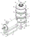
FIG. 1 is a schematic perspective view of the present invention;
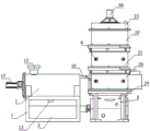
FIG. 2 is a front view of the present invention;
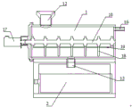
FIG. 3 is a cross-sectional view of a mixing barrel;
FIG. 4 is an exploded perspective view of the purification barrel;
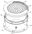
FIG. 5 is an exploded perspective view of the base barrel;
FIG. 6 is an exploded perspective view of the barrel;
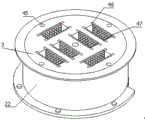
FIG. 7 is a perspective view of the top barrel;
FIG. 8 is a cross-sectional view of a clean water bucket;
FIG. 9 is a schematic perspective view of the stirring assembly;
fig. 10 is an exploded perspective view of the stirring assembly.
Description of reference numerals: the device comprises a mixing barrel 1, a discharging box 2, an activated carbon adsorption box 3, an atomizing nozzle 4, a primary filtering mechanism 5, a secondary filtering mechanism 6, a support 7, a four-foot stand 8, a purified water barrel 9, a first rotating rod 10, a barrel cover 11, a feeding port 12, a discharging port 13, a strip-shaped block 14, a handle 15, an air guide pipe 16, a first rotating motor 17, a mixing rod 18, a first scraping rod 19, a bottom barrel 20, a barrel body 21, a top barrel 22, a top cover 23, a funnel 24, a mounting disc 25, a shunt pipeline 26, a clamping groove 27, a clamping block 28, a through pipe 29, a pipe joint 30, an air inlet pipeline 31, a liquid storage barrel 32, a communication port 33, a second rotating rod 34, a second rotating motor 35, a purified water rod 36, a feeding pipe 37, a liquid outlet 38, a U-shaped groove 39, a circular groove 40, a circular ring 41, a first filter screen 42, a second filter screen 43, a drawing handle slot 44, a stand 45, a 46, an activated, A third rotating electric machine 50, a frame 51, a stirring rod 52, a driving gear 53, an inner ring gear 54, a driven gear 55, a triangle plate 56, a sleeve rod 57, an extension rod 58 and a second scraping rod 59.
Detailed Description
The following description is presented to disclose the invention so as to enable any person skilled in the art to practice the invention. The preferred embodiments in the following description are given by way of example only, and other obvious variations will occur to those skilled in the art.
Referring to fig. 1 to 10, an environment-friendly treatment device for dust mixed waste gas comprises a mixing barrel 1 for mixing and stirring dust, a discharging box 2, a purifying barrel for dust waste gas to enter, a primary filtering mechanism 5 for filtering dust waste gas, a secondary filtering mechanism 6, an activated carbon adsorption box 3, a stirring component for filtering dust waste gas and removing dust in the purifying barrel, and a plurality of atomizing nozzles 4 for mixing dust waste gas and purifying liquid, wherein the mixing barrel 1 is horizontally arranged at the top of a bracket 7, the discharging box 2 is arranged below the mixing barrel 1, the purifying barrel is arranged at the side of the mixing barrel 1 through a four-foot stand 8, a water purifying barrel 9 for purifying water stains generated after the purifying liquid and the dust waste gas are mixed is also arranged below the purifying barrel, the primary filtering mechanism 5 and the secondary filtering mechanism 6 are respectively arranged in the purifying barrel from bottom to top in sequence, activated carbon adsorption case 3 sets up in the top of second grade filter mechanism 6 to activated carbon adsorption case 3 is located the purifying barrel, and a plurality of atomizer 4 all sets up on the purifying barrel, and the stirring subassembly sets up in the inside of purifying barrel, and the inside center of blending bin 1 is equipped with a first bull stick 10 along blending bin 1's length direction, and the one end of blending bin 1 is the opening form, and the open end of blending bin 1 still is equipped with the bung 11 of the first bull stick 10 of the dismouting of being convenient for. When an operator treats waste gas after mixing dust, firstly, the operator puts the dust into the mixing barrel 1, the first rotating rod 10 stirs various types of dust through rotation, then, the mixed dust can generate waste gas, the waste gas flows into the purifying barrel, the mixed dust falls into the discharging box 2, the operator can take out the dust conveniently, the waste gas entering the purifying barrel can be purified through the first-stage filtering mechanism 5 and the second-stage filtering mechanism 6, the waste gas can flow upwards in the purifying barrel, a plurality of atomizing nozzles 4 spray purifying liquid in the purifying barrel in an atomizing mode, the stirring component fully mixes the purifying liquid with the dust and the waste gas, the waste gas is purified, the waste gas can flow water stain after mixing with the purifying liquid, the water stain flows into the purifying barrel 9 to be filtered, the environment is convenient to be protected, then, the waste gas upwards enters the active carbon adsorption box 3, the activated carbon adsorption tank 3 finally purifies the waste gas, and finally, the waste gas is completely purified and then discharged, so that the environment-friendly effect is achieved.
The top of the mixing barrel 1 is provided with a feeding port 12 for feeding dust, the bottom of the mixing barrel 1 is provided with a discharging port 13 for discharging the dust, the bottom of the bracket 7 is provided with a bar-shaped block 14, the bottom of the discharging box 2 is clamped on the bar-shaped block 14 through a bayonet which is convenient to pull out, a handle 15 is arranged on one side of the material outlet box 2, an air duct 16 is arranged at one end of the mixing barrel 1 facing the purifying barrel, one end of a first rotating rod 10 penetrates through the barrel cover 11 to extend outwards, the extending end of the first rotating rod 10 is driven by a first rotating motor 17, and the output shaft of the first rotating electrical machine 17 is connected with the extending end of the first rotating rod 10 through a first coupling, a plurality of mixing rods 18 are arranged on the outer side of the first rotating rod 10 at equal intervals along the length direction of the first rotating rod 10, and three first scraping rods 19 for scraping and rubbing the inner wall of the mixing barrel 1 are uniformly arranged on the outer sides of the plurality of mixing rods 18 along the length direction of the first rotating rod 10. When operating personnel handles the waste gas after the dust class mixes, at first, operating personnel drops into the tempering tank 1 with the dust through the input port 12 in, the first bull stick 10 of first rotating electrical machines 17 drive rotates, first bull stick 10 rotates and drives the multiclass dust of a plurality of tempering tank 18 in to tempering tank 1 and mix, when tempering tank 18 rotates, three first pole 19 of scraping is struck off the dust attachment of tempering tank 1 inner wall thereupon, prevent to damage the machine, the dust waste gas that produces after the dust stirring is accomplished passes through air duct 16 and flows out, the dust that stirs falls into ejection of compact box 2 through discharge gate 13 in, operating personnel conveniently takes out ejection of compact box 2 through handle 15.
The purification bucket includes a bottom bucket 20, a ladle body 21, a top bucket 22 and a top cap 23, bottom bucket 20 is fixed to be set up in the top of tetrapod frame 8, one-level filtering mechanism 5 sets up in the top of bottom bucket 20, ladle body 21 sets up in the top of one-level filtering mechanism 5, second grade filtering mechanism 6 sets up in the top of ladle body 21, top bucket 22 sets up in the top of second grade filtering mechanism 6, activated carbon adsorption tank 3 sets up in the inside of top bucket 22, top cap 23 sets up in the top of top bucket 22, bottom bucket 20's bottom still is equipped with a funnel 24 that is used for waste gas purification back outflow waste water to get into water purification bucket 9. After dust waste gas flowed into the purification bucket, waste gas carries out exhaust-gas treatment through one-level filtering mechanism 5, second grade filtering mechanism 6 and active carbon adsorption case 3, non-staining environment when guaranteeing waste gas discharge.
The inboard bottom of end bucket 20 is equipped with a reposition of redundant personnel pipeline 26 through a mounting disc 25, the inside wall of end bucket 20 evenly is equipped with four draw-in grooves 27 along the circumferencial direction, the joint that is convenient for the dismouting through a fixture block 28 respectively around mounting disc 25 is in every draw-in groove 27, the top of reposition of redundant personnel pipeline 26 still is equipped with a plurality of and is used for dust waste gas to get into siphunculus 29 in end bucket 20, and still be connected through a coupling 30 between the bottom of reposition of redundant personnel pipeline 26 and the air duct 16 of hybrid bucket 1 and be equipped with an inlet duct 31, a plurality of atomizer 4 sets up respectively on the lateral wall of end bucket 20 and ladle body 21, the head end of every atomizer 4 all passes the lateral wall of end bucket 20 and ladle body 21 and inwards stretches out, and still be equipped with a stock solution bucket 32 that is used for providing. When waste gas is discharged from air duct 16, because communicate through admission line 31 between inside diverging pipeline 26 of end bucket 20 and the air duct 16, consequently, waste gas enters into and discharges in end bucket 20 from a plurality of siphunculus 29 behind the diverging pipeline 26, the waste gas of being convenient for is discharged into the universality to and the purification of waste gas of being convenient for, then, a plurality of atomizer 4 on end bucket 20 turns into vaporific injection in end bucket 20 with the scavenging solution, waste gas and scavenging solution carry out preliminary mixing and obtain the purification.
The purified water bucket 9 is arranged below the funnel 24 through a base, the top of the purified water bucket 9 is further provided with a communicating opening 33 communicated with the bottom of the funnel 24, the inside of the purified water bucket 9 is further provided with a second rotating rod 34, the second rotating rod 34 is arranged along the axial lead direction of the purified water bucket 9, one end of the second rotating rod 34 penetrates through the purified water bucket 9 and extends outwards, the extending end of the second rotating rod 34 is further driven by a second rotating motor 35, the output end of the second rotating motor 35 is connected with the extending end of the second rotating rod 34 through a second coupler, the outer side of the second rotating rod 34 is further provided with a plurality of purified water rods 36 at equal intervals along the length direction of the second rotating rod 34, the side wall of the purified water bucket 9 is further provided with a feeding pipe 37 for adding purified water liquid, and the bottom of the purified water bucket 9 is further provided with a liquid outlet 38. After 4 spun purifying liquid of a plurality of atomizer and waste gas mix, owing to can produce water stain, consequently, water stain flows into water purification bucket 9 through intercommunication mouth 33 in, operating personnel passes through the filling tube 37 with the purifying liquid and adds in water purification bucket 9, and second rotating electrical machines 35 drives second bull stick 34 thereupon and rotates, and second bull stick 34 drives a plurality of purifying water pole 36 thereupon and carries out water purification treatment to waste water, and the water after the purification can not the polluted environment through liquid outlet 38 discharge.
The structure homogeneous phase of one-level filtering mechanism 5 and second grade filtering mechanism 6 is the same, one-level filtering mechanism 5 and second grade filtering mechanism 6 all include a U-shaped groove 39 that is used for the installation, the top of end bucket 20 and the top of ladle body 21 still all are equipped with round groove 40, the bottom of every U-shaped groove 39 all through a ring 41 joint in corresponding round groove 40, the outside of every round groove 40 still all is fixed with corresponding ring 41 through a plurality of locking bolt, still the joint is equipped with a first filter screen 42 and a second filter screen 43 in the U-shaped groove 39 of one-level filtering mechanism 5 and second grade filtering mechanism 6 respectively, and the outside of first filter screen 42 and second filter screen 43 still all is equipped with a take out handle 44 of being convenient for take out. Obtain preliminary edulcoration behind the first filter screen 42 that waste gas passes through one-level filter mechanism 5, in waste gas enters into ladle body 21 after that, a plurality of atomizer 4 on the ladle body 21 sprays the scavenging solution and mixes waste gas, and waste gas after further mixing carries out further edulcoration through second filter screen 43, because first filter screen 42 and second filter screen 43 all peg graft locate corresponding U-shaped inslot 39, consequently, operating personnel can conveniently clear up.
An exhaust pipe 48 for discharging the purified dust and waste gas is arranged on one side of the top cover 23, the stirring assembly comprises a third rotating rod 49 and a gear driving mechanism, the third rotating rod 49 is arranged in a vertical state along the axial lead direction of the purification barrel, the bottom end of the third rotating rod 49 can be rotatably arranged at the bottom of the bottom barrel 20, the gear driving mechanism is arranged at the top of the top cover 23, the top of the third rotating rod 49 is further driven by a third rotating motor 50, the third rotating motor 50 is fixed at the top of the top cover 23 through a rack 51, an output shaft of the third rotating motor 50 is connected with the third rotating rod 49 through a third coupler, and a plurality of stirring rods 52 are arranged in the bottom barrel 20 and the barrel body 21 along the length direction of the third rotating rod 49 and are arranged at equal intervals. When the in-process that the stirring assembly carried out intensive mixing between to waste gas and the purifying liquid, third rotating electrical machines 50 drive third bull stick 49 and rotate, and third bull stick 49 rotates and drives a plurality of puddler 52 along with it and rotates, and a plurality of puddler 52 carries out intensive mixing between to waste gas and the purifying liquid, guarantees waste gas purification's effect.
The gear driving mechanism is composed of a driving gear 53, an inner ring gear 54 and three driven gears 55, the inner ring gear 54 is horizontally and fixedly arranged at the top of the top cover 23, the inner ring gear 54 and the third rotating rod 49 are coaxial, the driving gear 53 is fixedly sleeved on the third rotating rod 49, the three driven gears 55 are uniformly distributed along the circumferential direction of the driving gear 53, the gear teeth of the three driven gears 55 are meshed with the gear teeth of the driving gear 53 and the inner ring gear 54 respectively, each driven gear 55 is further sleeved on a rotating shaft, and the tops of the three rotating shafts are further connected through a triangular plate 56. When the third rotating rod 49 rotates, the driving gear 53 rotates, and since the teeth of the three driven gears 55 are engaged with the driving gear 53 and the inner ring gear 54, respectively, the three driven gears 55 rotate along the circumferential direction of the driving gear 53, and the triangle 56 is connected to the three rotating shafts sleeved with the three driven gears 55, thereby facilitating the stability of the rotation of the three driven gears 55.
A sleeve rod 57 is sleeved on the third rotating rod 49, three extension rods 58 are further uniformly and outwardly extended from the top end of the sleeve rod 57 along the circumferential direction, each extension rod 58 is respectively sleeved at the bottom of a corresponding rotating shaft, and three second scraping rods 59 for scraping inner walls are further uniformly arranged in the sleeve positioned in the barrel body 21 and the bottom barrel 20. After three driven gear 55 rotated, because the loop bar 57 locates the bottom of corresponding pivot through every extension rod 58 cover, consequently, loop bar 57 rotates along third bull stick 49 opposite direction thereupon, and when third bull stick 49 rotated and mixes waste gas and purifying liquid, loop bar 57 rotated the drive simultaneously with three second in the end bucket 20 scrape pole 59 scrape the adnexed waste water on the inner wall and scrape off, make waste water downward flow, guaranteed the life-span of machine.
The working principle of the invention is as follows: the device/apparatus/method realizes the functions of the invention by the following steps, thereby solving the technical problems proposed by the invention:
firstly, when an operator treats waste gas after mixing dust, firstly, the operator puts the dust into the mixing barrel 1 through the input port 12, the first rotating motor 17 drives the first rotating rod 10 to rotate, the first rotating rod 10 rotates to drive the mixing rods 18 to mix and stir various types of dust in the mixing barrel 1, when the mixing rods 18 rotate, the three first scraping rods 19 scrape off dust attachments on the inner wall of the mixing barrel 1 along with the dust attachments to prevent damage to the machine, dust waste gas generated after dust stirring flows out through the air duct 16, the stirred dust falls into the discharging box 2 through the discharging port 13, the operator conveniently takes out the discharging box 2 through the handle 15, when the waste gas is discharged from the air duct 16, because the shunting pipeline 26 in the bottom barrel 20 is communicated with the air duct 16 through the air inlet pipeline 31, the waste gas enters the shunting pipeline 26 and then is discharged into the bottom barrel 20 through the plurality of through pipes 29, the device facilitates the universality of exhaust gas discharge and the purification of the exhaust gas.
Step two, after dust and waste gas flow into the bottom barrel 20, waste gas is treated through the first-stage filtering mechanism 5, the second-stage filtering mechanism 6 and the activated carbon adsorption tank 3, and no pollution to the environment is ensured when the waste gas is discharged, the plurality of atomizing nozzles 4 on the bottom barrel 20 convert the purifying liquid into mist to be sprayed into the bottom barrel 20, the waste gas and the purifying liquid are preliminarily mixed to be purified, preliminary impurity removal is obtained after the waste gas passes through the first filter screen 42 of the first-stage filtering mechanism 5, then the waste gas enters the barrel body 21, the plurality of atomizing nozzles 4 on the barrel body 21 spray the purifying liquid to mix the waste gas, the further mixed waste gas is further subjected to impurity removal through the second filter screen 43, as the first filter screen 42 and the second filter screen 43 are inserted into the corresponding U-shaped grooves 39, therefore, an operator can conveniently clean the waste gas, and after the purifying liquid sprayed by the plurality of atomizing nozzles 4 is mixed with the waste gas, because can produce water stain, consequently, water stain flows into water purification bucket 9 through intercommunication mouth 33 in, and operating personnel adds water purification bucket 9 with the water purification liquid through filling tube 37 in, and second rotating electrical machines 35 drives second bull stick 34 thereupon and rotates, and second bull stick 34 drives a plurality of water purification pole 36 thereupon and carries out water purification treatment to waste water, and the water after the purification can not the polluted environment through the discharge of liquid outlet 38.
Step three, in the process that the stirring assembly fully mixes the exhaust gas and the purifying liquid, the third rotating motor 50 drives the third rotating rod 49 to rotate, the third rotating rod 49 rotates to drive the stirring rods 52 to rotate, the stirring rods 52 fully mix the exhaust gas and the purifying liquid, the effect of purifying the exhaust gas is ensured, when the third rotating rod 49 rotates, the driving gear 53 rotates along with the third rotating rod, because the teeth of the three driven gears 55 are respectively meshed with the driving gear 53 and the inner ring gear 54, the three driven gears 55 rotate along with the circumferential direction of the driving gear 53, the triangular plate 56 is connected with the three rotating shafts sleeved with the three driven gears 55, the stability of the rotation of the three driven gears 55 is facilitated, and because the sleeve 57 is sleeved at the bottom of the corresponding rotating shaft through each extension rod 58, the sleeve 57 rotates along with the third rotating rod 49 in the opposite direction, when third bull stick 49 rotates and mixes waste gas and purifying liquid, the rotation of loop bar 57 drives simultaneously scrapes with three second in the end bucket 20 and scrapes the adnexed waste water on the inner wall with pole 59, makes the downward circulation of waste water, has guaranteed the life-span of machine.
Step four, after the waste gas flows upwards to enter the activated carbon adsorption tank 3, because the activated carbon adsorption tank 3 is internally clamped with a plurality of symmetrically arranged activated carbon adsorption plates 47, when the waste gas passes between every two activated carbon adsorption plates 47, the waste gas is finally purified, and the waste gas finally flows upwards to be discharged.
The foregoing shows and describes the general principles, essential features, and advantages of the invention. It will be understood by those skilled in the art that the present invention is not limited to the embodiments described above, which are merely illustrative of the principles of the invention, but that various changes and modifications may be made without departing from the spirit and scope of the invention, which fall within the scope of the invention as claimed. The scope of the invention is defined by the appended claims and equivalents thereof.
Claims (10)
1. The dust mixed waste gas environment-friendly treatment equipment is characterized by comprising a mixing barrel (1) for mixing and stirring dust, a discharge box (2), a purification barrel for entering dust and waste gas, a primary filtering mechanism (5) for filtering the dust and waste gas, a secondary filtering mechanism (6), an activated carbon adsorption box (3), a stirring assembly for filtering the dust and waste gas and removing dust in the purification barrel and a plurality of atomizing nozzles (4) for mixing the dust and waste gas with a purification solution, wherein the mixing barrel (1) is horizontally arranged at the top of a bracket (7), the discharge box (2) is arranged below the mixing barrel (1), the purification barrel is arranged at the side of the mixing barrel (1) through a four-foot stand (8), a water purification barrel (9) for purifying water stains generated after the purification solution and the dust and waste gas are mixed is also arranged below the purification barrel, one-level filtering mechanism (5) and second grade filtering mechanism (6) are respectively from down supreme setting gradually in the inside of purifying barrel, activated carbon adsorption case (3) set up in the top of second grade filtering mechanism (6), and activated carbon adsorption case (3) are located the purifying barrel, a plurality of atomizer (4) all set up on the purifying barrel, the stirring subassembly sets up in the inside of purifying barrel, the inside center of blending bin (1) is equipped with a first bull stick (10) along the length direction of blending bin (1), the one end of blending bin (1) is the opening form, the open end of blending bin (1) still is equipped with bung (11) of the first bull stick (10) of dismouting of being convenient for.
2. The environment-friendly dust mixed waste gas treatment equipment according to claim 1, wherein a feeding port (12) for feeding dust is arranged at the top of the mixing barrel (1), a discharging port (13) for discharging dust is arranged at the bottom of the mixing barrel (1), a bar-shaped block (14) is arranged at the bottom of the bracket (7), the bottom of the discharging box (2) is connected to the bar-shaped block (14) in a clamping manner through a bayonet so as to be conveniently pulled out, a handle (15) is further arranged at one side of the discharging box (2), an air duct (16) is further arranged at one end of the mixing barrel (1) facing the purification barrel, one end of the first rotating rod (10) penetrates through the barrel cover (11) to extend outwards, the extending end of the first rotating rod (10) is driven by a first rotating motor (17), and the output shaft of the first rotating motor (17) is connected with the extending end of the first rotating rod (10) through a first coupling, a plurality of mixing rods (18) are arranged on the outer side of the first rotating rod (10) at equal intervals along the length direction of the first rotating rod (10), and three first scraping rods (19) used for scraping the inner wall of the mixing barrel (1) are further uniformly arranged on the outer side of the mixing rods (18) along the length direction of the first rotating rod (10).
3. The environment-friendly dust mixed waste gas treatment equipment according to claim 2, wherein the purification barrel comprises a bottom barrel (20), a barrel body (21), a top barrel (22) and a top cover (23), the bottom barrel (20) is fixedly arranged at the top of the four-foot stand (8), the primary filtering mechanism (5) is arranged at the top of the bottom barrel (20), the barrel body (21) is arranged at the top of the primary filtering mechanism (5), the secondary filtering mechanism (6) is arranged at the top of the barrel body (21), the top barrel (22) is arranged at the top of the secondary filtering mechanism (6), the activated carbon adsorption tank (3) is arranged inside the top barrel (22), the top cover (23) is arranged at the top of the top barrel (22), and a funnel (24) for waste water flowing out after waste gas purification to enter the water purification barrel (9) is further arranged at the bottom of the bottom barrel (20).
4. The environment-friendly dust mixed waste gas treatment equipment as claimed in claim 3, wherein a distribution pipeline (26) is arranged at the bottom of the inner side of the bottom barrel (20) through a mounting plate (25), four clamping grooves (27) are uniformly arranged on the inner side wall of the bottom barrel (20) along the circumferential direction, the periphery of the mounting plate (25) is clamped in each clamping groove (27) through a clamping block (28) for facilitating disassembly and assembly, a plurality of through pipes (29) for dust and waste gas to enter the bottom barrel (20) are further arranged at the top of the distribution pipeline (26), an air inlet pipeline (31) is further connected between the bottom of the distribution pipeline (26) and the air duct (16) of the mixing barrel (1) through a pipe joint (30), a plurality of atomizing nozzles (4) are respectively arranged on the outer side walls of the bottom barrel (20) and the barrel body (21), and the head end of each atomizing nozzle (4) penetrates through the bottom barrel (20) and the outer side wall of the barrel body (21) to extend inwards, and a liquid storage barrel (32) for providing purified liquid is also arranged on the outer side wall of the bottom barrel (20).
5. The environment-friendly dust mixed waste gas treatment equipment according to claim 3, wherein the water purification barrel (9) is arranged below the funnel (24) through a base, the top of the water purification barrel (9) is further provided with a communication port (33) communicated with the bottom of the funnel (24), the water purification barrel (9) is further internally provided with a second rotating rod (34), the second rotating rod (34) is arranged along the axial lead direction of the water purification barrel (9), one end of the second rotating rod (34) penetrates through the water purification barrel (9) to extend outwards, the extending end of the second rotating rod (34) is further driven by a second rotating motor (35), the output end of the second rotating motor (35) is further connected with the extending end of the second rotating rod (34) through a second coupler, the outer side of the second rotating rod (34) is further provided with a plurality of water purification rods (36) at equal intervals along the length direction of the second rotating rod (34), the side wall of the purified water barrel (9) is also provided with a feed pipe (37) for adding purified water liquid, and the bottom of the side wall of the purified water barrel (9) is also provided with a liquid outlet (38).
6. The environment-friendly dust mixed waste gas treatment equipment according to claim 3, wherein the primary filtering mechanism (5) and the secondary filtering mechanism (6) have the same structure, the primary filtering mechanism (5) and the secondary filtering mechanism (6) both comprise a U-shaped groove (39) for installation, the top of the bottom barrel (20) and the top of the barrel body (21) are provided with a circle of circular grooves (40), the bottom of each U-shaped groove (39) is clamped in the corresponding circular groove (40) through a circular ring (41), the outer side of each circular groove (40) is fixed with the corresponding circular ring (41) through a plurality of locking bolts, the U-shaped grooves (39) of the primary filtering mechanism (5) and the secondary filtering mechanism (6) are respectively clamped with a first filter screen (42) and a second filter screen (43), and the outward side of the first filter screen (42) and the second filter screen (43) is provided with a drawing handle (44) for drawing conveniently .
7. The environment-friendly dust mixed waste gas treatment equipment according to claim 6, wherein the top barrel (22), the top cover (23), the barrel body (21) and the bottom barrel (20) are correspondingly fixed by bolts, four upright columns (45) are vertically and uniformly arranged in the top barrel (22) along the circumferential direction of the top barrel (22), the activated carbon adsorption tank (3) is cylindrical, and on four stand (45) were located to activated carbon adsorption case (3) grafting cover, the bottom of activated carbon adsorption case (3) was located the inboard bottom of top bucket (22), still is equipped with slot (46) that a plurality of symmetry set up on activated carbon adsorption case (3), still all link up between per two slot (46) and be equipped with a rectangle mouth that is convenient for dust waste gas to flow upwards, still all the joint is equipped with one activated carbon adsorption board (47) that are used for absorbing waste gas impurity in every slot (46).
8. The environment-friendly dust mixed waste gas treatment equipment as claimed in claim 7, wherein one side of the top cover (23) is provided with an exhaust pipe (48) for discharging the dust and waste gas after purification, the stirring assembly comprises a third rotating rod (49) and a gear driving mechanism, the third rotating rod (49) is arranged in a vertical state along the axial lead direction of the purification barrel, the bottom end of the third rotating rod (49) is rotatably arranged at the bottom of the bottom barrel (20), the gear driving mechanism is arranged at the top of the top cover (23), the top of the third rotating rod (49) is further driven by a third rotating motor (50), the third rotating motor (50) is fixed at the top of the top cover (23) through a frame (51), and an output shaft of the third rotating motor (50) is connected with the third rotating rod (49) through a third coupling, the outer side of the third rotating rod (49) is positioned inside the bottom barrel (20) and the barrel body (21) along the length direction of the third rotating rod (49) and is also provided with a plurality of stirring rods (52) at equal intervals.
9. The environment-friendly dust mixed waste gas treatment equipment as claimed in claim 8, wherein the gear driving mechanism is composed of a driving gear (53), an inner ring gear (54) and three driven gears (55), the inner ring gear (54) is fixedly arranged at the top of the top cover (23) in a horizontal state, the inner ring gear (54) and the third rotating rod (49) share the same axis, the driving gear (53) is fixedly sleeved on the third rotating rod (49), the three driven gears (55) are uniformly distributed along the circumferential direction of the driving gear (53), the gear teeth of the three driven gears (55) are respectively meshed with the gear teeth of the driving gear (53) and the gear teeth of the inner ring gear (54), each driven gear (55) is further sleeved on a rotating shaft, and the tops of the three rotating shafts are further connected through a triangular plate (56).
10. The environment-friendly dust mixed waste gas treatment equipment as claimed in claim 9, wherein a loop bar (57) is sleeved on the third rotating bar (49), the top end of the loop bar (57) is further uniformly extended outwards along the circumferential direction to form three extension bars (58), each extension bar (58) is respectively sleeved at the bottom of the corresponding rotating shaft, and three second scraping bars (59) for scraping the inner wall of the sleeve are further uniformly arranged inside the barrel body (21) and the bottom barrel (20).
Priority Applications (1)
| Application Number | Priority Date | Filing Date | Title |
|---|---|---|---|
| CN202010622871.2A CN111672257B (en) | 2020-07-01 | 2020-07-01 | Dust type mixed waste gas environmental protection treatment facility |
Applications Claiming Priority (1)
| Application Number | Priority Date | Filing Date | Title |
|---|---|---|---|
| CN202010622871.2A CN111672257B (en) | 2020-07-01 | 2020-07-01 | Dust type mixed waste gas environmental protection treatment facility |
Publications (2)
| Publication Number | Publication Date |
|---|---|
| CN111672257A true CN111672257A (en) | 2020-09-18 |
| CN111672257B CN111672257B (en) | 2021-11-16 |
Family
ID=72457021
Family Applications (1)
| Application Number | Title | Priority Date | Filing Date |
|---|---|---|---|
| CN202010622871.2A Active CN111672257B (en) | 2020-07-01 | 2020-07-01 | Dust type mixed waste gas environmental protection treatment facility |
Country Status (1)
| Country | Link |
|---|---|
| CN (1) | CN111672257B (en) |
Cited By (3)
| Publication number | Priority date | Publication date | Assignee | Title |
|---|---|---|---|---|
| CN112774420A (en) * | 2020-12-21 | 2021-05-11 | 王倩 | Industrial waste gas high concentration acid mist purifying tower |
| CN112774397A (en) * | 2021-01-26 | 2021-05-11 | 广州万为通达科技有限公司 | Waste gas treatment device of biological fermentation tank |
| CN113350963A (en) * | 2021-05-24 | 2021-09-07 | 哈尔滨商业大学 | Pharmacy is with having exhaust gas purification system's organic synthesizer |
Citations (8)
| Publication number | Priority date | Publication date | Assignee | Title |
|---|---|---|---|---|
| CN107715635A (en) * | 2017-11-13 | 2018-02-23 | 安徽万山红环保科技有限公司 | A kind of catalytic converter |
| US10053385B1 (en) * | 2018-04-23 | 2018-08-21 | Ziyu Zhu | Device for separating water from sludge |
| CN208553595U (en) * | 2018-07-17 | 2019-03-01 | 山东百特机械设备有限公司 | A kind of new multistage adsorption tower |
| CN208626992U (en) * | 2018-05-23 | 2019-03-22 | 黄涌炜 | A kind of exhaust gas purification and treatment device |
| CN209576144U (en) * | 2018-12-29 | 2019-11-05 | 银发环保股份有限公司 | A kind of waste gas purification apparatus |
| CN210229833U (en) * | 2019-06-18 | 2020-04-03 | 杭州聚邦建设有限公司 | Architectural coating mixing arrangement |
| CN210308524U (en) * | 2019-06-12 | 2020-04-14 | 沧州市鑫峰塑料有限公司 | Plastic film production and processing is with raw materials compounding device |
| CN210729713U (en) * | 2019-05-06 | 2020-06-12 | 丹阳市现代实业有限公司 | High performance water based paint sanding system |
-
2020
- 2020-07-01 CN CN202010622871.2A patent/CN111672257B/en active Active
Patent Citations (8)
| Publication number | Priority date | Publication date | Assignee | Title |
|---|---|---|---|---|
| CN107715635A (en) * | 2017-11-13 | 2018-02-23 | 安徽万山红环保科技有限公司 | A kind of catalytic converter |
| US10053385B1 (en) * | 2018-04-23 | 2018-08-21 | Ziyu Zhu | Device for separating water from sludge |
| CN208626992U (en) * | 2018-05-23 | 2019-03-22 | 黄涌炜 | A kind of exhaust gas purification and treatment device |
| CN208553595U (en) * | 2018-07-17 | 2019-03-01 | 山东百特机械设备有限公司 | A kind of new multistage adsorption tower |
| CN209576144U (en) * | 2018-12-29 | 2019-11-05 | 银发环保股份有限公司 | A kind of waste gas purification apparatus |
| CN210729713U (en) * | 2019-05-06 | 2020-06-12 | 丹阳市现代实业有限公司 | High performance water based paint sanding system |
| CN210308524U (en) * | 2019-06-12 | 2020-04-14 | 沧州市鑫峰塑料有限公司 | Plastic film production and processing is with raw materials compounding device |
| CN210229833U (en) * | 2019-06-18 | 2020-04-03 | 杭州聚邦建设有限公司 | Architectural coating mixing arrangement |
Cited By (3)
| Publication number | Priority date | Publication date | Assignee | Title |
|---|---|---|---|---|
| CN112774420A (en) * | 2020-12-21 | 2021-05-11 | 王倩 | Industrial waste gas high concentration acid mist purifying tower |
| CN112774397A (en) * | 2021-01-26 | 2021-05-11 | 广州万为通达科技有限公司 | Waste gas treatment device of biological fermentation tank |
| CN113350963A (en) * | 2021-05-24 | 2021-09-07 | 哈尔滨商业大学 | Pharmacy is with having exhaust gas purification system's organic synthesizer |
Also Published As
| Publication number | Publication date |
|---|---|
| CN111672257B (en) | 2021-11-16 |
Similar Documents
| Publication | Publication Date | Title |
|---|---|---|
| CN111672257B (en) | Dust type mixed waste gas environmental protection treatment facility | |
| CN210814637U (en) | Purification and discharge device for waste gas generated in production of high-precision injection molding machine | |
| CN214513124U (en) | Desulfurizing tower adds medicine filtration equipment | |
| CN109650619A (en) | A kind of centrifugal chemical engineering sewage recycling and reusing device | |
| CN115572001A (en) | Sewage treatment environmental protection machinery | |
| CN213141653U (en) | Coating circulating water treatment equipment | |
| CN212492765U (en) | Discharging and filtering device of stirring device | |
| CN211514200U (en) | Chemical particle stirrer dust collector | |
| CN111921314A (en) | Wet scrubbing type dust remover | |
| CN112320139A (en) | Laboratory garbage treatment device and use method thereof | |
| CN111928480B (en) | Pipeless hot blast stove | |
| CN212757995U (en) | Energy-concerving and environment-protective type waste gas treatment device for cement manufacture | |
| CN214261203U (en) | Graphite processing tail gas treatment facility that can circulate and spray | |
| CN116371171B (en) | VOCs mixed waste gas treatment device and treatment process thereof | |
| CN220802581U (en) | Exhaust treatment machine capable of uniformly spraying | |
| CN214389183U (en) | Feeding filter of used engine oil treatment stripping tower | |
| CN220646008U (en) | Wet dust removal fan for mine tunneling | |
| CN216092739U (en) | Effective waste gas treatment device for environmental protection equipment | |
| CN216918904U (en) | Coking wastewater ammonia nitrogen component removing equipment | |
| CN213610314U (en) | Dust collector is used in pitch production | |
| CN216093651U (en) | Reaction unit is used in rubber production convenient to separation slagging-off | |
| CN211587845U (en) | Stirring host computer belt cleaning device | |
| CN216997981U (en) | Circulating waste water photocatalysis treatment device | |
| CN217383848U (en) | Novel quench tower capable of reducing inner wall dust deposition problem of washing wastewater recycling | |
| CN220609334U (en) | Solid-liquid separation device convenient to use |
Legal Events
| Date | Code | Title | Description |
|---|---|---|---|
| PB01 | Publication | ||
| PB01 | Publication | ||
| SE01 | Entry into force of request for substantive examination | ||
| SE01 | Entry into force of request for substantive examination | ||
| TA01 | Transfer of patent application right |
Effective date of registration: 20211020 Address after: 223700 development avenue of Chuancheng national entrepreneurship Park, Siyang County, Suqian City, Jiangsu Province Applicant after: Suqian Qirui Environmental Protection Technology Co.,Ltd. Address before: 323007 No.27, Chikeng gaopan village, Laozhu she Town, Liandu District, Lishui City, Zhejiang Province Applicant before: Li Baiqing |
|
| TA01 | Transfer of patent application right | ||
| GR01 | Patent grant | ||
| GR01 | Patent grant |