CN111663757A - Door-type scaffold for building engineering - Google Patents
Door-type scaffold for building engineering Download PDFInfo
- Publication number
- CN111663757A CN111663757A CN202010597118.2A CN202010597118A CN111663757A CN 111663757 A CN111663757 A CN 111663757A CN 202010597118 A CN202010597118 A CN 202010597118A CN 111663757 A CN111663757 A CN 111663757A
- Authority
- CN
- China
- Prior art keywords
- wall
- fixedly connected
- type scaffold
- scaffold
- frame
- Prior art date
- Legal status (The legal status is an assumption and is not a legal conclusion. Google has not performed a legal analysis and makes no representation as to the accuracy of the status listed.)
- Pending
Links
- 238000010276 construction Methods 0.000 claims abstract description 26
- 230000006978 adaptation Effects 0.000 claims description 3
- 239000002184 metal Substances 0.000 claims description 3
- 230000000149 penetrating effect Effects 0.000 claims description 3
- 230000001681 protective effect Effects 0.000 claims description 3
- 238000000034 method Methods 0.000 description 13
- 238000003860 storage Methods 0.000 description 8
- 230000008569 process Effects 0.000 description 7
- 230000036541 health Effects 0.000 description 5
- 230000000694 effects Effects 0.000 description 4
- 230000007246 mechanism Effects 0.000 description 4
- 230000009471 action Effects 0.000 description 3
- 238000009435 building construction Methods 0.000 description 3
- 230000009194 climbing Effects 0.000 description 2
- 239000011435 rock Substances 0.000 description 2
- 206010016173 Fall Diseases 0.000 description 1
- 230000004075 alteration Effects 0.000 description 1
- 238000005452 bending Methods 0.000 description 1
- 230000009286 beneficial effect Effects 0.000 description 1
- 230000008859 change Effects 0.000 description 1
- 238000005034 decoration Methods 0.000 description 1
- 230000007547 defect Effects 0.000 description 1
- 238000013461 design Methods 0.000 description 1
- 238000003780 insertion Methods 0.000 description 1
- 230000037431 insertion Effects 0.000 description 1
- 238000012423 maintenance Methods 0.000 description 1
- 238000004519 manufacturing process Methods 0.000 description 1
- 238000012986 modification Methods 0.000 description 1
- 230000004048 modification Effects 0.000 description 1
- 238000003825 pressing Methods 0.000 description 1
- 238000006467 substitution reaction Methods 0.000 description 1
- 238000009941 weaving Methods 0.000 description 1
Images



Classifications
-
- E—FIXED CONSTRUCTIONS
- E04—BUILDING
- E04G—SCAFFOLDING; FORMS; SHUTTERING; BUILDING IMPLEMENTS OR AIDS, OR THEIR USE; HANDLING BUILDING MATERIALS ON THE SITE; REPAIRING, BREAKING-UP OR OTHER WORK ON EXISTING BUILDINGS
- E04G1/00—Scaffolds primarily resting on the ground
- E04G1/28—Scaffolds primarily resting on the ground designed to provide support only at a low height
- E04G1/30—Ladder scaffolds
-
- E—FIXED CONSTRUCTIONS
- E04—BUILDING
- E04G—SCAFFOLDING; FORMS; SHUTTERING; BUILDING IMPLEMENTS OR AIDS, OR THEIR USE; HANDLING BUILDING MATERIALS ON THE SITE; REPAIRING, BREAKING-UP OR OTHER WORK ON EXISTING BUILDINGS
- E04G5/00—Component parts or accessories for scaffolds
- E04G5/003—Devices for storing material on the scaffold
-
- E—FIXED CONSTRUCTIONS
- E04—BUILDING
- E04G—SCAFFOLDING; FORMS; SHUTTERING; BUILDING IMPLEMENTS OR AIDS, OR THEIR USE; HANDLING BUILDING MATERIALS ON THE SITE; REPAIRING, BREAKING-UP OR OTHER WORK ON EXISTING BUILDINGS
- E04G5/00—Component parts or accessories for scaffolds
- E04G5/08—Scaffold boards or planks
-
- E—FIXED CONSTRUCTIONS
- E04—BUILDING
- E04G—SCAFFOLDING; FORMS; SHUTTERING; BUILDING IMPLEMENTS OR AIDS, OR THEIR USE; HANDLING BUILDING MATERIALS ON THE SITE; REPAIRING, BREAKING-UP OR OTHER WORK ON EXISTING BUILDINGS
- E04G1/00—Scaffolds primarily resting on the ground
- E04G1/28—Scaffolds primarily resting on the ground designed to provide support only at a low height
- E04G1/30—Ladder scaffolds
- E04G2001/302—Ladder scaffolds with ladders supporting the platform
- E04G2001/305—The ladders being vertical and perpendicular to the platform
Landscapes
- Engineering & Computer Science (AREA)
- Architecture (AREA)
- Mechanical Engineering (AREA)
- Civil Engineering (AREA)
- Structural Engineering (AREA)
- Movable Scaffolding (AREA)
Abstract
The invention discloses a door type scaffold for constructional engineering, which comprises a door frame cross beam, wherein two ends of the bottom of the door frame cross beam are fixedly connected with support frames, a treading cross beam is fixedly connected between the support frames, one end of the bottom of the treading cross beam is fixedly connected with a treading device, when a user needs to stand on the scaffold for operation, the foot can be inserted into the treading device, the situation that the foot shakes with the body during body movement is avoided, the risk that an operator slips off the scaffold is reduced, slots are formed in two sides of one end, away from the door frame cross beam, of each support frame, supporting rods are connected to the inner walls of the slots in a sliding mode, one ends, away from the slots, of the supporting rods are fixedly connected with a fixing seat, and supporting. This door-type scaffold for building engineering uses safelyr, and work efficiency is high, can adapt to different construction environment to stability is better.
Description
Technical Field
The invention relates to the technical field of building construction, in particular to a door type scaffold for building engineering.
Background
The building construction refers to production activities in the engineering construction implementation stage, is a construction process of various buildings, and also can be a process of changing various lines on a design drawing into a real object at a specified place, and comprises basic engineering construction, main structure construction, roofing engineering construction, decoration engineering construction and the like, wherein the construction operation place is called a building construction site or a construction site, and is also called a construction site.
According to the invention, as the first auxiliary supporting rod, the second auxiliary supporting rod, the bottom plate and the fixing bolt are arranged in the long auxiliary supporting mechanism and the short auxiliary supporting mechanism, and various structures are matched with each other, the stability of the device can be improved, the phenomenon that the device inclines or shakes in the construction process can be avoided, and the safety coefficient of the device in use can be improved.
As also described in chinese patent CN104074343B, when the user is on the platform mechanism, the user can be located on the first plate and/or the second plate and/or the third plate, and rotate the first plate, the second plate or the third plate, so as to directly obtain the required articles, avoid the upper body of the user from extending out of the range of the platform mechanism, and reduce the risk of falling down from a high place.
Scaffold frame that need use usually in the construction, present gate-type scaffold frame can't consolidate user's step in the use, when the user operates the operation on scaffold frame, because the health needs to remove and can drive the foot and rock on scaffold frame, frictional force between the shoes that scaffold frame and user worn is less, the user is the landing from scaffold frame easily, scaffold frame construction range is less, only can be in the construction of the less within range of department of standing, it is also inconvenient to carry the part, and scaffold frame is soft and uneven subaerial fixed effect also not very good.
Disclosure of Invention
Technical problem to be solved
Aiming at the defects of the prior art, the invention provides a door type scaffold for constructional engineering, which solves the problems that the existing door type scaffold cannot reinforce the footsteps of a user in the use process, when the user operates on the scaffold, the feet are driven to shake on the scaffold due to the fact that the body needs to move, when the friction force between the scaffold and shoes worn by the user is small, the user easily slips off the scaffold, and the fixing effect of the scaffold on soft and uneven ground is not good.
(II) technical scheme
In order to achieve the purpose, the invention is realized by the following technical scheme: a door type scaffold for constructional engineering comprises a portal frame cross beam, wherein two ends of the bottom of the portal frame cross beam are fixedly connected with supporting frames, a stepping cross beam is fixedly connected between the supporting frames, one end of the bottom of the stepping cross beam is fixedly connected with a stepping device, when a user needs to stand on the scaffold for operation, the foot can be inserted into the stepping device, the shaking of the foot body is avoided when the user moves, the risk of falling off the scaffold by the operator is reduced, two sides of one end of the supporting frame, which is far away from the portal frame cross beam, are provided with slots, the inner wall of each slot is slidably connected with a supporting rod, one end of the supporting rod, which is far away from each slot, is fixedly connected with a fixing seat, the top of the fixing seat is penetrated and is in threaded connection with a, the inner wall of the positioning hole is slidably connected with a positioning cone, when the scaffold needs to be placed on a hard ground, the scaffold can be placed on the ground and supported by the supporting rods and the supporting ejector rods, when one side of the scaffold needs to be close to a wall body, the supporting rod on the side can be taken out of the slot, the scaffold is leaned against the wall body, when the ground is uneven, the length of the supporting ejector rod in the fixing seat can be adjusted to enable the supporting ejector rod to be abutted against the bottom of a hollow part, when the ground is soft, the positioning disc can be installed at the bottom of the supporting ejector rod, the contact area between the supporting ejector rod and the ground can be increased by the positioning disc, the scaffold is prevented from shaking due to the fact that the supporting ejector rod is inserted into the soft ground when the stress of the supporting ejector rod is large, and the positioning cone is inserted into the positioning disc, so that the scaffold is more, the storage box is characterized in that storage grooves are formed in one sides of the gantry beam and the trampling beam, the storage grooves in the gantry beam and the trampling beam are communicated with each other, a rotating bolt is fixedly connected to the inner wall of each storage groove, one end, far away from the inner wall of each storage groove, of each rotating bolt is fixedly connected with a handrail in a specified mode, one end, far away from each rotating bolt, of each handrail is provided with a sliding groove, the inner wall of each sliding groove is connected with a storage box in a sliding mode, when a person stands on a scaffold, the handrail can be rotated out of the storage grooves, when the person needs to carry out construction to a far place, the body can be extended out, the body balance can be kept through the handrails, and the storage boxes in the handrails;
the treading device comprises a fixed frame, both sides of the inner wall of the fixed frame are fixedly connected with rotating shafts, one end of the rotating shaft, which is far away from the inner wall of the fixed frame, is rotatably connected with a pedal, the bottom of the pedal and the bottom of the inner wall of the fixed frame are respectively provided with a sliding groove, the inner wall of the sliding groove is slidably connected with a torsion spring, the top of the inner wall of the fixed frame is fixedly connected with an inclined block, one side of the inclined block, which is far away from the top of the inner wall of the fixed frame, is fixedly connected with a protective pad, the top of the pedal is provided with a treading groove, when the foot of a user is inserted into the fixed frame, the foot can be placed in the treading groove on the pedal, when the foot is inserted, the foot is pressed by the tiptoe to be close to one end of the torsion spring, the pedal rotates, the slipping of the user's foot can be prevented.
Preferably, the support frame includes outer support frame and inner support frame, trample the crossbeam and fix between outer support frame and inner support frame, the support frame is provided with two sets ofly and fixes the both ends at the portal crossbeam, and the portal crossbeam can cooperate and trample the device and use, when the climbing that makes progress needs, can directly climb through the portal crossbeam, when needs operation, with inside the foot inserts trample the device, make the foot add to hold trample the device inside can.
Preferably, trample the device and set up respectively at the left end and the right-hand member that trample the crossbeam of double-phase neighbour, trample the groove of trampling in the device of crossbeam left end and right-hand member and respectively with the shape looks adaptation of left foot and right foot, when the foot lies in trampling inslot portion and takes place to slide, trampling the inner wall edge in groove and can keeping out foot, avoid it to slide to the footboard outside.
Preferably, the bracing piece chooses for use the good stereoplasm metal pole of platykurtic rigidity, inside the slot is vertically inserted to the bracing piece, the shape of slot inner wall and the shape looks adaptation of bracing piece can strengthen the intensity of bracing piece, avoid the bracing piece to produce and buckle, lead to scaffold frame slope to inside the bracing piece disect insertion slot, when the bracing piece uses for a long time and produces the bending, can extract direct change, convenient maintenance with it from the slot.
Preferably, the bottom surface of one end of the supporting ejector rod close to the positioning disc is provided with a friction cone, the friction cone is provided with a plurality of bottom surfaces which are uniformly distributed at one end of the ejector rod, and the ejector rod is far away from the turntable fixedly connected with one end of the positioning disc.
Preferably, the positioning holes are arranged in two numbers and are symmetrically distributed on the top of the positioning disc about the circle center of the positioning disc.
Preferably, both ends of the bottom of the inner wall of the fixing frame are provided with torsion springs, the inner wall of each torsion spring is slidably connected with a fixing shaft, and both ends of each fixing shaft are fixedly connected with both sides of the inner wall of the fixing frame respectively.
Preferably, the slots are formed in two sides of the bottom of the outer support frame.
Preferably, the size of the sliding groove is matched with the diameter of the leg of the torsion spring, and the part of the leg of the torsion spring, which is positioned in the sliding groove, is parallel to the bottom of the inner wall of the sliding groove.
Preferably, the protective cushion is made of a rubber soft cushion with a rough surface.
(III) advantageous effects
The invention provides a door type scaffold for constructional engineering. The method has the following beneficial effects:
(1) this door-type scaffold for building engineering is provided with and tramples the device, can be with user's step centre gripping in inside, when the user carries out the operation on the scaffold, drive the foot and remove when can avoiding user's health to remove, it is more stable when making the user stand on the scaffold, reached and avoided the unexpected landing from the scaffold of user, use safer purpose, and trample the crossbeam on the scaffold and trample the device and can cooperate the use, work efficiency is higher.
(2) This door-type scaffold for building engineering, support frame both sides all are provided with the slot, can be according to the bracing piece of in service behavior exclusive use one side during the use, and adaptability is better to support the ejector pin and can be in the inside removal of fixing base, the ground of adaptable different roughness.
(3) This kind of door-type scaffold for building engineering, the positioning disk and the location awl of supporting the ejector pin bottom can guarantee that the scaffold still can guarantee better stability when soft earth ground uses, and the supporting part of avoiding the scaffold inserts ground and produces and rock.
(4) This gate-type scaffold for building engineering, with the handrail after accomodating the groove and roll out, can prop up the human body, make the human body can lean out farther distance, convenient increase working range to partial instrument can be deposited to the receiver in the handrail, during operating personnel's construction, can weave the instrument weaving that inconvenient carried inside the receiver, it is more convenient to use
Drawings
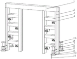
FIG. 1 is a schematic front view of the present invention;
FIG. 2 is a schematic view of the backside structure of the present invention;
FIG. 3 is a schematic cross-sectional view of the supporting device of the present invention;
FIG. 4 is a bottom view of the puck of the present invention;
FIG. 5 is a schematic view of the internal structure of the receiving groove of the present invention;
FIG. 6 is a schematic view of the pedaling apparatus according to the present invention.
In the figure: 1. portal crossbeam, 2, support frame, 3, trample the crossbeam, 4, trample the device, 5, the slot, 6, the bracing piece, 7, the fixing base, 8, support ejector pin, 9, the positioning disk, 10, the locating hole, 11, the location awl, 12, the friction awl, 13, the carousel, 14, accomodate the groove, 15, rotate the bolt, 16, the handrail, 17, the spout, 18, the receiver, 21, outer support frame, 22, inner support frame, 41, fixed frame, 42, the axis of rotation, 43, the footboard, 44, the spout, 45, torsion spring, 46, the sloping block, 47, the protection pad, 48, trample the groove, 49, the fixed axle.
Detailed Description
The technical solutions in the embodiments of the present invention will be clearly and completely described below with reference to the drawings in the embodiments of the present invention, and it is obvious that the described embodiments are only a part of the embodiments of the present invention, and not all of the embodiments. All other embodiments, which can be derived by a person skilled in the art from the embodiments given herein without making any creative effort, shall fall within the protection scope of the present invention.
The first embodiment is as follows:
referring to fig. 1-5, the present invention provides a technical solution: a door type scaffold for constructional engineering comprises a door frame beam 1, wherein two ends of the bottom of the door frame beam 1 are fixedly connected with support frames 2, two sides of one end, far away from the door frame beam 1, of each support frame 2 are provided with slots 5, the inner walls of the slots 5 are slidably connected with support rods 6, one ends, far away from the slots 5, of the support rods 6 are fixedly connected with fixing seats 7, the tops of the fixing seats 7 are penetrated through and are in threaded connection with support ejector rods 8, one ends, penetrating through the fixing seats 7, of the support ejector rods 8 are in threaded connection with positioning discs 9, the tops of the positioning discs 9 are provided with positioning holes 10, the inner walls of the positioning holes 10 are slidably connected with positioning cones 11, when the scaffold needs to be placed on hard ground, the scaffold can be placed on the ground and is supported through the support, the scaffold is leaned on a wall body, when the ground surface is uneven, the length of the supporting ejector rod 8 in the fixing seat 7 can be adjusted to enable the supporting ejector rod 8 to be abutted against the bottom of a hollow part, when the ground surface is soft, the positioning disc 9 can be installed at the bottom of the supporting ejector rod 8, the contact area between the supporting ejector rod 8 and the ground surface can be increased by the positioning disc 9, the scaffold is prevented from shaking caused by the fact that the supporting ejector rod 8 is inserted into the soft ground surface when the stress is large, the scaffold can be more stable by inserting the positioning cone 11 into the positioning disc 9, the supporting rod 6 is a flat hard metal rod with good rigidity, the supporting rod 6 is longitudinally inserted into the slot 5, the shape of the inner wall of the slot 5 is matched with the shape of the supporting rod 6, the relative strength of the supporting rod 6 can be increased, the scaffold is prevented from being inclined due to the fact that the supporting rod, the friction cones 12 are provided with a plurality of friction cones which are evenly distributed on the bottom surface of one end of the mandril 8, when the scaffold is used on a hard ground, the positioning disc 9 can be arranged at the bottom of the supporting mandril 8 according to the use requirement, because the ground can not be completely smooth, the friction cones 12 at the bottom of the positioning disc 9 can increase the friction force between the positioning disc 9 and the ground, thus the scaffold can be more stable,
portal crossbeam 1 and step on 3 one sides of crossbeam and all seted up and accomodate groove 14, portal crossbeam 1 communicates with each other with the groove 14 of accomodating on trampling crossbeam 3, accomodate 14 inner wall fixedly connected with rotation bolt 15 in the groove, the one end fixedly connected with regulation that accomodates 14 inner walls in the groove is kept away from to rotation bolt 15 is connected with handrail 16, handrail 16 keeps away from the one end that rotates bolt 15 and has seted up spout 17, spout 17 inner wall sliding connection has receiver 18, when the operating personnel health outwards explores, can follow and accomodate groove 14 with handrail 16 and roll out, the operating personnel health supports on the handrail, it is more stable when can making the health explore, and operating personnel can weave the instrument in receiver 18, directly take receiver 18 from spout 17 when needing to take out can.
Example two:
referring to fig. 1-6, on the basis of the first embodiment, the present invention provides a technical solution: a door type scaffold for construction engineering comprises a door frame beam 1, wherein two ends of the bottom of the door frame beam 1 are fixedly connected with support frames 2, a stepping beam 3 is fixedly connected between the support frames 2, one end of the bottom of the stepping beam 3 is fixedly connected with a stepping device 4, the stepping device 4 comprises a fixed frame 41, two sides of the inner wall of the fixed frame 41 are fixedly connected with a rotating shaft 42, one end of the rotating shaft 42, which is far away from the inner wall of the fixed frame 41, is rotatably connected with a pedal 43, the bottom of the pedal 43 and the bottom of the inner wall of the fixed frame 41 are respectively provided with a chute 44, the inner wall of the chute 44 is slidably connected with a torsion spring 45, the top of the inner wall of the fixed frame 41 is fixedly connected with an inclined block 46, one side of the inclined block 46, which is far away from the, when the foot of the user is inserted into the fixed frame 41, the foot can be placed in the treading groove 48 on the pedal 43, when the foot is inserted, the tip of the foot is used to press one end of the pedal 43 close to the torsion spring 45, the pedal 43 rotates around the rotating shaft 42 and compresses the torsion spring 45 until the tip of the foot reaches the bottom of one end of the treading groove 48 close to the torsion spring 45, at the moment, the foot is clamped between the pedal 43 and the inclined block 46, and the whole foot is placed in the treading groove 48, so that the sliding of the foot of the user can be prevented, the foot can not shake with the body when the body moves, the risk that the operator slides from the scaffold is reduced, the treading devices 4 are respectively arranged at the left end and the right end of the two adjacent treading beams 3, the treading grooves 48 in the treading devices 4 at the left end and the right end of the treading beams 3 are respectively matched with the shapes of the left foot and the right foot, when, the inner wall of the treading groove 48 can block the foot from sliding to the outside of the pedal 43.
The use method is exemplified by the following method,
place the scaffold frame subaerial, when needs use positioning disk 9, it is inside to support ejector pin 8 to insert fixing base 7, install positioning disk 9 in support ejector pin 8 bottom, rotatory support ejector pin 8, support ejector pin 8 rotates and moves down in fixing base 7 is inside, when supporting ejector pin 8 and moving to positioning disk 9 compress tightly subaerial, stall support ejector pin 8, insert locating cone 11 inside locating hole 10 and compress tightly, the user tramples and tramples crossbeam 3 and upwards scrambles, when climbing to the operation height, the user inserts inside fixed frame 41 with the foot, and prevent inside trampling groove 48, the user tramples the one end of pressing footboard 43 and being close to torsion spring 45 with the tiptoe, and insert between oblique piece 46 and footboard 43 with the tiptoe, can relax the foot when the tiptoe inserts to trampling groove 38 one end bottom.
It is noted that, herein, relational terms such as first and second, and the like may be used solely to distinguish one entity or action from another entity or action without necessarily requiring or implying any actual such relationship or order between such entities or actions. Also, the terms "comprises," "comprising," or any other variation thereof, are intended to cover a non-exclusive inclusion, such that a process, method, article, or apparatus that comprises a list of elements does not include only those elements but may include other elements not expressly listed or inherent to such process, method, article, or apparatus. The term "comprising", without further limitation, means that the element so defined is not excluded from the group consisting of additional identical elements in the process, method, article, or apparatus that comprises the element.
Although embodiments of the present invention have been shown and described, it will be appreciated by those skilled in the art that changes, modifications, substitutions and alterations can be made in these embodiments without departing from the principles and spirit of the invention, the scope of which is defined in the appended claims and their equivalents. .
Claims (10)
1. The utility model provides a door-type scaffold for building engineering, includes portal crossbeam (1), its characterized in that: the device is characterized in that support frames (2) are fixedly connected to both ends of the bottom of the portal beam (1), trample beams (3) are fixedly connected between the support frames (2), a trample device (4) is fixedly connected to one end of the bottom of the trample beams (3), slots (5) are formed in both sides of one end, far away from the portal beam (1), of each support frame (2), a support rod (6) is slidably connected to the inner wall of each slot (5), a fixing seat (7) is fixedly connected to one end, far away from the slots (5), of each support rod (6), a support ejector rod (8) is connected to the top of each fixing seat (7) in a penetrating and threaded mode, a positioning disc (9) is connected to one end, penetrating through each fixing seat (7), of each support ejector rod (8) in a threaded mode, a positioning, the door frame cross beam (1) and the trampling cross beam (3) are respectively provided with an accommodating groove (14) at one side, the door frame cross beam (1) and the accommodating grooves (14) on the trampling cross beam (3) are communicated with each other, the inner wall of each accommodating groove (14) is fixedly connected with a rotating bolt (15), one end, far away from the inner wall of each accommodating groove (14), of each rotating bolt (15) is fixedly connected with a handrail (16) in a specified manner, one end, far away from the rotating bolt (15), of each handrail (16) is provided with a sliding groove (17), and the inner wall of each sliding groove (17) is connected with an accommodating;
trample device (4) including fixed frame (41), the equal fixedly connected with axis of rotation (42) in fixed frame (41) inner wall both sides, the one end rotation of keeping away from fixed frame (41) inner wall in axis of rotation (42) is connected with footboard (43), spout (44) have all been seted up to footboard (43) bottom and fixed frame (41) inner wall bottom, spout (44) inner wall sliding connection has torsion spring (45), fixed frame (41) inner wall top fixedly connected with sloping block (46), one side fixedly connected with protection pad (47) at fixed frame (41) inner wall top are kept away from to sloping block (46), footboard (43) top has been seted up and has been trampled groove (48).
2. A door type scaffold for construction engineering according to claim 1, wherein: the support frame (2) comprises an outer support frame (21) and an inner support frame (22), the treading cross beam (3) is fixed between the outer support frame (21) and the inner support frame (22), and two groups of support frames (2) are arranged and fixed at two ends of the gantry cross beam (1).
3. A door type scaffold for construction engineering according to claim 1, wherein: trample device (4) and set up respectively at the left end and the right-hand member of double-phase adjacent trampling crossbeam (3), trample groove (48) in trampling device (4) of trampling crossbeam (3) left end and right-hand member respectively with the shape looks adaptation of left foot and right foot.
4. A door type scaffold for construction engineering according to claim 3, wherein: the support rod (6) is a hard metal rod with good flat rigidity, the support rod (6) is longitudinally inserted into the slot (5), and the shape of the inner wall of the slot (5) is matched with that of the support rod (6).
5. A door type scaffold for construction engineering according to claim 1, wherein: the friction cone (12) is arranged on the bottom surface of one end, close to the positioning disc (9), of the supporting ejector rod (8), the friction cone (12) is provided with a plurality of friction cones which are evenly distributed on the bottom surface of one end of the ejector rod (8), and the ejector rod (8) is far away from the turntable (13) fixedly connected with one end of the positioning disc (9).
6. A door type scaffold for construction engineering according to claim 1, wherein: the two positioning holes (10) are arranged and are symmetrically distributed on the top of the positioning disc (9) relative to the circle center of the positioning disc (9).
7. A door type scaffold for construction engineering according to claim 1, wherein: both ends of the bottom of the inner wall of the fixed frame (41) are provided with torsion springs (45), the inner wall of each torsion spring (45) is slidably connected with a fixed shaft (49), and both ends of each fixed shaft (49) are fixedly connected with both sides of the inner wall of the fixed frame (41) respectively.
8. A door type scaffold for construction engineering according to claim 2, wherein: the slots (5) are formed in two sides of the bottom of the outer support frame (21).
9. A door type scaffold for construction engineering according to claim 1, wherein: the size of the sliding groove (44) is matched with the diameter of the leg of the torsion spring (45), and the part of the leg of the torsion spring (45) positioned in the sliding groove (44) is parallel to the bottom of the inner wall of the sliding groove (44).
10. A door type scaffold for construction engineering according to claim 1, wherein: the protective pad (47) is made of a rubber soft pad with a rough surface.
Priority Applications (1)
| Application Number | Priority Date | Filing Date | Title |
|---|---|---|---|
| CN202010597118.2A CN111663757A (en) | 2020-06-28 | 2020-06-28 | Door-type scaffold for building engineering |
Applications Claiming Priority (1)
| Application Number | Priority Date | Filing Date | Title |
|---|---|---|---|
| CN202010597118.2A CN111663757A (en) | 2020-06-28 | 2020-06-28 | Door-type scaffold for building engineering |
Publications (1)
| Publication Number | Publication Date |
|---|---|
| CN111663757A true CN111663757A (en) | 2020-09-15 |
Family
ID=72390066
Family Applications (1)
| Application Number | Title | Priority Date | Filing Date |
|---|---|---|---|
| CN202010597118.2A Pending CN111663757A (en) | 2020-06-28 | 2020-06-28 | Door-type scaffold for building engineering |
Country Status (1)
| Country | Link |
|---|---|
| CN (1) | CN111663757A (en) |
Cited By (2)
| Publication number | Priority date | Publication date | Assignee | Title |
|---|---|---|---|---|
| CN112832500A (en) * | 2020-12-31 | 2021-05-25 | 孙学志 | Energy-conserving construction lift anti-falling device |
| CN114855564A (en) * | 2022-05-23 | 2022-08-05 | 蓝海绿业生态建设股份有限公司 | Garden ground paving equipment and construction method |
Citations (8)
| Publication number | Priority date | Publication date | Assignee | Title |
|---|---|---|---|---|
| DE3505917A1 (en) * | 1985-02-21 | 1986-08-21 | Krause-Werk Gmbh & Co Kg, 6320 Alsfeld | Working platform |
| CN105952370A (en) * | 2016-05-22 | 2016-09-21 | 陈烁 | Glide ladder |
| CN107956414A (en) * | 2018-01-12 | 2018-04-24 | 海宁市盈向家居设计有限公司 | A kind of finishing aerial ladder easy to storage |
| CN207363581U (en) * | 2017-10-13 | 2018-05-15 | 浦江概念五金科技有限公司 | A kind of handrail is foldable and the suppressible double ladder of spike |
| CN208380036U (en) * | 2018-05-11 | 2019-01-15 | 林寿娣 | A kind of highly-safe construction scaffold |
| CN209780183U (en) * | 2019-02-26 | 2019-12-13 | 安徽省永安建筑有限公司 | scaffolding for construction |
| CN209780174U (en) * | 2019-03-20 | 2019-12-13 | 金环建设集团有限公司 | Scaffold for building construction |
| CN210530712U (en) * | 2018-07-25 | 2020-05-15 | 沈阳一鸿机电设备安装工程有限公司 | Air conditioner installation safety ladder |
-
2020
- 2020-06-28 CN CN202010597118.2A patent/CN111663757A/en active Pending
Patent Citations (8)
| Publication number | Priority date | Publication date | Assignee | Title |
|---|---|---|---|---|
| DE3505917A1 (en) * | 1985-02-21 | 1986-08-21 | Krause-Werk Gmbh & Co Kg, 6320 Alsfeld | Working platform |
| CN105952370A (en) * | 2016-05-22 | 2016-09-21 | 陈烁 | Glide ladder |
| CN207363581U (en) * | 2017-10-13 | 2018-05-15 | 浦江概念五金科技有限公司 | A kind of handrail is foldable and the suppressible double ladder of spike |
| CN107956414A (en) * | 2018-01-12 | 2018-04-24 | 海宁市盈向家居设计有限公司 | A kind of finishing aerial ladder easy to storage |
| CN208380036U (en) * | 2018-05-11 | 2019-01-15 | 林寿娣 | A kind of highly-safe construction scaffold |
| CN210530712U (en) * | 2018-07-25 | 2020-05-15 | 沈阳一鸿机电设备安装工程有限公司 | Air conditioner installation safety ladder |
| CN209780183U (en) * | 2019-02-26 | 2019-12-13 | 安徽省永安建筑有限公司 | scaffolding for construction |
| CN209780174U (en) * | 2019-03-20 | 2019-12-13 | 金环建设集团有限公司 | Scaffold for building construction |
Cited By (2)
| Publication number | Priority date | Publication date | Assignee | Title |
|---|---|---|---|---|
| CN112832500A (en) * | 2020-12-31 | 2021-05-25 | 孙学志 | Energy-conserving construction lift anti-falling device |
| CN114855564A (en) * | 2022-05-23 | 2022-08-05 | 蓝海绿业生态建设股份有限公司 | Garden ground paving equipment and construction method |
Similar Documents
| Publication | Publication Date | Title |
|---|---|---|
| CN107463223B (en) | Heat dissipation type mainframe box convenient to use | |
| CN111663757A (en) | Door-type scaffold for building engineering | |
| CN211230196U (en) | Outdoor staircase for housing construction engineering | |
| CN110905184A (en) | Hanging flower basket for construction | |
| CN212201195U (en) | Scaffold for construction | |
| CN211817803U (en) | Construction platform convenient to remove | |
| CN210551885U (en) | Furniture processing table bed with adjustable inclination angle | |
| CN214246536U (en) | A scaffolding that is easy to move | |
| CN212739037U (en) | Steel furniture piece collection device | |
| CN113386209B (en) | Thicknesser machine with unloading mechanism is lifted in self-interacting | |
| CN212491378U (en) | Device is tempered with shank to old nursing | |
| CN214330503U (en) | A kind of cable shaft wellhead climbing ladder | |
| CN219011852U (en) | Scaffold suitable for uneven ground | |
| CN222731471U (en) | Installation ladder for electromechanical engineering | |
| CN221463358U (en) | Building engineering quality detection device | |
| CN214282090U (en) | Honey peach tree is planted with digging device | |
| CN2892185Y (en) | Multifunctional abdomen body building device | |
| CN218324702U (en) | A climbing bracket applied to vegetable planting | |
| CN222322349U (en) | Lodging-resistant protective bracket for fixed and firm forest | |
| CN219638338U (en) | Wood floor splicing and calibrating tool | |
| CN222595455U (en) | Building engineering building climbing frame | |
| CN223881091U (en) | Movable ladder of ascending a height | |
| CN213428976U (en) | Place stable aluminium alloy easel | |
| CN213509506U (en) | Fitment is with being convenient for remove adjustable scaffold | |
| CN216341853U (en) | Highly be convenient for remove ladder of regulation |
Legal Events
| Date | Code | Title | Description |
|---|---|---|---|
| PB01 | Publication | ||
| PB01 | Publication | ||
| SE01 | Entry into force of request for substantive examination | ||
| SE01 | Entry into force of request for substantive examination | ||
| RJ01 | Rejection of invention patent application after publication |
Application publication date: 20200915 |
|
| RJ01 | Rejection of invention patent application after publication |