CN111663609B - Rotary cutoff water valve mechanism for kitchen sink - Google Patents

Rotary cutoff water valve mechanism for kitchen sink Download PDF

Info

Publication number
CN111663609B
CN111663609B CN202010400052.3A CN202010400052A CN111663609B CN 111663609 B CN111663609 B CN 111663609B CN 202010400052 A CN202010400052 A CN 202010400052A CN 111663609 B CN111663609 B CN 111663609B
Authority
CN
China
Prior art keywords
sleeve
fixed sleeve
fixed
rotary
water
Prior art date
Legal status (The legal status is an assumption and is not a legal conclusion. Google has not performed a legal analysis and makes no representation as to the accuracy of the status listed.)
Active
Application number
CN202010400052.3A
Other languages
Chinese (zh)
Other versions
CN111663609A (en
Inventor
罗守蓉
Current Assignee (The listed assignees may be inaccurate. Google has not performed a legal analysis and makes no representation or warranty as to the accuracy of the list.)
Guangdong Zhong'ou Bathroom Accessories Co ltd
Heshan Jinzhou Copper Industrial Co ltd
Original Assignee
Guangdong Zhong'ou Bathroom Accessories Co ltd
Priority date (The priority date is an assumption and is not a legal conclusion. Google has not performed a legal analysis and makes no representation as to the accuracy of the date listed.)
Filing date
Publication date
Application filed by Guangdong Zhong'ou Bathroom Accessories Co ltd filed Critical Guangdong Zhong'ou Bathroom Accessories Co ltd
Priority to CN202010400052.3A priority Critical patent/CN111663609B/en
Publication of CN111663609A publication Critical patent/CN111663609A/en
Application granted granted Critical
Publication of CN111663609B publication Critical patent/CN111663609B/en
Active legal-status Critical Current
Anticipated expiration legal-status Critical

Links

Images

Classifications

    • EFIXED CONSTRUCTIONS
    • E03WATER SUPPLY; SEWERAGE
    • E03CDOMESTIC PLUMBING INSTALLATIONS FOR FRESH WATER OR WASTE WATER; SINKS
    • E03C1/00Domestic plumbing installations for fresh water or waste water; Sinks
    • E03C1/02Plumbing installations for fresh water
    • E03C1/04Water-basin installations specially adapted to wash-basins or baths
    • FMECHANICAL ENGINEERING; LIGHTING; HEATING; WEAPONS; BLASTING
    • F16ENGINEERING ELEMENTS AND UNITS; GENERAL MEASURES FOR PRODUCING AND MAINTAINING EFFECTIVE FUNCTIONING OF MACHINES OR INSTALLATIONS; THERMAL INSULATION IN GENERAL
    • F16KVALVES; TAPS; COCKS; ACTUATING-FLOATS; DEVICES FOR VENTING OR AERATING
    • F16K11/00Multiple-way valves, e.g. mixing valves; Pipe fittings incorporating such valves
    • F16K11/02Multiple-way valves, e.g. mixing valves; Pipe fittings incorporating such valves with all movable sealing faces moving as one unit
    • F16K11/08Multiple-way valves, e.g. mixing valves; Pipe fittings incorporating such valves with all movable sealing faces moving as one unit comprising only taps or cocks
    • F16K11/085Multiple-way valves, e.g. mixing valves; Pipe fittings incorporating such valves with all movable sealing faces moving as one unit comprising only taps or cocks with cylindrical plug
    • F16K11/0856Multiple-way valves, e.g. mixing valves; Pipe fittings incorporating such valves with all movable sealing faces moving as one unit comprising only taps or cocks with cylindrical plug having all the connecting conduits situated in more than one plane perpendicular to the axis of the plug
    • EFIXED CONSTRUCTIONS
    • E03WATER SUPPLY; SEWERAGE
    • E03CDOMESTIC PLUMBING INSTALLATIONS FOR FRESH WATER OR WASTE WATER; SINKS
    • E03C1/00Domestic plumbing installations for fresh water or waste water; Sinks
    • E03C1/02Plumbing installations for fresh water
    • E03C1/04Water-basin installations specially adapted to wash-basins or baths
    • E03C2001/0414Water-basin installations specially adapted to wash-basins or baths allowing different orientations of the spout or the outlet nozzle

Landscapes

  • Engineering & Computer Science (AREA)
  • General Engineering & Computer Science (AREA)
  • Health & Medical Sciences (AREA)
  • Life Sciences & Earth Sciences (AREA)
  • Hydrology & Water Resources (AREA)
  • Public Health (AREA)
  • Water Supply & Treatment (AREA)
  • Mechanical Engineering (AREA)
  • Domestic Plumbing Installations (AREA)
  • Sliding Valves (AREA)

Abstract

本发明涉及旋转水龙头设备技术领域,且公开了一种用于厨房水槽的旋转断流式水阀机构,包括固定套筒,固定套筒内腔的顶部活动套接有旋转套筒,旋转套筒的外表面设有固定压板,且固定压板通过内六角螺栓与固定套筒的顶部固定连接,固定套筒包括固定套管,固定套管的内部开设有密封凹槽,固定套管内腔顶部的两侧均设一组有通流槽孔。该用于厨房水槽的旋转断流式水阀机构,对于密封凹槽的设置,并配合固定压板,可以在固定套筒与旋转套筒之间形成一个有效的水封机构,与现有的橡胶圈密封技术相比,该旋转式水龙头的密封性较好,使其在长期的旋转使用的过程中不会出现漏水的现象,稳定性及可靠性较高且使用寿命较长。

Figure 202010400052

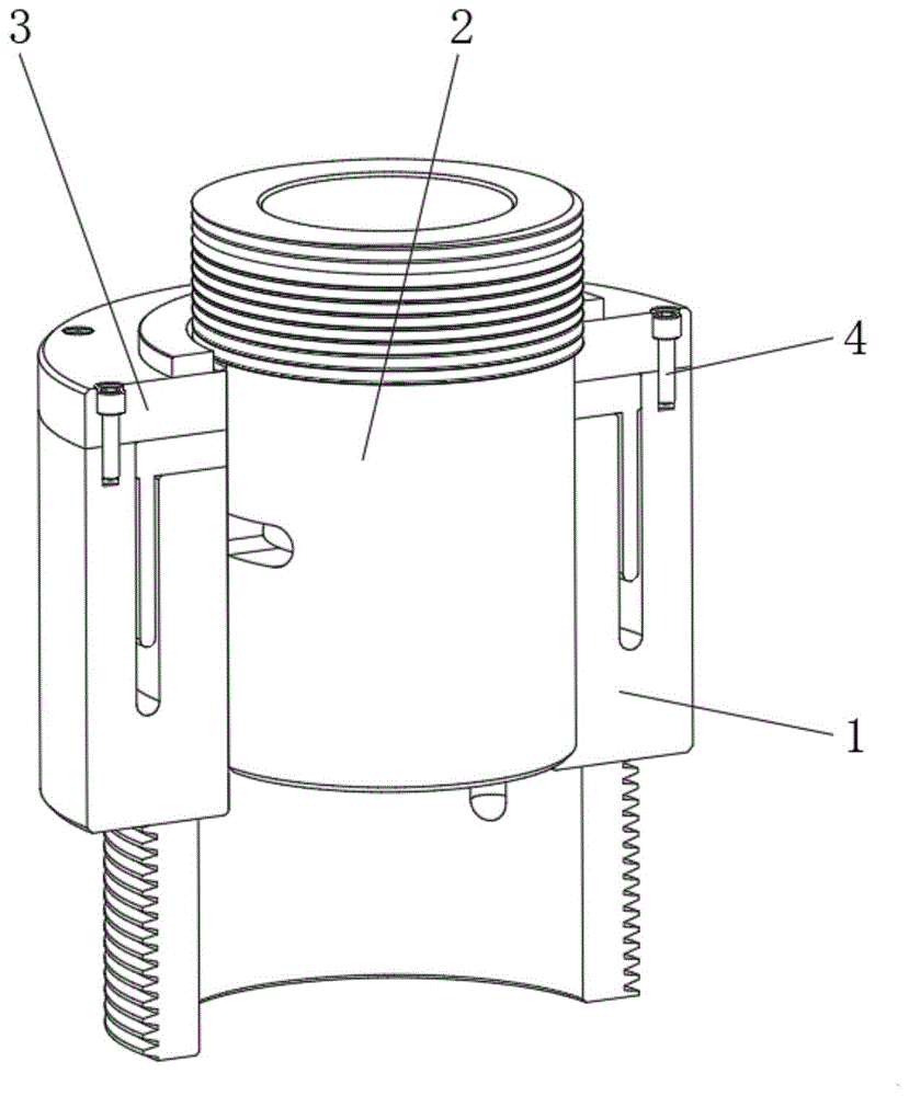
The invention relates to the technical field of rotary faucet equipment, and discloses a rotary cut-off water valve mechanism for a kitchen sink, comprising a fixed sleeve, the top of the inner cavity of the fixed sleeve is movably sleeved with a rotating sleeve, and the rotating sleeve There is a fixed pressure plate on the outer surface of the fixed pressure plate, and the fixed pressure plate is fixedly connected with the top of the fixed sleeve through the inner hexagon bolt. The fixed sleeve includes a fixed sleeve, and the interior of the fixed sleeve is provided with a sealing groove. Each side is provided with a set of through-flow slot holes. The rotary cut-off water valve mechanism for kitchen sinks can form an effective water sealing mechanism between the fixed sleeve and the rotating sleeve for the setting of the sealing groove and the fixed pressure plate, which is incompatible with the existing rubber Compared with the ring sealing technology, the rotary faucet has better sealing performance, so that there will be no water leakage during long-term rotating use, and the stability and reliability are high and the service life is long.

Figure 202010400052

Description

Rotary cutoff water valve mechanism for kitchen sink
Technical Field
The invention relates to the technical field of rotary faucet equipment, in particular to a rotary cutoff water valve mechanism for a kitchen sink.
Background
At present, in order to satisfy daily life in the kitchen to the separately clean and handle of vegetables or tableware, current kitchen sink is mostly two basin formula structural design, consequently, in order to adapt to the user demand of two basin structures, can be equipped with rotatable tap in its middle part position to the rotation that makes a round trip between two basins satisfies the water demand of two basins.
However, the existing rotary faucet has only one control valve, so that when the rotary faucet is rotated back and forth between two water tanks for use, or the water valve is closed first and then the water valve is opened to drain water after the water valve is rotated, so that the operation of the rotary faucet is complex and inconvenient when the rotary faucet is rotated for use, or the rotary faucet is directly rotated to another water tank without closing the water valve, so that the phenomenon that water splash is generated due to water flow impacting on the wall of the water tank can occur, not only is the waste of water resources caused, but also the ground can cause wet slipping due to splashed water splash, the phenomenon of unbalanced slipping is easily generated in the process that a person walks back and forth, and further the existing rotary faucet is poor in use effect, the operation is inconvenient when the water is rotated between two water tanks for water drainage, and certain potential safety hazards are easily caused due to the splashed water splash.
Disclosure of Invention
Technical problem to be solved
The invention provides a rotary cut-off water valve mechanism for kitchen sinks, which has the advantages of automatically controlling the on-off of water flow when two sinks rotate and preventing water splash from splashing without specially adjusting a control valve when the sinks rotate, solves the problem that the existing rotary water faucet only has one control valve, therefore, when the rotary faucet is used by rotating back and forth between two water tanks, or the water valve is firstly closed and then the water valve is opened to drain water after the rotation is finished, so that the operation of the rotary faucet is more complicated and extremely inconvenient when the rotary faucet is used by rotating, or the rotary faucet is directly rotated to another water tank without closing the water valve, the water flow impacts the wall of the water tank to cause splashing of water, so that water resources are wasted, the ground is wet and slippery due to splashed water, and the problem of unbalanced slipping is easily caused in the process of back and forth movement of personnel.
(II) technical scheme
The invention provides the following technical scheme: a rotary cutoff water valve mechanism for a kitchen sink comprises a fixed sleeve, a rotary sleeve, a fixed pressing plate and an inner hexagon bolt, wherein the rotary sleeve is movably sleeved at the top of an inner cavity of the fixed sleeve, the fixed pressing plate is arranged on the outer surface of the rotary sleeve and is fixedly connected with the top of the fixed sleeve through the inner hexagon bolt, the fixed sleeve comprises a fixed sleeve, a sealing groove is formed in the fixed sleeve, a set of through-flow slot holes are formed in the two sides of the top of the inner cavity of the fixed sleeve, connecting pipe grooves are formed in the two sides of the inner cavity of the fixed sleeve, the top and the bottom of the inner cavity of the fixed sleeve are communicated with each other through the upper end and the lower end of each connecting pipe groove, the rotary sleeve comprises a rotary sleeve, the bottom of the outer surface of the rotary sleeve is movably sleeved with the top of the inner cavity of the fixed sleeve, and, and the bottom end of the sealing protection wall extends to the inside of the sealing groove, the left side and the right side inside the rotary sleeve are respectively provided with a connecting slotted hole I and a connecting slotted hole II, and a single-group communicated position angle exists between the connecting slotted hole I and the connecting slotted hole II and two groups of through-flow slotted holes on the fixed sleeve respectively.
Preferably, the outer part of the fixing sleeve is provided with an upper boss structure and a lower boss structure, and the bottom of the outer surface of the fixing sleeve is provided with an external thread.
Preferably, the sealing groove divides the upper part of the fixing sleeve into an inner annular structure and an outer annular structure, the top end of the inner annular structure is lower than the top end of the outer annular structure, the width of the inner part of the sealing groove is larger than the thickness of the bottom of the sealing protection wall, and the inner part of the sealing groove is filled with non-toxic colloidal liquid with one third of the height.
Preferably, the thickness of the bottom of the sealing protection wall is equal to the height difference of the inner annular structure and the outer annular structure of the upper part of the fixed sleeve.
Preferably, the outer parts of the connecting slot I and the connecting slot II are both designed to be in a kidney-shaped hole shape, and an included angle of 60 degrees is formed between the central lines of the connecting slot I and the connecting slot II.
Preferably, the bottom of the inner cavity of the rotary sleeve is provided with a hemispherical structure, and the top of the outer surface of the inner cavity of the rotary sleeve is provided with an external thread.
(III) advantageous effects
The invention has the following beneficial effects:
1. this a rotatory formula water valve mechanism that cuts off current for kitchen sink, to the through-flow slotted hole, connect slotted hole I and connect the setting of slotted hole II, a set of through-flow slotted hole on the fixed sleeving that will automatic shutoff of rotating sleeve pipe after this water valve mechanism is rotatory to certain angle, another set of through-flow slotted hole will be linked together with being connected slotted hole I or being connected between the slotted hole II on the fixed sleeving after continuing to rotate, compare with current rotation type tap, in the in-process that makes a round trip to rotate the use, can realize the automatic on-off control to rivers, and no longer need close the control water valve, or because of rivers impact cell wall causes the splash of watering, neither can cause the waste of water resource, also can not cause the wet and slippery phenomenon in ground, reliability and result of use are better.
2. This a rotatory formula water valve mechanism that cuts off current for kitchen sink to the setting of sealed recess, simultaneously and cooperation fixed pressing plate, can form an effectual water seal mechanism between fixed sleeve and rotatory sleeve, compares with current rubber circle sealing technique, and this rotation type tap's leakproofness is better, makes its phenomenon that can not appear leaking at long-term rotatory in-process of using, and stability and reliability are higher and life are longer.
Drawings
FIG. 1 is a schematic structural view of the present invention;
FIG. 2 is a schematic structural view of the fixing sleeve of the present invention;
FIG. 3 is a schematic view of the structure of the rotating sleeve of the present invention;
fig. 4 is a schematic structural view of the fixed platen of the present invention.
In the figure: 1. fixing the sleeve; 11. fixing the sleeve; 12. sealing the groove; 13. a through-flow slot; 14. connecting a pipe groove; 2. rotating the sleeve; 21. rotating the sleeve; 22. sealing the protecting wall; 23. connecting the slotted hole I; 24. a connecting slot II; 3. fixing the pressing plate; 4. and (4) an inner hexagon bolt.
Detailed Description
The technical solutions in the embodiments of the present invention will be clearly and completely described below with reference to the drawings in the embodiments of the present invention, and it is obvious that the described embodiments are only a part of the embodiments of the present invention, and not all of the embodiments. All other embodiments, which can be derived by a person skilled in the art from the embodiments given herein without making any creative effort, shall fall within the protection scope of the present invention.
Referring to fig. 1-4, a rotary cutoff water valve mechanism for a kitchen sink comprises a fixed sleeve 1, a rotary sleeve 2, a fixed pressing plate 3 and an inner hexagon bolt 4, wherein the top of the inner cavity of the fixed sleeve 1 is movably sleeved with the rotary sleeve 2, the outer surface of the rotary sleeve 2 is provided with the fixed pressing plate 3, the fixed pressing plate 3 is fixedly connected with the top of the fixed sleeve 1 through the inner hexagon bolt 4, the fixed sleeve 1 comprises a fixed sleeve 11, the fixed sleeve 11 is internally provided with a sealing groove 12, both sides of the top of the inner cavity of the fixed sleeve 11 are provided with a set of through-flow slot holes 13, both sides of the inside of the fixed sleeve 11 are provided with connecting tube slots 14, the upper end and the lower end of each connecting tube slot 14 communicate the top and the bottom of the inner cavity of the fixed sleeve 11, the rotary sleeve 2 comprises a rotary sleeve 21, the bottom of the outer surface of the rotary sleeve 21 is, the top of the outer surface of the rotating sleeve 21 is provided with a sealing guard wall 22, the bottom end of the sealing guard wall 22 extends into the sealing groove 12, the left side and the right side of the inside of the rotating sleeve 21 are respectively provided with a connecting slotted hole I23 and a connecting slotted hole II 24, and a single-group communicated position angle exists between the connecting slotted hole I23 and the connecting slotted hole II 24 and the two groups of through-flow slotted holes 13 on the fixed sleeve 11.
Wherein, to the sectional type structure setting between this water valve mechanism and the tap, make it can change impaired water valve mechanism or tap respectively at the in-process of long-term use, can only carry out whole change for current rotation type tap integral type structural design, it is lower at the cost of manufacturing and use maintenance, and application scope is wider.
In this technical scheme, the outside of fixed sleeve 11 is established to upper and lower two sets of boss formula structures, and is equipped with the external screw thread in the bottom of its surface.
Wherein, to the setting of fixed sleeve 11 exterior structure to in its bottom threaded connection have running water and day hot water pipeline, made simultaneously on it each structure set up the outward appearance more pleasing to the eye, can not appear uncoordinated arch.
In this technical scheme, sealed recess 12 will fix the upper portion of sleeve pipe 11 and be two inside and outside annular structure, and the top of its interior annular structure will be less than outer annular structure, and the inside width of sealed recess 12 is greater than the thickness of sealed dado 22 bottom simultaneously to the nontoxic colloidal liquid of one-third height is filled in the inside of sealed recess 12.
In this embodiment, the thickness of the bottom of the sealing retaining wall 22 is equal to the height difference between the inner and outer annular structures of the upper portion of the fixed sleeve 11.
Wherein, to the setting of sealed recess 12 to cooperation fixed pressing plate 3 can form an effectual water seal mechanism between fixed sleeve 1 and rotatory sleeve 2, makes this rotation type tap in the long-term rotatory in-process of using, the phenomenon that can not appear leaking, and stability and reliability are higher and life are longer.
In the technical scheme, the outer parts of the connecting slotted hole I23 and the connecting slotted hole II 24 are both designed to be in a kidney-shaped hole shape, and an included angle of 60 degrees is formed between the central lines of the connecting slotted hole I23 and the connecting slotted hole II 24.
When the water valve mechanism rotates to a certain angle, the rotating sleeve 21 automatically plugs one group of through-flow slots 13 on the fixed sleeve 11, and the other group of through-flow slots 13 on the fixed sleeve 11 are communicated with the connecting slots I23 or the connecting slots II 24 after the rotating sleeve rotates continuously, so that when the rotating faucet is rotated between two water tanks, the automatic flow-cut-off and plugging operation of the rotating faucet in a certain angle range is realized, and the phenomenon that water splash is caused when water flow impacts the wall of the water tank is prevented.
In the technical scheme, the bottom of the inner cavity of the rotating sleeve 21 is provided with a hemispherical structure, and the top of the outer surface of the rotating sleeve is provided with an external thread.
The use method and the working principle of the embodiment are as follows:
firstly, according to the general installation and connection method of the water tap, the cut-off type water valve mechanism is installed between the water tap and the control water valve by utilizing the external threads on the rotary sleeve 21 and the fixed sleeve 11, the central axis between the connecting slotted hole I23 and the connecting slotted hole II 24 is kept consistent with the slot wall between the two water slots, then the tap water pipe and the hot water pipeline are communicated, when water needs to be discharged in the left water slot, the water tap can be directly rotated without closing the control water valve, the rotary sleeve 21 is driven to rotate while the water tap is rotated, so that the through-flow slotted hole 13 and the connecting slotted hole II 24 which are mutually communicated on the right side are staggered, meanwhile, the through-flow slotted hole 13 on the right side is not mutually communicated with the connecting slotted hole I23, the water through slot of the water tap is temporarily blocked, and further, when the water splashes through the water slot wall, the phenomenon of water splash can not occur, then, the faucet is continuously rotated to drive the rotating sleeve 21 to rotate until the rotating sleeve moves to the middle position of the left water tank, the through-flow slot hole 13 on the left side and the connecting slot hole I23 are communicated with each other, water flow conveyed by a tap water pipe and a hot water pipeline passes through the connecting pipe groove 14 on the left side and is discharged from the faucet, and a channel between the through-flow slot hole 13 on the right side and the connecting slot hole II 24 is continuously blocked; when water needs to be discharged from the right water tank, the water faucet is directly rotated to some extent, meanwhile, a channel between the left through-flow slot hole 13 and the connecting slot hole I23 is gradually plugged, after the water faucet is rotated to a certain angle, a channel between the right through-flow slot hole 13 and the connecting slot hole II 24 is gradually opened, so that water flow is discharged through the channel, meanwhile, a channel between the left through-flow slot hole 13 and the connecting slot hole I23 is plugged, and therefore when the water faucet is used in a back-and-forth rotating mode between two water tanks, a control water valve is not required to be closed, or the phenomenon that water splash is caused by water flow impacting the water tank walls is avoided, and the water faucet is convenient to use and high in stability.
It is noted that, herein, relational terms such as first and second, and the like may be used solely to distinguish one entity or action from another entity or action without necessarily requiring or implying any actual such relationship or order between such entities or actions. Also, the terms "comprises," "comprising," or any other variation thereof, are intended to cover a non-exclusive inclusion, such that a process, method, article, or apparatus that comprises a list of elements does not include only those elements but may include other elements not expressly listed or inherent to such process, method, article, or apparatus.
Although embodiments of the present invention have been shown and described, it will be appreciated by those skilled in the art that changes, modifications, substitutions and alterations can be made in these embodiments without departing from the principles and spirit of the invention, the scope of which is defined in the appended claims and their equivalents.

Claims (5)

1. The utility model provides a rotatory outage formula water valve mechanism for kitchen sink, includes fixed sleeve (1), rotatory sleeve (2), fixed clamp plate (3) and hexagon socket head cap screw (4), rotatory sleeve (2) have been cup jointed in the top activity of fixed sleeve (1) inner chamber, the surface of rotatory sleeve (2) is equipped with fixed clamp plate (3), and fixed clamp plate (3) through the top fixed connection of hexagon socket head cap screw (4) and fixed sleeve (1), its characterized in that: the fixed sleeve (1) comprises a fixed sleeve (11), a sealing groove (12) is formed in the fixed sleeve (11), a group of through-flow slotted holes (13) are formed in the two sides of the top of an inner cavity of the fixed sleeve (11), connecting pipe grooves (14) are formed in the two sides of the inner cavity of the fixed sleeve (11), the upper end and the lower end of each connecting pipe groove (14) are used for communicating the top and the bottom of the inner cavity of the fixed sleeve (11), the rotary sleeve (2) comprises a rotary sleeve (21), the bottom of the outer surface of the rotary sleeve (21) is movably sleeved with the top of the inner cavity of the fixed sleeve (11), a sealing protection wall (22) is arranged at the top of the outer surface of the rotary sleeve (21), the bottom end of the sealing protection wall (22) extends into the sealing groove (12), and the sealing groove (12) divides the upper portion of the fixed sleeve (11) into an inner annular structure and an, the top end of the inner annular structure is lower than the outer annular structure, the width of the inner part of the sealing groove (12) is larger than the thickness of the bottom of the sealing guard wall (22), the inner part of the sealing groove (12) is filled with one third of non-toxic colloidal liquid, the left side and the right side of the inner part of the rotating sleeve (21) are respectively provided with a connecting groove hole I (23) and a connecting groove hole II (24), and a single-group communicated position angle exists between the connecting groove hole I (23) and the connecting groove hole II (24) and two groups of through-flow groove holes (13) in the fixed sleeve (11).
2. A rotary shut off water valve mechanism for a kitchen sink as claimed in claim 1, wherein: the outer part of the fixed sleeve (11) is provided with an upper boss structure and a lower boss structure, and the bottom of the outer surface of the fixed sleeve is provided with an external thread.
3. A rotary shut off water valve mechanism for a kitchen sink as claimed in claim 1, wherein: the thickness of the bottom of the sealing protection wall (22) is equal to the height difference of the inner annular structure and the outer annular structure of the upper part of the fixed sleeve (11).
4. A rotary shut off water valve mechanism for a kitchen sink as claimed in claim 1, wherein: the outer parts of the connecting slotted hole I (23) and the connecting slotted hole II (24) are both in a kidney-shaped hole shape, and an included angle of 60 degrees is formed between the central lines of the connecting slotted hole I (23) and the connecting slotted hole II (24).
5. A rotary shut off water valve mechanism for a kitchen sink as claimed in claim 1, wherein: the bottom of the inner cavity of the rotary sleeve (21) is provided with a hemispherical structure, and the top of the outer surface of the rotary sleeve is provided with an external thread.
CN202010400052.3A 2020-05-13 2020-05-13 Rotary cutoff water valve mechanism for kitchen sink Active CN111663609B (en)

Priority Applications (1)

Application Number Priority Date Filing Date Title
CN202010400052.3A CN111663609B (en) 2020-05-13 2020-05-13 Rotary cutoff water valve mechanism for kitchen sink

Applications Claiming Priority (1)

Application Number Priority Date Filing Date Title
CN202010400052.3A CN111663609B (en) 2020-05-13 2020-05-13 Rotary cutoff water valve mechanism for kitchen sink

Publications (2)

Publication Number Publication Date
CN111663609A CN111663609A (en) 2020-09-15
CN111663609B true CN111663609B (en) 2021-06-01

Family

ID=72383476

Family Applications (1)

Application Number Title Priority Date Filing Date
CN202010400052.3A Active CN111663609B (en) 2020-05-13 2020-05-13 Rotary cutoff water valve mechanism for kitchen sink

Country Status (1)

Country Link
CN (1) CN111663609B (en)

Citations (6)

* Cited by examiner, † Cited by third party
Publication number Priority date Publication date Assignee Title
CN102536925A (en) * 2012-01-05 2012-07-04 解始建 Hydraulic automatic reciprocating booster
CN106763902A (en) * 2017-01-10 2017-05-31 重庆超力高科技股份有限公司 Valve element and valve
CN106895177A (en) * 2017-03-28 2017-06-27 龙岩鸿航卫浴有限公司 Water outlet is used as the tap for switching
CN108869802A (en) * 2018-09-12 2018-11-23 苏州丹顿机电有限公司 A kind of Cold-hot water valve
EP3584477A1 (en) * 2014-08-28 2019-12-25 Greg Rowe Limited Water tap body and installation
CN210106676U (en) * 2019-05-22 2020-02-21 九牧厨卫股份有限公司 a faucet

Family Cites Families (1)

* Cited by examiner, † Cited by third party
Publication number Priority date Publication date Assignee Title
CN104846971B (en) * 2014-02-17 2016-06-29 成霖企业股份有限公司 A rotary hammer assembly

Patent Citations (6)

* Cited by examiner, † Cited by third party
Publication number Priority date Publication date Assignee Title
CN102536925A (en) * 2012-01-05 2012-07-04 解始建 Hydraulic automatic reciprocating booster
EP3584477A1 (en) * 2014-08-28 2019-12-25 Greg Rowe Limited Water tap body and installation
CN106763902A (en) * 2017-01-10 2017-05-31 重庆超力高科技股份有限公司 Valve element and valve
CN106895177A (en) * 2017-03-28 2017-06-27 龙岩鸿航卫浴有限公司 Water outlet is used as the tap for switching
CN108869802A (en) * 2018-09-12 2018-11-23 苏州丹顿机电有限公司 A kind of Cold-hot water valve
CN210106676U (en) * 2019-05-22 2020-02-21 九牧厨卫股份有限公司 a faucet

Also Published As

Publication number Publication date
CN111663609A (en) 2020-09-15

Similar Documents

Publication Publication Date Title
WO2015135317A1 (en) Water heater
CN104929201A (en) Hidden type overflow counter basin
CN111663609B (en) Rotary cutoff water valve mechanism for kitchen sink
CN204662583U (en) Concealed overflow platform basin
CN103644324B (en) A kind of automatic drain valve of water heater
CN105889527A (en) Drip-proof water faucet
CN208417666U (en) A kind of tap that rotation is adjusted
CN213332404U (en) Prevent leaking valve tap
CN105697813B (en) Tap with overflow device
CN219639635U (en) Water-saving tap
CN210741762U (en) Water leakage detector for toilet
CN201916564U (en) Wash basin faucet with adjustable water draining direction
CN211951557U (en) Low-resistance backflow preventer
CN215290419U (en) Large-flow quick-mounting drainer
CN214884103U (en) Kitchen faucet with water purification function
CN220598604U (en) Drainer
CN216254422U (en) Low pressure irrigation pipe field delivery port floater valve control device
CN215257857U (en) A faucet valve body sealing mechanism
CN217118167U (en) Faucet structure with water stopping function and water dispenser and kitchen and bathroom product thereof
JP3056799U (en) Hydrant
CN214738507U (en) Novel counter basin
CN216131398U (en) Water heating valve
CN203868347U (en) Full-geographical lifting type multifunctional hydrant for farmland pipeline irrigation
CN219413611U (en) Water outlet joint
CN206234444U (en) A kind of water supply line disappears pressure frost valve

Legal Events

Date Code Title Description
PB01 Publication
PB01 Publication
SE01 Entry into force of request for substantive examination
TA01 Transfer of patent application right

Effective date of registration: 20210513

Address after: 529729 No.12, North Industrial Avenue, Dongxi Development Zone B, Zhishan Town, Heshan City, Jiangmen City, Guangdong Province

Applicant after: GUANGDONG ZHONG'OU BATHROOM ACCESSORIES Co.,Ltd.

Address before: 621000 No.36, Xianquan street, Youxian District, Mianyang City, Sichuan Province

Applicant before: Luo Shourong

TA01 Transfer of patent application right
GR01 Patent grant
GR01 Patent grant
PE01 Entry into force of the registration of the contract for pledge of patent right

Denomination of invention: A rotary shut-off water valve mechanism for kitchen sinks

Granted publication date: 20210601

Pledgee: Kaiping Branch of China Construction Bank Co.,Ltd.

Pledgor: GUANGDONG ZHONG'OU BATHROOM ACCESSORIES Co.,Ltd.

Registration number: Y2025980023196

PE01 Entry into force of the registration of the contract for pledge of patent right
TR01 Transfer of patent right

Effective date of registration: 20251218

Address after: 529729 No.12, North Industrial Avenue, Dongxi Development Zone B, Zhishan Town, Heshan City, Jiangmen City, Guangdong Province

Patentee after: GUANGDONG ZHONG'OU BATHROOM ACCESSORIES Co.,Ltd.

Country or region after: China

Patentee after: HESHAN JINZHOU COPPER INDUSTRIAL Co.,Ltd.

Address before: 529729 No.12, North Industrial Avenue, Dongxi Development Zone B, Zhishan Town, Heshan City, Jiangmen City, Guangdong Province

Patentee before: GUANGDONG ZHONG'OU BATHROOM ACCESSORIES Co.,Ltd.

Country or region before: China

TR01 Transfer of patent right