CN111663409A - Road surface scriber - Google Patents
Road surface scriber Download PDFInfo
- Publication number
- CN111663409A CN111663409A CN202010445504.XA CN202010445504A CN111663409A CN 111663409 A CN111663409 A CN 111663409A CN 202010445504 A CN202010445504 A CN 202010445504A CN 111663409 A CN111663409 A CN 111663409A
- Authority
- CN
- China
- Prior art keywords
- fixedly connected
- rod
- round
- square
- rods
- Prior art date
- Legal status (The legal status is an assumption and is not a legal conclusion. Google has not performed a legal analysis and makes no representation as to the accuracy of the status listed.)
- Withdrawn
Links
Images


Classifications
-
- E—FIXED CONSTRUCTIONS
- E01—CONSTRUCTION OF ROADS, RAILWAYS, OR BRIDGES
- E01C—CONSTRUCTION OF, OR SURFACES FOR, ROADS, SPORTS GROUNDS, OR THE LIKE; MACHINES OR AUXILIARY TOOLS FOR CONSTRUCTION OR REPAIR
- E01C19/00—Machines, tools or auxiliary devices for preparing or distributing paving materials, for working the placed materials, or for forming, consolidating, or finishing the paving
- E01C19/22—Machines, tools or auxiliary devices for preparing or distributing paving materials, for working the placed materials, or for forming, consolidating, or finishing the paving for consolidating or finishing laid-down unset materials
- E01C19/43—Machines or arrangements for roughening or patterning freshly-laid paving courses, e.g. indenting rollers
Landscapes
- Engineering & Computer Science (AREA)
- Architecture (AREA)
- Civil Engineering (AREA)
- Structural Engineering (AREA)
- Processing Of Stones Or Stones Resemblance Materials (AREA)
Abstract
The invention discloses a road surface scriber, which comprises symmetrical supporting plates and is characterized in that: one the first motor of backup pad fixed connection symmetry, the symmetry the output shaft of the first motor is the one end of fixed connection screw rod one respectively, the symmetry the other end of screw rod one bearing respectively connects another the backup pad, the symmetry one the screw rod is the threaded connection square respectively, the riser of square fixed connection symmetry, the symmetry the riser is fixed connection horizontal pole respectively, horizontal pole fixed connection round bar two, the round bar one of horizontal pole fixed connection symmetry, the symmetry round bar one is fixed connection guide bar respectively, square fixed connection marking mechanism. The invention relates to the field of capital construction equipment, in particular to a road surface scriber. The invention is convenient for the dislocation marking of the road surface.
Description
Technical Field
The invention relates to the field of road construction equipment, in particular to a road surface scriber.
Background
The construction machine for manufacturing the anti-skid lines comprises a road surface line engraving machine and a concrete line engraving machine. The antiskid performance of cement concrete pavements also puts higher and higher demands with the continuous improvement of pavement grades and driving speeds. The anti-skid lines are manufactured in three different periods of pressing, pulling and carving. In the eighties, the pressing method is mainly used, namely, a roller which is processed into a ring-shaped convex rib or a trapezoidal convex head rolls on the surface of the plastered concrete, and the convex rib or the convex head is pressed into the concrete under the action of the gravity of the roller to form a groove or a pit. The depth and width of the antiskid lines manufactured by the method are limited to a certain extent, and the antiskid lines generally disappear after two years due to surface abrasion. The method is changed into a pulling method, namely, the strips with certain rigidity are made into a comb shape and are placed on the surface of the concrete after being plastered, and the concrete under the strips is scraped to two sides to form anti-skid grains by pulling under certain pressure. The depth of the anti-skid lines manufactured by the method is difficult to control, the hardness, elasticity, inclination angle and the pressure of the strips can obviously influence the depth of the anti-skid lines, embossing and drawing are finished on the surface of newly poured concrete through certain additional external force, the manufactured anti-skid lines have obvious non-uniform phenomenon due to the fact that the hardness of the concrete and the thickness of a mortar layer are influenced by various factors such as the actual mixing ratio of the concrete, the uniformity of mixed materials, the tamping degree, the construction duration and the like, and the texture of wet and soft parts is deep due to the pushing effect on the mortar on the surface during drawing and pressing, the mortar bulges towards two sides, and the flatness of a pavement is influenced. In response to the above problems, the engraving process occurred in the mid-nineties. A group of artificial diamond saw blades are arranged on the same shaft at certain intervals to form a cutter row, and the cutter row is driven by power to rotate at a high speed, so that the blades grind hardened concrete, and groove-shaped anti-skid grains with regular edges are formed on the surface of the concrete. The distance between the grooves is the interval of the saw blades on the cutter row, and the width of the grooves is the thickness of the cutter head of the saw blades. Therefore, after the cutter row and the saw blade are selected according to requirements, the descending depth of the cutter row is controlled, and uniform anti-skid lines can be carved.
At present, the two devices have low working efficiency. The width of the anti-skid veins made by the method is difficult to adjust and complicated to replace. In addition, generally, only straight anti-skid lines can be made, and making curves and bending lines is very difficult. This is a disadvantage of the prior art.
Disclosure of Invention
The invention aims to provide a road surface scriber which is convenient for road surface scribing.
The invention adopts the following technical scheme to realize the purpose of the invention:
a road surface scriber, includes symmetrical backup pad, its characterized in that: one the first motor of backup pad fixed connection symmetry, the symmetry the output shaft of the first motor is the one end of fixed connection screw rod one respectively, the symmetry the other end of screw rod one bearing respectively connects another the backup pad, the symmetry one the screw rod is the threaded connection square respectively, the riser of square fixed connection symmetry, the symmetry the riser is fixed connection horizontal pole respectively, horizontal pole fixed connection round bar two, the round bar one of horizontal pole fixed connection symmetry, the symmetry round bar one is fixed connection guide bar respectively, square fixed connection marking mechanism.
As a further limitation of the technical scheme, the scribing mechanism comprises a second motor, the square block is fixedly connected with the second motor, an output shaft of the second motor is fixedly connected with a round shaft, the round shaft is fixedly connected with an L-shaped rod, and a round rod bearing of the L-shaped rod is connected with a U-shaped clamping block.
As a further limitation of the technical solution, the round bar two is hinged to one end of the square bar, the U-shaped fixture block is matched with the square bar, the square bar is hinged to the round bar three, the round bar three is fixedly connected with a slider, the slider is arranged in a track of the track bar, the track bar is fixedly connected with the square second, the square second is fixedly connected with the U plate, the guide bar penetrates through the square second, and the guide bar is arranged in the U plate.
As a further limitation of the technical solution, the U plate is fixedly connected with a first square plate, the first square plate is fixedly connected with one end of a fourth round bar, the other end of the fourth round bar is fixedly connected with a fixed block, the fixed block is fixedly connected with a third motor, an output shaft of the third motor passes through the fixed block, an output shaft of the third motor is fixedly connected with a second screw rod, the fixed block is fixedly connected with a fifth round bar, the fixed block is fixedly connected with a trapezoidal chute, the second screw rod is in threaded connection with a round block, the round block is fixedly connected with a semicircular plate, the fifth round bar passes through the semicircular plate, the semicircular plate is fixedly connected with a chute, a set of uniformly distributed six round bars is arranged in the chute, each six round bars is respectively hinged with one end of two adjacent connecting bars, the other end of each connecting bar is respectively hinged with a corresponding seven round bar, a set of uniformly distributed trapezoidal blocks is arranged, the trapezoidal sliding groove is fixedly connected with one trapezoidal block at the end part, each round rod seven is fixedly connected with the corresponding trapezoidal block, and each round rod seven is fixedly connected with the electric push rod one.
As a further limitation of the technical scheme, a first push rod end of each electric push rod is respectively and fixedly connected with a scriber.
As a further limitation of the technical scheme, the scriber is a scribing rod, and the first push rod end of the electric push rod is fixedly connected with the scribing rod.
As a further limitation of the present technical solution, the scriber is a replaceable scribing device, the scribing device comprises a supporting round bar, the push rod end of the first electric push rod is fixedly connected with the supporting round rod, the supporting round rod is fixedly connected with the second electric push rod, the push rod end of the electric push rod II is fixedly connected with a square plate II which is fixedly connected with symmetrical vertical rods, the symmetrical vertical rods are respectively and fixedly connected with eight round rods, the supporting round rods are fixedly connected with small square plates, the second square plate is fixedly connected with the small square plate through a spring, the supporting round rods are hinged with symmetrical chute rods, the symmetrical round rods eight are respectively arranged in the corresponding sliding grooves of the sliding groove rods, the symmetrical sliding groove rods are respectively and fixedly connected with a connecting rod, the connecting rods are respectively and fixedly connected with semicircular blocks, the supporting circular rods are fixedly connected with an arc plate, and the semicircular blocks are matched with the arc plate.
As a further limitation of the present technical solution, the symmetrical supporting plates are respectively hinged with a set of evenly distributed wheels.
Compared with the prior art, the invention has the advantages and positive effects that:
1. this device realizes through operation controller, control motor one that the screw rod rotates, drives the removal of ruling mechanism, realizes ruling on cement ground, and controller control motor three realizes the adjustment of scriber interval to draw the different lines of width at cement ground, controller simultaneous control motor one and motor two realization are drawn the curve and are bent the line.
2. The device realizes drawing curves with different densities through different motor rotating speeds, and the faster the second rotating speed of the motor, the denser the anti-skid lines of the drawn curves
3. When the scriber of the device adopts a replaceable scribing device, the antiskid lines with different widths can be scribed on the cement ground.
Drawings
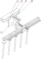
Fig. 1 is a schematic perspective view of the present invention.
Fig. 2 is a partial perspective view of the first embodiment of the present invention.
Fig. 3 is a partial perspective view of the second embodiment of the present invention.
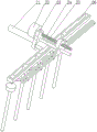
Fig. 4 is a schematic view of a partial three-dimensional structure of the present invention.
Fig. 5 is a partial perspective view illustrating a fourth embodiment of the present invention.
Fig. 6 is a schematic partial perspective view of the present invention.
Fig. 7 is a schematic diagram of a partial three-dimensional structure according to the present invention.
Fig. 8 is a schematic partial perspective view illustrating a seventh embodiment of the present invention.
Fig. 9 is a schematic perspective view of the present invention.
In the figure: 1. a supporting plate, 2, a first motor, 3, a first screw rod, 4, a second motor, 5, a first square block, 6, a vertical plate, 7, a cross rod, 8, a first round rod, 9, a guide rod, 10, a wheel, 11, a round shaft, 12, an L-shaped rod, 13, a U-shaped clamping block, 14, a square rod, 15, a sliding block, 16, a second round rod, 17, a U plate, 18, a second square block, 19, a track rod, 20, a third round rod, 21, a fourth round rod, 22, a third motor, 23, a fixing block, 24, a second screw rod, 25, a fifth round rod, 26, a trapezoidal sliding groove, 27, a sliding groove, 28, a sixth round rod, 29, a round block, 30, a semicircular plate, 32, a connecting rod, 33, a trapezoidal block, 34, a seventh round rod, 35, a first electric push rod, 36, a scriber, 37, a first square plate, 361, a supporting round rod, 362, a second electric push rod, 363, a second square plate, 364, a spring, a small plate, a vertical rod 365, a square plate, a, 369. semicircle block, 370, arc plate, 371, pole eight.
Detailed Description
An embodiment of the present invention will be described in detail below with reference to the accompanying drawings, but it should be understood that the scope of the present invention is not limited to the embodiment.
As shown in fig. 1-9, the invention includes symmetrical support plates 1, one of the support plates 1 is fixedly connected with a symmetrical motor one 2, output shafts of the symmetrical motor one 2 are respectively fixedly connected with one end of a screw rod one 3, the other end of the symmetrical screw rod one 3 is respectively connected with another support plate 1 through a bearing, the symmetrical screw rod one 3 is respectively connected with a square 5 through a screw thread, the square 5 is fixedly connected with a symmetrical vertical plate 6, the symmetrical vertical plate 6 is respectively and fixedly connected with a cross rod 7, the cross rod 7 is fixedly connected with a round rod two 16, the cross rod 7 is fixedly connected with a symmetrical round rod one 8, the symmetrical round rod one 8 is respectively and fixedly connected with a guide rod 9, and the square 5 is fixedly connected with a scribing mechanism.
The scribing mechanism comprises a second motor 4, the square 5 is fixedly connected with the second motor 4, an output shaft of the second motor 4 is fixedly connected with a round shaft 11, the round shaft 11 is fixedly connected with an L-shaped rod 12, and a round rod bearing of the L-shaped rod 12 is connected with a U-shaped clamping block 13.
The round bar II 16 is hinged to one end of the square bar 14, the U-shaped fixture block 13 is matched with the square bar 14, the square bar 14 is hinged to the round bar III 20, the round bar III 20 is fixedly connected with the slider 15, the slider 15 is arranged in a track of the track bar 19, the track bar 19 is fixedly connected with the square block II 18, the square block II 18 is fixedly connected with the U plate 17, the guide rod 9 penetrates through the square block II 18, and the guide rod 9 is arranged in the U plate 17.
The U plate 17 is fixedly connected with a first square plate 37, the first square plate 37 is fixedly connected with one end of a fourth round rod 21, the other end of the fourth round rod 21 is fixedly connected with a fixed block 23, the fixed block 23 is fixedly connected with a third motor 22, an output shaft of the third motor 22 penetrates through the fixed block 23, an output shaft of the third motor 22 is fixedly connected with a second screw 24, the fixed block 23 is fixedly connected with a fifth round rod 25, the fixed block 23 is fixedly connected with a trapezoidal sliding chute 26, the second screw 24 is in threaded connection with a round block 29, the round block 29 is fixedly connected with a semicircular plate 30, the fifth round rod 25 penetrates through the semicircular plate 30, the semicircular plate 30 is fixedly connected with a sliding chute 27, a group of uniformly distributed six round rods 28 is arranged in the sliding chute 27, each six round rod 28 is respectively hinged with one end of two adjacent connecting rods 32, and the other end of each connecting rod 32 is respectively hinged with a corresponding seven, a group of uniformly distributed trapezoidal blocks 33 are arranged in the trapezoidal sliding groove 26, the trapezoidal sliding groove 26 is fixedly connected with one trapezoidal block 33 at the end part, each round rod seven 34 is fixedly connected with the corresponding trapezoidal block 33, and each round rod seven 34 is fixedly connected with a first electric push rod 35.
The push rod end of each electric push rod I35 is fixedly connected with a scriber 36.
The scriber 36 is a scribing rod, and the push rod end of the first electric push rod 35 is fixedly connected with the scribing rod.
The scriber 36 is a replaceable scribing device, the scribing device comprises a supporting round rod 361, a push rod end of a first electric push rod 35 is fixedly connected with the supporting round rod 361, the supporting round rod 361 is fixedly connected with a second electric push rod 362, a push rod end of the second electric push rod 362 is fixedly connected with a second square plate 363, the second square plate 363 is fixedly connected with symmetrical vertical rods 367, the symmetrical vertical rods 367 are respectively and fixedly connected with a round rod eight 371, the supporting round rod 361 is fixedly connected with a small square plate 365, the second square plate 363 is fixedly connected with the small square plate 365 through a spring 364, the supporting round rod 361 is hinged with symmetrical sliding groove rods 369, the symmetrical round rods 371 eight are respectively arranged in sliding grooves of the corresponding sliding groove rods 366, the symmetrical sliding groove rods 366 are respectively and fixedly connected with a connecting rod 368, the symmetrical connecting rods 368 are respectively and fixedly connected with semicircular blocks, the supporting round rod 361 is fixedly connected with an arc-shaped plate 370, the symmetrical semicircular blocks 369 match the arcuate plate 370.
The symmetrical supporting plates 1 are respectively hinged with a group of uniformly distributed wheels 10.
The spring 364 provides some cushioning.
The electric push rod I1, the electric push rod II 4, the electric push rod III 14, the steering engine I8, the steering engine II 21 and the motor 11 are respectively electrically connected with a controller.
The number of the trapezoidal blocks 33 of one set is one more than the number of the round bars 28 of one set.
The motor I2, the motor II 4, the motor III 22, the electric push rod I35 and the electric push rod II 362 are respectively electrically connected with a controller.
The working process of the invention is as follows:
and (3) early-stage debugging is carried out on the controller, so that the controller controls the switching time of the motor I2, the motor II 4, the motor III 22, the electric push rod I35 and the electric push rod II 362, and straight lines, curved lines and bending lines are drawn on the cement floor which is not dry.
The first embodiment is as follows: the scriber 36 adopts a scriber rod, when the distance between adjacent anti-skid threads is adjusted firstly, the distance between the threads is set on the controller, the controller opens the third motor 22, the third motor 22 drives the second screw rod 24 to rotate, the second screw rod 24 drives the round block 29 to move, the round block 29 drives the semi-circular plate 30 to move along the fifth round rod 25, the semi-circular plate 30 drives the chute 27 to move, the chute 27 drives the sixth round rod 28 to move, the sixth round rod 28 drives the connecting rod 32 to swing, the connecting rod 32 drives the trapezoidal block 33 (except the trapezoidal block 33 at the end part) to move along the trapezoidal chute 26, the connecting rod 34 drives the seventh round rod 34 (except the seventh end round rod 34), the first electric push rod 35 (except the first end electric push rod 35) and the scriber 36 (except the scriber 36 at the end part), so as to adjust the distance between the scribers 36, and when the distance is.
The apparatus is moved into position so that the apparatus spans the green cement floor with the blocks one 5 in contact with or adjacent one of the support plates 1.
When the line is drawn, the controller opens the first electric push rod 35, the first electric push rod 35 drives the line drawing rod to move downwards for a proper distance, and the controller closes the first electric push rod 35. The controller controls the first motor 2 to rotate, the first motor 2 drives the first screw rod 3 to rotate, the first screw rod 3 drives the first square 5, the vertical plate 6, the cross rod 7, the first round rod 8, the guide rod 9 and the second round rod 16 to move, and the first square 5 drives the scribing mechanism to move. The marking rod of the marking mechanism contacts the cement ground to mark a straight line on the cement ground.
When the line is marked with a broken line, the controller controls the first motor 2 to rotate for a certain number of turns (set according to the road width), the first line is marked, the controller turns off the first motor 2, then the controller controls the second motor 4 to rotate (the number of turns is less than one), the second motor 4 drives the circular shaft 11 to rotate, the circular shaft 11 drives the L-shaped rod 12 to swing, the L-shaped rod 12 drives the U-shaped fixture block 13 to swing, the U-shaped fixture block 13 drives the square rod 14 to swing, the square rod 14 drives the circular rod three 20 to move, the circular rod three 20 drives the slide block 15 to move along the track of the track rod 19, the slide block 15 drives the track rod 19 to move, the track rod 19 drives the second block 18 to move along the guide rod 9, the second block 18 drives the U plate 17, the first square plate 37, the fourth rod 21, the third motor 22, the fixed block 23, the trapezoidal chute 26, the chute 27, the sixth rod 28, the circular block 29, the connecting rod 30, the connecting rod 32, the trapezoidal, the scriber 36 moves for a certain distance to enable the first section of line and the second section of line to deviate, then the motor II 4 is controlled to be turned off, the motor I2 is turned on by the controller, the motor I2 rotates for a certain number of turns (set according to actual conditions), then the electric push rod I35 is turned on by the controller, the scriber 36 scribes on the cement ground, and the two groups of anti-skid lines are distributed at intervals to form bending lines.
When drawing the curve, the controller control motor 2 and motor two 4 rotate simultaneously, according to the radian of curve, set up motor two 4's rotational speed, realize that scriber 36 removes along screw rod 3 direction and removes along the direction of guide bar 9 simultaneously, form the curve non-skid thread on the cement ground of not doing, realized drawing the curve of different density through different motor speed, the curve non-skid thread that motor two 4 rotational speeds were drawn sooner is denser.
Example two: when the scriber 36 adopts a replaceable scribing device, the control mode of the controller is the same as that of the first embodiment when straight lines, bent lines and curves are scribed. Compared with the first embodiment, the second embodiment can realize the adjustment of the line width, the controller controls the second electric push rod 362, the second electric push rod 362 drives the second square plate 363 to move, the second square plate 363 stretches or compresses the spring 364, the second square plate 363 drives the vertical rod 367 to move, the vertical rod 367 drives the eight circular rod 371 to move and simultaneously move along the sliding groove of the sliding groove rod 366, the eight circular rod 371 drives the sliding groove rod 366 to swing, the sliding groove rod 366 drives the connecting rod 368 and the semicircular block 369 to move, so that the semicircular block 369 is in contact with or far away from the arc-shaped plate 370, when the semicircular block 369 is far away from the arc-shaped plate 370, the line width of the scribing line is narrow, and when the semicircular block 369 is in contact with the arc-shaped plate 370.
The above disclosure is only for the specific embodiment of the present invention, but the present invention is not limited thereto, and any variations that can be made by those skilled in the art should fall within the scope of the present invention.
Claims (8)
1. A road surface marker comprising symmetrical support plates (1), characterized in that:
the support plate (1) is fixedly connected with a symmetrical motor I (2);
output shafts of the symmetrical first motors (2) are respectively and fixedly connected with one end of the first screw (3);
the other ends of the symmetrical first screw rods (3) are respectively in bearing connection with the other supporting plate (1);
the symmetrical first screw rods (3) are respectively in threaded connection with the square blocks (5);
the square blocks (5) are fixedly connected with symmetrical vertical plates (6);
the symmetrical vertical plates (6) are respectively and fixedly connected with a cross rod (7);
the cross rod (7) is fixedly connected with a second round rod (16);
the cross rod (7) is fixedly connected with symmetrical first round rods (8);
the symmetrical first round rods (8) are respectively and fixedly connected with guide rods (9);
the square block (5) is fixedly connected with a marking mechanism.
2. The road surface marker as claimed in claim 1, wherein: the scribing mechanism comprises a second motor (4), the square block (5) is fixedly connected with the second motor (4), an output shaft of the second motor (4) is fixedly connected with a round shaft (11), the round shaft (11) is fixedly connected with an L-shaped rod (12), and a round rod bearing of the L-shaped rod (12) is connected with a U-shaped clamping block (13).
3. The road surface marker as claimed in claim 2, wherein: round bar two (16) hinge joint square pole (14) one end, U-shaped fixture block (13) match square pole (14), square pole (14) hinge joint round pole three (20), round bar three (20) fixed connection slider (15), slider (15) set up in the track of track pole (19), track pole (19) fixed connection square two (18), square two (18) fixed connection U board (17), guide bar (9) are passed square two (18), guide bar (9) set up in U board (17).
4. The road surface marker as claimed in claim 3, wherein: the U plate (17) is fixedly connected with a square plate I (37), the square plate I (37) is fixedly connected with one end of a round rod IV (21), the other end of the round rod IV (21) is fixedly connected with a fixed block (23), the fixed block (23) is fixedly connected with a motor III (22), an output shaft of the motor III (22) penetrates through the fixed block (23), an output shaft of the motor III (22) is fixedly connected with a screw rod II (24), the fixed block (23) is fixedly connected with a round rod V (25), the fixed block (23) is fixedly connected with a trapezoidal sliding groove (26), the screw rod II (24) is in threaded connection with a round block (29), the round block (29) is fixedly connected with a semicircular plate (30), the round rod V (25) penetrates through the semicircular plate (30), the semicircular plate (30) is fixedly connected with a sliding groove (27), a set of uniformly distributed round rods six (28) is arranged in the sliding groove (27, each six round rods (28) are respectively hinged to one end of each two adjacent connecting rods (32), the other end of each connecting rod (32) is respectively hinged to the corresponding seven round rods (34), a group of uniformly distributed trapezoidal blocks (33) are arranged in each trapezoidal sliding groove (26), each trapezoidal sliding groove (26) is fixedly connected with one trapezoidal block (33) at the end, each seven round rods (34) are respectively and fixedly connected with the corresponding trapezoidal block (33), and each seven round rods (34) are respectively and fixedly connected with the corresponding one electric push rod (35).
5. The road surface marker as claimed in claim 4, wherein: the push rod end of each electric push rod I (35) is fixedly connected with a scriber (36) respectively.
6. The road surface marker as claimed in claim 5, wherein: the scriber (36) is a scribing rod, and the push rod end of the electric push rod I (35) is fixedly connected with the scribing rod.
7. The road surface marker as claimed in claim 5, wherein: the scriber (36) is a replaceable scribing device, the scribing device comprises a supporting round rod (361), a push rod end of a first electric push rod (35) is fixedly connected with the supporting round rod (361), the supporting round rod (361) is fixedly connected with a second electric push rod (362), a push rod end of the second electric push rod (362) is fixedly connected with a second square plate (363), the second square plate (363) is fixedly connected with symmetrical vertical rods (367), the symmetrical vertical rods (367) are respectively and fixedly connected with eight round rods (371), the supporting round rod (361) is fixedly connected with a small square plate (365), the second square plate (363) is fixedly connected with the small square plate (365) through a spring (364), the supporting round rod (361) is connected with symmetrical chute rods (366), the eight round rods (371) are respectively arranged in sliding grooves of the corresponding chute rods (366), and the symmetrical chute rods (366) are respectively and fixedly connected with connecting rods (368), the symmetrical connecting rods (368) are respectively fixedly connected with semicircular blocks (369), the supporting circular rods (361) are fixedly connected with an arc-shaped plate (370), and the symmetrical semicircular blocks (369) are matched with the arc-shaped plate (370).
8. The road surface marker as claimed in claim 1, wherein: the symmetrical supporting plates (1) are respectively hinged with a group of uniformly distributed wheels (10).
Priority Applications (1)
| Application Number | Priority Date | Filing Date | Title |
|---|---|---|---|
| CN202010445504.XA CN111663409A (en) | 2020-05-24 | 2020-05-24 | Road surface scriber |
Applications Claiming Priority (1)
| Application Number | Priority Date | Filing Date | Title |
|---|---|---|---|
| CN202010445504.XA CN111663409A (en) | 2020-05-24 | 2020-05-24 | Road surface scriber |
Publications (1)
| Publication Number | Publication Date |
|---|---|
| CN111663409A true CN111663409A (en) | 2020-09-15 |
Family
ID=72384381
Family Applications (1)
| Application Number | Title | Priority Date | Filing Date |
|---|---|---|---|
| CN202010445504.XA Withdrawn CN111663409A (en) | 2020-05-24 | 2020-05-24 | Road surface scriber |
Country Status (1)
| Country | Link |
|---|---|
| CN (1) | CN111663409A (en) |
Cited By (2)
| Publication number | Priority date | Publication date | Assignee | Title |
|---|---|---|---|---|
| CN112227153A (en) * | 2020-09-21 | 2021-01-15 | 曾龙 | Cement road surface scratch device |
| CN113355982A (en) * | 2021-03-10 | 2021-09-07 | 广东辰集建设工程有限公司 | Auxiliary indentation equipment for concrete construction pouring and rapid indentation method thereof |
Citations (4)
| Publication number | Priority date | Publication date | Assignee | Title |
|---|---|---|---|---|
| US4318631A (en) * | 1980-01-21 | 1982-03-09 | Vickers Richard R | Texturing broom apparatus for roadway pavements |
| CN2450257Y (en) * | 2000-11-17 | 2001-09-26 | 广东宝丽华建设工程公司 | Highway concrete pavement roughening machine by picking |
| CN2575142Y (en) * | 2002-10-08 | 2003-09-24 | 陈天明 | Multifunction road-repairing cart |
| CN209323322U (en) * | 2019-01-11 | 2019-08-30 | 徐涛 | A kind of road construction road surface texturizing equipment |
-
2020
- 2020-05-24 CN CN202010445504.XA patent/CN111663409A/en not_active Withdrawn
Patent Citations (4)
| Publication number | Priority date | Publication date | Assignee | Title |
|---|---|---|---|---|
| US4318631A (en) * | 1980-01-21 | 1982-03-09 | Vickers Richard R | Texturing broom apparatus for roadway pavements |
| CN2450257Y (en) * | 2000-11-17 | 2001-09-26 | 广东宝丽华建设工程公司 | Highway concrete pavement roughening machine by picking |
| CN2575142Y (en) * | 2002-10-08 | 2003-09-24 | 陈天明 | Multifunction road-repairing cart |
| CN209323322U (en) * | 2019-01-11 | 2019-08-30 | 徐涛 | A kind of road construction road surface texturizing equipment |
Cited By (2)
| Publication number | Priority date | Publication date | Assignee | Title |
|---|---|---|---|---|
| CN112227153A (en) * | 2020-09-21 | 2021-01-15 | 曾龙 | Cement road surface scratch device |
| CN113355982A (en) * | 2021-03-10 | 2021-09-07 | 广东辰集建设工程有限公司 | Auxiliary indentation equipment for concrete construction pouring and rapid indentation method thereof |
Similar Documents
| Publication | Publication Date | Title |
|---|---|---|
| US4131103A (en) | Apparatus for sawing stone | |
| CN111663409A (en) | Road surface scriber | |
| EP3486052A1 (en) | Pattern forming method for quartz surface and pattern forming device for quartz surface | |
| US20050066955A1 (en) | Facing machine for hard-fired ceramic tiles | |
| KR100780996B1 (en) | Stone Circular Cutting Machine | |
| CN102773932A (en) | Rocking multiwire cutting machine | |
| CN111015960A (en) | Method for processing artificial natural stone lath | |
| CN206359817U (en) | A kind of cutter device with elevating function | |
| US3683762A (en) | Apparatus for making a rigid road which has a textured surface | |
| CN110883627A (en) | Stone surface grinding device | |
| CN206748760U (en) | A kind of building reinforced concrete ground cutter | |
| CN2581144Y (en) | Disc set saw | |
| CN202037703U (en) | Ceramic tile blank polishing and grinding equipment with natural wind and sand eroding effect | |
| CN202742415U (en) | Swinging multi-wire cutting machine | |
| CN111251105A (en) | Intelligent polishing and grinding machine comprising multiple polishing wheels | |
| CN213766559U (en) | Stone cutting equipment | |
| CN111168777A (en) | Chopstick trimming equipment | |
| CN2756425Y (en) | Chain conveyer type automatic brick cutter | |
| CN206999231U (en) | A kind of on-plane surface mold screeding device | |
| CN212601079U (en) | Steel bar cutting device for building engineering | |
| CN220284557U (en) | Concrete pavement grooving device | |
| CN110900344A (en) | Stone surface treatment system | |
| CN214520159U (en) | Shaft outer edge surface marking device | |
| CN207757884U (en) | A kind of artificial quartz stone plate cutting equipment | |
| US2271905A (en) | Method of and device for cutting stone and other materials |
Legal Events
| Date | Code | Title | Description |
|---|---|---|---|
| PB01 | Publication | ||
| PB01 | Publication | ||
| SE01 | Entry into force of request for substantive examination | ||
| SE01 | Entry into force of request for substantive examination | ||
| WW01 | Invention patent application withdrawn after publication |
Application publication date: 20200915 |
|
| WW01 | Invention patent application withdrawn after publication |