CN111663299A - Variable Damping Shock Absorbers and Clothes Treatment Equipment - Google Patents
Variable Damping Shock Absorbers and Clothes Treatment Equipment Download PDFInfo
- Publication number
- CN111663299A CN111663299A CN201910169330.6A CN201910169330A CN111663299A CN 111663299 A CN111663299 A CN 111663299A CN 201910169330 A CN201910169330 A CN 201910169330A CN 111663299 A CN111663299 A CN 111663299A
- Authority
- CN
- China
- Prior art keywords
- damping
- ring
- shock absorber
- reducing groove
- damping ring
- Prior art date
- Legal status (The legal status is an assumption and is not a legal conclusion. Google has not performed a legal analysis and makes no representation as to the accuracy of the status listed.)
- Granted
Links
Images


Classifications
-
- D—TEXTILES; PAPER
- D06—TREATMENT OF TEXTILES OR THE LIKE; LAUNDERING; FLEXIBLE MATERIALS NOT OTHERWISE PROVIDED FOR
- D06F—LAUNDERING, DRYING, IRONING, PRESSING OR FOLDING TEXTILE ARTICLES
- D06F37/00—Details specific to washing machines covered by groups D06F21/00 - D06F25/00
- D06F37/20—Mountings, e.g. resilient mountings, for the rotary receptacle, motor, tub or casing; Preventing or damping vibrations
Landscapes
- Engineering & Computer Science (AREA)
- Textile Engineering (AREA)
- Fluid-Damping Devices (AREA)
Abstract
本发明属于阻尼减震装置的领域,具体提供一种变阻尼减震器和衣物处理设备。本发明旨在解决现有的变阻尼减震器的阻尼件容易变形失效的问题。为此,本发明的变阻尼减震器包括套筒、柱塞和阻尼环。其中,柱塞上设置有环形的第一变径槽和储油槽,柱塞沿轴向可滑动地插入套筒中,使得第一变径槽始终位于套筒内。阻尼环套设在第一变径槽内,并且阻尼环的外侧端与套筒的内壁相抵。阻尼环上设置有开口,阻尼环通过改变开口的大小能够改变径向上的尺寸,进而能够匹配第一变径槽的直径。因此,本发明的阻尼环相对于现有技术中的阻尼环,有效地避免了阻尼环在沿径向被长久地挤压时,厚度上发生的不可逆转的形变,保证了减震器的可靠性。
The invention belongs to the field of damping and shock absorption devices, and in particular provides a variable damping shock absorber and clothing processing equipment. The invention aims to solve the problem that the damping member of the existing variable damping shock absorber is easy to deform and fail. To this end, the variable damping shock absorber of the present invention includes a sleeve, a plunger and a damping ring. The plunger is provided with an annular first reducing groove and an oil storage groove, and the plunger is slidably inserted into the sleeve along the axial direction, so that the first reducing groove is always located in the sleeve. The damping ring is sleeved in the first reducing groove, and the outer end of the damping ring is in contact with the inner wall of the sleeve. The damping ring is provided with an opening, and the damping ring can change the size in the radial direction by changing the size of the opening, and then can match the diameter of the first reducing groove. Therefore, compared with the damping ring in the prior art, the damping ring of the present invention effectively avoids the irreversible deformation in the thickness of the damping ring when the damping ring is pressed for a long time in the radial direction, and ensures the reliability of the shock absorber. sex.
Description
技术领域technical field
本发明属于阻尼减震装置的领域,具体提供一种变阻尼减震器和衣物处理设备。The invention belongs to the field of damping and shock absorption devices, and in particular provides a variable damping shock absorber and clothing processing equipment.
背景技术Background technique
现有的滚筒洗衣机主要包括箱体、外筒和内筒。其中,外筒通过挂簧和减震器与箱体固定连接。具体地,外筒的顶部通过挂簧与箱体的顶部固定连接,外筒的底部通过减震器与箱体的底部固定连接。内筒可转动地设置在外筒中。The existing drum washing machine mainly includes a box body, an outer tub and an inner tub. Wherein, the outer cylinder is fixedly connected with the box body through the hanging spring and the shock absorber. Specifically, the top of the outer cylinder is fixedly connected to the top of the box body through the hanging spring, and the bottom of the outer cylinder is fixedly connected to the bottom of the box body through the shock absorber. The inner cylinder is rotatably provided in the outer cylinder.
洗衣机在工作的过程中,由于衣物在内筒中不均匀的分布,使得内筒在转动时会带动外筒一起上下、左右晃动。挂簧和减震器的设置能够降低外筒的晃动强度和幅度。尤其是减振器能够吸收并消除洗衣机的振动,防止洗衣机爬行,降低洗衣机噪音,进而保证了洗衣机性能,延长了洗衣机寿命。During the working process of the washing machine, due to the uneven distribution of the clothes in the inner drum, the inner drum will drive the outer drum to shake up and down, left and right together when the inner drum rotates. The setting of the hanging spring and the shock absorber can reduce the shaking intensity and amplitude of the outer cylinder. In particular, the shock absorber can absorb and eliminate the vibration of the washing machine, prevent the washing machine from crawling, and reduce the noise of the washing machine, thereby ensuring the performance of the washing machine and prolonging the life of the washing machine.
但是,现有技术中的减震器产生的阻尼力通常是一个恒定不变的值,不能适应洗衣机的所有工况。当洗衣机进行高速脱水时,外筒所能产生的振幅较小,需要的阻尼力也小;当洗衣机进行洗涤、漂洗、低速脱水时,外筒所能产生的振幅较大,需要的阻尼力也大。However, the damping force generated by the shock absorber in the prior art is usually a constant value, which cannot adapt to all working conditions of the washing machine. When the washing machine is performing high-speed dehydration, the outer cylinder can generate a small amplitude and the required damping force is also small; when the washing machine is performing washing, rinsing, and low-speed dehydration, the outer cylinder can generate a large amplitude and requires a large damping force.
为此,公开号为CN1519418A的专利文献中公开了一种减震器,其包括圆筒、插入所述圆筒内的活塞杆和套设在所述活塞杆上的可动阻尼件。其中,活塞杆上设置有用于安装可动阻尼件的环形槽,该环形槽的直径从中间向两侧逐渐增大。当可动阻尼件位于所述环形槽的中间位置时,可动阻尼件与圆筒之间的阻尼力较小,用于消除洗衣机高速脱水时产生的震动;当可动阻尼件位于所述环形槽的两侧位置时,可动阻尼件与圆筒之间的阻尼力较大,用于消除洗衣机洗涤、漂洗、低速脱水时产生的震动。To this end, a patent document with publication number CN1519418A discloses a shock absorber, which includes a cylinder, a piston rod inserted into the cylinder, and a movable damping member sleeved on the piston rod. Wherein, the piston rod is provided with an annular groove for installing the movable damping member, and the diameter of the annular groove gradually increases from the middle to both sides. When the movable damping member is located in the middle position of the annular groove, the damping force between the movable damping member and the cylinder is small, which is used to eliminate the vibration generated when the washing machine is dewatered at high speed; when the movable damping member is located in the annular groove When the two sides of the tank are located, the damping force between the movable damping member and the cylinder is relatively large, which is used to eliminate the vibration generated during washing, rinsing, and low-speed dehydration of the washing machine.
但是公开号为CN1519418A的专利文献中公开的减震器在长久的使用过程中,可动阻尼件容易被所述环形槽的两端撑变形,进而不能够与所述环形槽的中间位置相匹配,使减震器在洗衣机高速脱水时失去阻尼效力,进而使洗衣机的噪音较大。However, during the long-term use of the shock absorber disclosed in the patent document with publication number CN1519418A, the movable damping member is easily deformed by the two ends of the annular groove, so that it cannot match the middle position of the annular groove. , so that the shock absorber loses its damping effect when the washing machine is dehydrated at high speed, which in turn makes the washing machine noisy.
相应地,本领域需要一种新的变阻尼减震器来解决上述问题。Accordingly, there is a need in the art for a new variable damping shock absorber to solve the above problems.
发明内容SUMMARY OF THE INVENTION
为了解决现有技术中的上述问题,即为了解决现有的变阻尼减震器的阻尼件容易变形失效的问题,本发明提供了一种变阻尼减震器,所述变阻尼减震器包括套筒、柱塞和阻尼环;所述柱塞上设置有环形的第一变径槽和位于所述第一变径槽两侧的储油槽,所述柱塞沿轴向可滑动地插入所述套筒中,使得所述第一变径槽和所述储油槽始终位于所述套筒内;所述阻尼环套设在所述第一变径槽内,并且所述阻尼环的外侧端与所述套筒的内壁相抵;所述阻尼环设置成能够沿径向产生形变,以便使所述阻尼环的内侧端的直径匹配所述第一变径槽的直径。In order to solve the above problem in the prior art, that is, to solve the problem that the damping member of the existing variable damping shock absorber is easy to deform and fail, the present invention provides a variable damping shock absorber, the variable damping shock absorber comprises: A sleeve, a plunger and a damping ring; the plunger is provided with an annular first reducing groove and oil storage grooves located on both sides of the first reducing groove, and the plunger is slidably inserted into the In the sleeve, the first reducing groove and the oil storage groove are always located in the sleeve; the damping ring is sleeved in the first reducing groove, and the outer end of the damping ring is abutting against the inner wall of the sleeve; the damping ring is arranged to be deformable in the radial direction, so that the diameter of the inner end of the damping ring matches the diameter of the first reducing groove.
在上述变阻尼减震器的优选技术方案中,所述阻尼环上设置有开口,所述阻尼环能够随着所述开口变大而沿径向变大以及随着所述开口变小而沿径向变小。In the preferred technical solution of the above variable damping shock absorber, the damping ring is provided with an opening, and the damping ring can increase in radial direction as the opening becomes larger, and can increase along the radial direction as the opening becomes smaller. radially smaller.
在上述变阻尼减震器的优选技术方案中,所述阻尼环包括固定连接或一体制成的内摩擦环和外摩擦环,所述内摩擦环与所述柱塞滑动连接,所述外摩擦环与所述套筒滑动连接;所述开口包括形成在所述内摩擦环上的第一开口和形成在所述外摩擦环上的第二开口,所述第一开口使所述内摩擦环形成开口环,所述第二开口使所述外摩擦环形成开口环。In the preferred technical solution of the above variable damping shock absorber, the damping ring includes an inner friction ring and an outer friction ring that are fixedly connected or integrally made, the inner friction ring is slidingly connected to the plunger, and the outer friction ring is slidably connected to the plunger. A ring is slidably connected to the sleeve; the opening includes a first opening formed on the inner friction ring and a second opening formed on the outer friction ring, the first opening allowing the inner friction ring A split ring is formed, and the second opening causes the outer friction ring to form a split ring.
在上述变阻尼减震器的优选技术方案中,所述内摩擦环的两端沿径向设置有多个第一凸起结构,所述外摩擦环的两端沿轴向设置有多个第二凸起结构,所述第一凸起结构和所述第二凸起结构彼此咬合,并且所述第二凸起结构沿轴向伸出所述第一凸起结构。In the preferred technical solution of the above variable damping shock absorber, the two ends of the inner friction ring are provided with a plurality of first convex structures in the radial direction, and the two ends of the outer friction ring are provided with a plurality of first convex structures in the axial direction. Two protruding structures, the first protruding structure and the second protruding structure are engaged with each other, and the second protruding structure protrudes from the first protruding structure in the axial direction.
在上述变阻尼减震器的优选技术方案中,所述多个第一凸起结构和所述多个第二凸起结构分别绕所述阻尼环的周向等间距分布。In the preferred technical solution of the variable damping shock absorber, the plurality of first protruding structures and the plurality of second protruding structures are respectively distributed at equal intervals around the circumference of the damping ring.
在上述变阻尼减震器的优选技术方案中,所述第一凸起结构和所述第二凸起结构沿所述阻尼环周向上的宽度相同。In the above preferred technical solution of the variable damping shock absorber, the widths of the first protruding structure and the second protruding structure along the circumferential direction of the damping ring are the same.
在上述变阻尼减震器的优选技术方案中,所述套筒的内壁上设置有环形的第二变径槽,所述第二变径槽的至少一部分与所述第一变径槽对准,并且所述阻尼环的外侧端始终与所述第二变径槽的底部相抵。In the preferred technical solution of the above variable damping shock absorber, an annular second diameter reduction groove is provided on the inner wall of the sleeve, and at least a part of the second diameter reduction groove is aligned with the first diameter reduction groove , and the outer end of the damping ring is always in contact with the bottom of the second reducing groove.
在上述变阻尼减震器的优选技术方案中,所述阻尼环采用弹性材料制成;并且/或者,所述第一变径槽的直径沿轴向从中间向两侧逐渐增大;并且/或者,所述第二变径槽的直径沿轴向从中间向两侧逐渐减小;并且/或者,所述第一变径槽和/或所述第二变径槽为对称结构。In the preferred technical solution of the variable damping shock absorber, the damping ring is made of elastic material; and/or the diameter of the first variable diameter groove gradually increases from the middle to both sides in the axial direction; and/or Alternatively, the diameter of the second diameter reducing groove gradually decreases from the middle to both sides in the axial direction; and/or, the first diameter reducing groove and/or the second diameter reducing groove are symmetrical structures.
此外,本发明还提供了一种衣物处理设备,所述衣物处理设备包括上述优选技术方案中任一项所述的变阻尼减震器。In addition, the present invention also provides a laundry treatment device, which includes the variable damping shock absorber according to any one of the above preferred technical solutions.
在上述衣物处理设备的优选技术方案中,所述衣物处理设备包括洗衣机、干衣机和洗干一体机中的至少一种。In a preferred technical solution of the above-mentioned clothes treating device, the clothes treating device includes at least one of a washing machine, a clothes dryer and an all-in-one washing and drying machine.
本领域技术人员能够理解的是,在本发明的优选技术方案中,通过在柱塞上设置环形的第一变径槽,并将阻尼环设置成能够沿径向产生形变,使得阻尼环的内侧端的直径能够根据第一变径槽的直径变化而变化。因此,本发明沿径向可形变的阻尼环不仅能够适应第一变径槽的直径变化,而且相对于传统的沿径向不能够发生形变的阻尼环来说,有效地提高了减震器的可靠性,以及提高了使用寿命。Those skilled in the art can understand that, in the preferred technical solution of the present invention, by arranging an annular first reducing groove on the plunger, and arranging the damping ring to be able to deform in the radial direction, the inner side of the damping ring The diameter of the end can vary according to the diameter of the first reducing groove. Therefore, the radially deformable damping ring of the present invention can not only adapt to the diameter change of the first reducing groove, but also effectively improves the damping effect of the shock absorber compared with the traditional damping ring which cannot be deformed in the radial direction. reliability, and improved service life.
本领域技术人员能够理解的是,当阻尼环位于第一变径槽内直径较小的位置时,阻尼环对套筒的压力较小,两者之间所能产生的阻尼力也较小;当阻尼环位于第一变径槽内直径较大的位置时,阻尼环对套筒的压力较大,两者之间所能产生的阻尼力也较大。Those skilled in the art can understand that when the damping ring is located at a position with a smaller diameter in the first reducing groove, the pressure of the damping ring on the sleeve is smaller, and the damping force that can be generated between the two is also smaller; when When the damping ring is located at a position with a larger diameter in the first reducing groove, the pressure of the damping ring on the sleeve is relatively large, and the damping force that can be generated between the two is also relatively large.
此外,本发明还通过在柱塞上第一变径槽的两侧设置储油槽,使得储油槽内的润滑油能够在柱塞移动的过程中对阻尼环进行润滑,减少了阻尼环的磨损,提高了阻尼环的使用寿命。In addition, the present invention also provides oil storage grooves on both sides of the first reducing groove on the plunger, so that the lubricating oil in the oil storage groove can lubricate the damping ring during the movement of the plunger, thereby reducing the wear of the damping ring. The service life of the damping ring is improved.
进一步,本发明的阻尼环上设置有开口,当所述阻尼环沿径向变大时,所述开口变大;当所述阻尼环沿径向变小时,所述开口变小。换句话说,本发明的阻尼环能够通过改变其上开口的大小来实现径向上的形变。因此,本发明的阻尼环相对于现有技术中的阻尼环,有效地避免了阻尼环在沿径向被长久地挤压时,厚度上发生的不可逆转的形变,保证了减震器的可靠性。Further, the damping ring of the present invention is provided with an opening. When the damping ring becomes larger in the radial direction, the opening becomes larger; when the damping ring becomes smaller in the radial direction, the opening becomes smaller. In other words, the damping ring of the present invention can achieve radial deformation by changing the size of its upper opening. Therefore, compared with the damping ring in the prior art, the damping ring of the present invention effectively avoids the irreversible deformation in the thickness of the damping ring when the damping ring is pressed for a long time in the radial direction, and ensures the reliability of the shock absorber. sex.
进一步优选地,所述阻尼环包括与所述柱塞滑动连接内摩擦环和与所述套筒滑动连接的外摩擦环,所述内摩擦环的两端沿径向设置有多个第一凸起结构,所述外摩擦环的两端沿轴向设置有多个第二凸起结构,所述第一凸起结构和所述第二凸起结构彼此咬合在一起,并且所述第二凸起结构沿轴向伸出所述第一凸起结构。当阻尼环滑动到所述第一变径槽的末端时能够先通过第二凸起结构与第一变径槽的侧壁发生接触,避免了噪音的发生,优化了用户的使用体验。其中,所述阻尼环采用弹性材料制成,以便减少噪声的发生。Further preferably, the damping ring includes an inner friction ring slidably connected with the plunger and an outer friction ring slidably connected with the sleeve, and two ends of the inner friction ring are radially provided with a plurality of first protrusions. The two ends of the outer friction ring are provided with a plurality of second convex structures along the axial direction, the first convex structures and the second convex structures are engaged with each other, and the second convex structures are The lifting structure protrudes from the first protruding structure in the axial direction. When the damping ring slides to the end of the first diameter reducing groove, it can first contact the side wall of the first reducing diameter groove through the second protruding structure, which avoids the occurrence of noise and optimizes the user experience. Wherein, the damping ring is made of elastic material, so as to reduce the occurrence of noise.
附图说明Description of drawings
下面参照附图来描述本发明的优选实施方式,附图中:Preferred embodiments of the present invention are described below with reference to the accompanying drawings, in which:
图1是本发明的变阻尼减震器在组装状态下的结构示意图;1 is a schematic structural diagram of the variable damping shock absorber of the present invention in an assembled state;
图2是本发明的变阻尼减震器在未组装时的结构示意图;2 is a schematic structural diagram of the variable damping shock absorber of the present invention when it is not assembled;
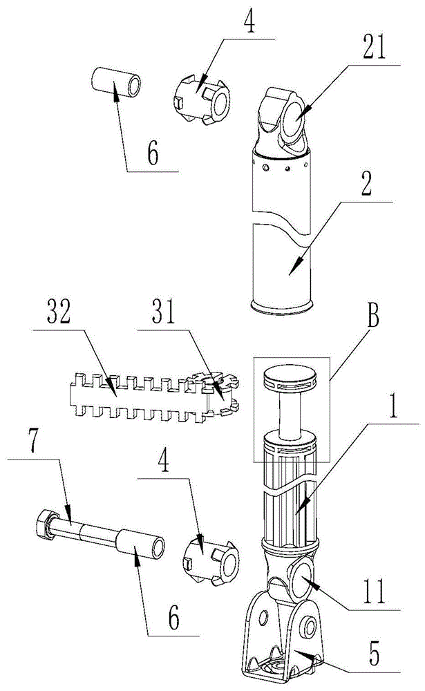
图3是本发明的变阻尼减震器的结构爆炸示意图;Fig. 3 is the structural exploded schematic diagram of the variable damping shock absorber of the present invention;
图4是图1中A部的放大图;Fig. 4 is the enlarged view of A part in Fig. 1;
图5是本发明的安装座的结构示意图;Fig. 5 is the structural representation of the mounting seat of the present invention;
图6是本发明的减震构件的结构示意图;6 is a schematic structural diagram of a shock absorbing member of the present invention;
图7是图3中B部的放大图;Fig. 7 is the enlarged view of B part in Fig. 3;
图8是本发明的变阻尼减震器的剖视图;8 is a cross-sectional view of the variable damping shock absorber of the present invention;
图9是图8中C部的放大图;Fig. 9 is the enlarged view of C part in Fig. 8;
图10是本发明的阻尼环的结构示意图;Fig. 10 is the structural representation of the damping ring of the present invention;
图11是本发明的外摩擦环的平面示意图。Figure 11 is a schematic plan view of the outer friction ring of the present invention.
附图标记列表:List of reference numbers:
1、柱塞;11、第一安装孔;12、第一变径槽;13、第一储油槽;14、第二储油槽;1. Plunger; 11. The first mounting hole; 12. The first reducing groove; 13. The first oil storage tank; 14. The second oil storage tank;
2、套筒;21、第二安装孔;22、第二变径槽;2. Sleeve; 21. Second mounting hole; 22. Second reducing groove;
3、阻尼环;31、内摩擦环;311、第一凸起结构;32、外摩擦环;321、第二凸起结构;3. Damping ring; 31. Inner friction ring; 311, First raised structure; 32, Outer friction ring; 321, Second raised structure;
4、减震构件;41、本体;42、第一凸起;43、第二凸起;4. Damping member; 41. Main body; 42. First protrusion; 43. Second protrusion;
5、安装座;51、底板;511、底部翻边孔;52、第一侧板;521、第一侧翻边孔;53、第二侧板;531、第二侧翻边孔;54、定位块;5. Mounting seat; 51, Bottom plate; 511, Bottom flanging hole; 52, First side plate; 521, First side flanging hole; 53, Second side plate; 531, Second side flanging hole; 54, positioning block;
6、管状构件;6. Tubular components;
7、螺栓。7. Bolts.
具体实施方式Detailed ways
本领域技术人员应当理解的是,本节实施方式仅仅用于解释本发明的技术原理,并非用于限制本发明的保护范围。例如,虽然本节实施例是以滚筒洗衣机为例来对本发明的变阻尼减震器进行介绍说明的,但是本发明的变阻尼减震器还可以应用到其他任意可行的设备上,例如汽车、摩托车、电动车、自行车等。本领域技术人员可以根据实际需要对其作出调整,以便适应具体的应用场合,调整后的技术方案仍将落入本发明的保护范围。It should be understood by those skilled in the art that the embodiments in this section are only used to explain the technical principles of the present invention, and are not used to limit the protection scope of the present invention. For example, although the embodiment of this section takes a drum washing machine as an example to describe the variable damping shock absorber of the present invention, the variable damping shock absorber of the present invention can also be applied to any other feasible equipment, such as automobiles, Motorcycles, electric vehicles, bicycles, etc. Those skilled in the art can adjust it according to actual needs so as to adapt to specific application occasions, and the adjusted technical solution will still fall within the protection scope of the present invention.
需要说明的是,在本发明的描述中,术语“中心”、“上”、“下”、“左”、“右”、“竖直”、“水平”、“内”、“外”等指示方向或位置关系的术语是基于附图所示的方向或位置关系,这仅仅是为了便于描述,而不是指示或暗示所述装置或元件必须具有特定的方位、以特定的方位构造和操作,因此不能理解为对本发明的限制。此外,术语“第一”、“第二”、“第三”仅用于描述目的,而不能理解为指示或暗示相对重要性。It should be noted that in the description of the present invention, the terms "center", "upper", "lower", "left", "right", "vertical", "horizontal", "inner", "outer", etc. Terms indicating a direction or positional relationship are based on the direction or positional relationship shown in the drawings, which are only for convenience of description, and do not indicate or imply that the device or element must have a particular orientation, be constructed and operate in a particular orientation, Therefore, it should not be construed as a limitation of the present invention. Furthermore, the terms "first", "second", and "third" are used for descriptive purposes only and should not be construed to indicate or imply relative importance.
此外,还需要说明的是,在本发明的描述中,除非另有明确的规定和限定,术语“安装”、“相连”、“连接”应做广义理解,例如,可以是固定连接,也可以是可拆卸连接,或一体地连接;可以是直接相连,也可以通过中间媒介间接相连,可以是两个元件内部的连通。对于本领域技术人员而言,可根据具体情况理解上述术语在本发明中的具体含义。In addition, it should also be noted that, in the description of the present invention, unless otherwise expressly specified and limited, the terms "installed", "connected" and "connected" should be understood in a broad sense, for example, it may be a fixed connection or a It is a detachable connection, or an integral connection; it can be directly connected, or indirectly connected through an intermediate medium, and it can be the internal communication of two components. For those skilled in the art, the specific meanings of the above terms in the present invention can be understood according to specific situations.
如图1至图3所示,本发明的变阻尼减震器主要包括柱塞1、套筒2和阻尼环3。其中,柱塞1沿轴向可滑动地插入套筒2中,阻尼环3沿径向设置在套筒2和柱塞1之间,并且阻尼环3的外侧端(外圆周面)与套筒2的内壁相抵,阻尼环3的内侧端(内圆周面)与柱塞1的外壁(外侧壁)相抵。柱塞1沿轴向相对于套筒2滑动时,阻尼环3能够产生阻尼力,阻碍柱塞1滑动。柱塞1远离套筒2的一端设置有第一安装孔11,套筒2远离柱塞1的一端设置有第二安装孔21。柱塞1和套筒2分别通过第一安装孔11和第二安装孔21与其它结构、装置或设备枢转连接。As shown in FIGS. 1 to 3 , the variable damping shock absorber of the present invention mainly includes a
如图2和图3所示,本发明的变阻尼减震器还包括减震构件4、安装座5、刚性的管状构件6和螺栓7。在安装好的状态下,第一安装孔11和第二安装孔21中分别卡置一个减震构件4,管状构件6插入减震构件4中,螺栓7穿过安装座5和管状构件6将安装座5与柱塞1和/或套筒2枢转地连接到一起。As shown in FIGS. 2 and 3 , the variable damping shock absorber of the present invention further includes a
如图4和图5所示,本发明的安装座5包括底板51、第一侧板52和第二侧板53。其中,底板51、第一侧板52和第二侧板53通过一块金属板折弯而成,并共同形成一个U形结构。此外,本领域技术人员还可以根据需要,通过任意可行的方式将底板51、第一侧板52和第二侧板53固定到一起,例如通过焊接的方式将底板51、第一侧板52和第二侧板53固定到一起,通过挤压成型的方式使底板51、第一侧板52和第二侧板53共同形成所述U形结构,通过铸造成型的方式将底板51、第一侧板52和第二侧板53铸造到一起。As shown in FIGS. 4 and 5 , the mounting
进一步,在本发明的优选实施方案中,所述金属板的厚度,即底板51、第一侧板52和第二侧板53的厚度都小于5mm,进一步优选地,底板51、第一侧板52和第二侧板53的厚度都等于1mm。或者,本领域技术人员也可以根据需要,将底板51和/或第一侧板52和/或第二侧板53设置成任意可行的厚度,例如将底板51的厚度设置成1mm、1.5mm、3mm等,将第一侧板52的厚度设置成1mm、1.5mm、3mm等,将第二侧板53的厚度设置成1mm、1.5mm、3mm等。其中,底板51、第一侧板52和第二侧板53的厚度既可以相同,也可以不同。Further, in a preferred embodiment of the present invention, the thickness of the metal plate, that is, the thicknesses of the
继续参阅图4和图5,安装座5包括翻边孔,该翻边孔又包括设置在底板51上的底部翻边孔511、设置在第一侧板52上的第一侧翻边孔521、设置在第二侧板53上的第二侧翻边孔531。其中,底部翻边孔511、第一侧翻边孔521和第二侧翻边孔531都是通过冲压工艺制成的,并且底部翻边孔51的翻边结构位于底板51靠近第一侧板52的一侧,第一侧翻边孔521的翻边结构位于第一侧板52远离第二侧板53的一侧,第二侧翻边孔531的翻边结构位于第二侧板53远离第一侧板52的一侧。即,底部翻边孔511沿着靠近第一侧板52的方向冲压而成,第一侧翻边孔521沿着远离第二侧板53的方向冲压形成,第二侧翻边孔531沿着远离第一侧板52冲压形成。Continuing to refer to FIGS. 4 and 5 , the mounting
虽然图中并未明确示出,但是在本发明的优选实施方案中,第一侧翻边孔521和第二侧翻边孔531中都设置有内螺纹,以便与螺栓7上的外螺纹相匹配。此外,本领域技术人员也可以根据需要,仅在第一侧翻边孔521和第二侧翻边孔531中的一个上设置内螺纹,并使该内螺纹与螺栓7上的外螺纹相匹配。进一步,本领域技术人员还可以根据需要,在底部翻边孔511上设置内螺纹。Although it is not clearly shown in the figure, in the preferred embodiment of the present invention, both the first
在本发明另一个可行的实施例中,本领域技术人员可以根据需要,在安装座5上仅设置底部翻边孔511、第一侧翻边孔521和第二侧翻边孔531中的一个或两个。In another feasible embodiment of the present invention, those skilled in the art may, as required, set only one of the
继续参阅图4和图5,底板51上还设置有定位块54,安装座5通过定位块54定位到诸如洗衣机的箱体的固定结构上。Continuing to refer to FIG. 4 and FIG. 5 , a
如图6所示,本发明的减震构件4包括筒状的本体41和与所述本体41固定连接或一体制成的凸起,所述凸起设置在本体41的轴向上的端部,所述凸起在本体41径向上的厚度沿本体41的轴向从所述端部向内逐渐增加。具体地,所述凸起包括设置在本体41的第一端上的第一凸起42和设置在本体41的第二端上的第二凸起43,并且第一凸起42的厚度从所述第一端向所述第二端逐渐增加,使得第一凸起42形成梯形凸起;第二凸起43的厚度从所述第二端向所述第一端逐渐增加,使得第二凸起43形成梯形凸起。As shown in FIG. 6 , the damping
继续参阅图6,第一凸起42和第二凸起43都是多个,并且多个第一凸起42和多个第二凸起43沿本体41的周向等间距设置。或者,本领域技术人员也可以根据需要,将多个第一凸起42和多个第二凸起43设置成非等间距分布的形式。Continuing to refer to FIG. 6 , both the
虽然图中并未明确示出,但是本发明的减震构件4由具有弹性的橡胶材料构成,以便提高减震构件4的减震性能,或者本领域技术人员也可以根据需要,将减震构件4采用任意可行的减震材料制成,例如塑料、泡沫、多孔金属等。Although it is not clearly shown in the figure, the damping
如图2和图3所示,在安装好的状态下,柱塞1上的减震构件4的本体41穿过第一安装孔11,第一凸起42和第二凸起43分别位于第一安装孔11的两端,并且第一凸起42和第二凸起43能够分别与第一安装孔11的两端抵接,防止减震构件4从第一安装孔11中脱出。套筒2上的减震构件4与柱塞1上的安装方式相同,此处不再做过多说明。As shown in FIG. 2 and FIG. 3 , in the installed state, the
此外,在本发明另一个可行的实施例中,本领域技术人员可以根据需要,在减震构件4上仅保留第一凸起42或第二凸起43,然后在减震构件4的另一端上设置止挡构件。安装时,减震构件4通过第一凸起42或第二凸起43插进第一安装孔11或第二安装孔21中,并通过止挡构件与第一安装孔11或第二安装孔21的端部抵接,防止减震构件4从第一安装孔11或第二安装孔21中脱出。其中,止挡构件可以是圆环、多个矩形凸起结构、多个半球形凸起结构等。In addition, in another feasible embodiment of the present invention, those skilled in the art may, as required, only retain the
如图3和图7所示,本发明的柱塞1在伸进套筒2的一端上设置有环形的第一变径槽12、第一储油槽13和第二储油槽14。其中,第一变径槽12用于安装阻尼环3,并且阻尼环3的内侧端始终与第一变径槽12的底部抵接。第一储油槽13和第二储油槽14分别位于第一变径槽12的两侧,用于容纳润滑油,为阻尼环3提供润滑,用于降低阻尼环3的摩擦损耗,延长阻尼环3的使用寿命。As shown in FIGS. 3 and 7 , the
如图8和图9所示,套筒2的内壁上设置有环形的第二变径槽22,阻尼环3的外侧端始终与第二变径槽22的底部相抵。在柱塞1移动的过程中,第二变径槽22的至少一部分与第一变径槽12对准,以便防止阻尼环3脱出第一变径槽12和/或第二变径槽22。As shown in FIG. 8 and FIG. 9 , the inner wall of the
虽然图中并未明确示出,但是在本发明的优选实施方案中,第一变径槽12和/或第二变径槽22都相对于各自的径向对称设置,形成对称结构。第一变径槽12的直径沿第一变径槽12的轴向从中间向两侧逐渐增大,第二变径槽22的直径沿第二变径槽22的轴向从中间向两侧逐渐减小。此外,本领域技术人员也可以根据需要,仅在柱塞1上设置第一变径槽12,或者仅在套筒2上设置第二变径槽22。Although not explicitly shown in the figures, in a preferred embodiment of the present invention, the first reducing
如图9和图10所示,本发明的阻尼环3主要包括内摩擦环31和外摩擦环32。在本发明的变阻尼减震器组装好的状态下,内摩擦环31套设在第一变径槽12内,外摩擦环32套设在内摩擦环31的外侧,并且外摩擦环32的外侧端始终与第二变径槽22的底部相抵。As shown in FIGS. 9 and 10 , the damping
如图2和图10所示,内摩擦环31的两端沿阻尼环3的径向设置有多个第一凸起结构311,外摩擦环32的两端沿阻尼环3的轴向设置有多个第二凸起结构321。在组装好的状态下,第一凸起结构311和第二凸起结构321彼此咬合在一起,将外摩擦环32(除第二凸起结构321外的结构)限制在内摩擦环31两端的第一凸起结构311之间,使内摩擦环31和外摩擦环32被固定到一起。进一步,第二凸起结构321沿阻尼环3的轴向伸出第一凸起结构311,以便阻尼环3在滑动到第一变径槽12和/或第二变径槽22的端部时先通过第二凸起结构321与第一变径槽12和/或第二变径槽22的端部相接触,起到缓冲的作用,从而减少因碰撞而产生的噪音。As shown in FIGS. 2 and 10 , both ends of the
虽然图中并未明确示出,但是本发明的阻尼环3采用弹性材料制成,即内摩擦环31和外摩擦环32都采用弹性材料制成,该弹性材料可以是多孔聚氨酯或弹性橡胶。此外,本领域技术人员也可以根据需要,使内摩擦环31和/或外摩擦环32采用金属制成,例如将内摩擦环31和/或外摩擦环32设置成C形的金属弹簧片。其中,阻尼环3采用弹性材料制成的目的在于,提高阻尼环3的变形能力,即,使阻尼环3随着第一变径槽12和/或第二变径槽22的径向尺寸的改变而发生适当形变。Although not clearly shown in the figure, the damping
如图10所示,多个第一凸起结构311和多个第二凸起结构321分别绕阻尼环3的周向等间距分布,或者本领域技术人员也可以根据需要,将多个第一凸起结构311和多个第二凸起结构321设置成非等间距分布的形式。As shown in FIG. 10 , the plurality of first protruding
继续参阅图10,内摩擦环31上形成有第一开口(图中未标示),该第一开口的存在使得内摩擦环31形成一个开口环。当内摩擦环31沿径向发生形变且直径变大时,第一开口变大;当内摩擦环31沿径向发生形变且直径变小时,第一开口变小。外摩擦环32上形成有第二开口(图中未标示),该第二开口的存在使得外摩擦环32形成一个开口环。当外摩擦环32沿径向发生形变且直径变大时,第二开口变大;当外摩擦环32沿径向发生形变且直径变小时,第二开口变小。Continuing to refer to FIG. 10 , a first opening (not marked in the figure) is formed on the
如图10和图11所示,为了方便安装,外摩擦环32可以被展开。为了节约加工材料,第一凸起结构311和所述第二凸起结构321沿阻尼环3周向上的宽度相同。即,当外摩擦环32被展开时,相邻的两个第二凸起结构321之间的间距(b)等于第二凸起结构321的宽度(b),使得第二凸起结构321在生产时,能够通过一块完整的材料板切出多个,而不会浪费任何材料。As shown in Figures 10 and 11, the
本领域技术人员能够理解的是,本发明之所以将阻尼环3设置成内摩擦环31和外摩擦环32两个组合构件的形式,是为了方便加工、制造生产以及安装和拆卸。为此,本领域技术人员可以根据需要,在本发明另一个可行的实施例中,将内摩擦环31和外摩擦环32一体制成为一个整体结构,并保留第二凸起结构321,或者设置单独的凸起结构用来消除阻尼环3与柱塞1和套筒2碰撞时产生的噪音。此时,阻尼环3上的开口仅有一个。Those skilled in the art can understand that the reason why the damping
综上所述,本发明的变阻尼减震器通过在阻尼环3上设置第二凸起结构321,减少了阻尼环3与柱塞1和套筒2碰撞时发出的噪音;通过在减震构件4上设置第一凸起42和第二凸起43,方便了减震构件4与柱塞1和套筒2之间的安装;通过在安装座5上设置翻边孔,并在翻边孔中设置内螺纹,在能够与螺栓配合的前提下,降低了安装座5的厚度。To sum up, the variable damping shock absorber of the present invention reduces the noise generated when the damping
此外,虽然图中并未示出,但是本发明还提供了一种衣物处理设备,该衣物处理设备包括滚筒式洗衣机、滚筒式干衣机、滚筒式洗干一体机、波轮式洗衣机、波轮式干衣机、波轮式洗干一体机中的至少一项。该衣物处理设备还包括上文所述的变阻尼减震器。下面以滚筒式洗衣机进行举例说明。In addition, although not shown in the figure, the present invention also provides a laundry treatment device, the laundry treatment device includes a drum-type washing machine, a drum-type dryer, a drum-type washer-dryer, a pulsator washing machine, At least one of a wheel dryer and a pulsator washer-dryer. The laundry treating apparatus further includes the variable damping shock absorber described above. The following is an example of a drum type washing machine.
示例性地,滚筒式洗衣机包括箱体、外筒、内筒、拉簧和变阻尼减震器。其中,外筒的顶部通过拉簧与箱体的顶部相连接,外筒的底部通过变阻尼减震器与箱体的底部相连接。内筒可转动地设置在外筒中。由于滚筒式洗衣机的其它结构特征是本领域技术人员所熟知的结构特征,所以此处不再做过多说明。Exemplarily, a drum type washing machine includes a case, an outer tub, an inner tub, a tension spring and a variable damping shock absorber. Wherein, the top of the outer cylinder is connected with the top of the box body through a tension spring, and the bottom of the outer cylinder is connected with the bottom of the box body through a variable damping shock absorber. The inner cylinder is rotatably provided in the outer cylinder. Since other structural features of the drum type washing machine are well known to those skilled in the art, they will not be described further here.
至此,已经结合附图所示的优选实施方式描述了本发明的技术方案,但是,本领域技术人员容易理解的是,本发明的保护范围显然不局限于这些具体实施方式。在不偏离本发明的原理的前提下,本领域技术人员可以对相关技术特征作出等同的更改或替换,这些更改或替换之后的技术方案都将落入本发明的保护范围之内。So far, the technical solutions of the present invention have been described with reference to the preferred embodiments shown in the accompanying drawings, however, those skilled in the art can easily understand that the protection scope of the present invention is obviously not limited to these specific embodiments. Without departing from the principle of the present invention, those skilled in the art can make equivalent changes or substitutions to the relevant technical features, and the technical solutions after these changes or substitutions will fall within the protection scope of the present invention.
Claims (10)
Priority Applications (1)
| Application Number | Priority Date | Filing Date | Title |
|---|---|---|---|
| CN201910169330.6A CN111663299B (en) | 2019-03-06 | 2019-03-06 | Variable damping shock absorber and clothes treatment equipment |
Applications Claiming Priority (1)
| Application Number | Priority Date | Filing Date | Title |
|---|---|---|---|
| CN201910169330.6A CN111663299B (en) | 2019-03-06 | 2019-03-06 | Variable damping shock absorber and clothes treatment equipment |
Publications (2)
| Publication Number | Publication Date |
|---|---|
| CN111663299A true CN111663299A (en) | 2020-09-15 |
| CN111663299B CN111663299B (en) | 2022-08-02 |
Family
ID=72381396
Family Applications (1)
| Application Number | Title | Priority Date | Filing Date |
|---|---|---|---|
| CN201910169330.6A Active CN111663299B (en) | 2019-03-06 | 2019-03-06 | Variable damping shock absorber and clothes treatment equipment |
Country Status (1)
| Country | Link |
|---|---|
| CN (1) | CN111663299B (en) |
Cited By (1)
| Publication number | Priority date | Publication date | Assignee | Title |
|---|---|---|---|---|
| CN112538726A (en) * | 2020-12-23 | 2021-03-23 | 无锡小天鹅电器有限公司 | Damping device and clothes treatment equipment |
Citations (8)
| Publication number | Priority date | Publication date | Assignee | Title |
|---|---|---|---|---|
| JPH05141466A (en) * | 1991-11-11 | 1993-06-08 | Tokico Ltd | Friction damper |
| US6247687B1 (en) * | 1999-03-29 | 2001-06-19 | Lord Corporation | Elastomer damper |
| CN1420969A (en) * | 2000-03-29 | 2003-05-28 | 洛德公司 | Magnetically controlled friction damper |
| CN102454086A (en) * | 2010-10-25 | 2012-05-16 | 韦成红 | Shock absorber |
| CN102734367A (en) * | 2012-05-11 | 2012-10-17 | 青岛科而泰环境控制技术有限公司 | Friction damper |
| CN104246283A (en) * | 2012-07-27 | 2014-12-24 | 日立汽车系统株式会社 | Hydraulic buffer |
| WO2017114037A1 (en) * | 2015-12-30 | 2017-07-06 | 合肥海尔洗衣机有限公司 | Washing machine variable damping shock absorbing device and washing machine |
| CN109385820A (en) * | 2017-08-04 | 2019-02-26 | 青岛海尔滚筒洗衣机有限公司 | Damper and device for clothing processing including the damper |
-
2019
- 2019-03-06 CN CN201910169330.6A patent/CN111663299B/en active Active
Patent Citations (8)
| Publication number | Priority date | Publication date | Assignee | Title |
|---|---|---|---|---|
| JPH05141466A (en) * | 1991-11-11 | 1993-06-08 | Tokico Ltd | Friction damper |
| US6247687B1 (en) * | 1999-03-29 | 2001-06-19 | Lord Corporation | Elastomer damper |
| CN1420969A (en) * | 2000-03-29 | 2003-05-28 | 洛德公司 | Magnetically controlled friction damper |
| CN102454086A (en) * | 2010-10-25 | 2012-05-16 | 韦成红 | Shock absorber |
| CN102734367A (en) * | 2012-05-11 | 2012-10-17 | 青岛科而泰环境控制技术有限公司 | Friction damper |
| CN104246283A (en) * | 2012-07-27 | 2014-12-24 | 日立汽车系统株式会社 | Hydraulic buffer |
| WO2017114037A1 (en) * | 2015-12-30 | 2017-07-06 | 合肥海尔洗衣机有限公司 | Washing machine variable damping shock absorbing device and washing machine |
| CN109385820A (en) * | 2017-08-04 | 2019-02-26 | 青岛海尔滚筒洗衣机有限公司 | Damper and device for clothing processing including the damper |
Cited By (1)
| Publication number | Priority date | Publication date | Assignee | Title |
|---|---|---|---|---|
| CN112538726A (en) * | 2020-12-23 | 2021-03-23 | 无锡小天鹅电器有限公司 | Damping device and clothes treatment equipment |
Also Published As
| Publication number | Publication date |
|---|---|
| CN111663299B (en) | 2022-08-02 |
Similar Documents
| Publication | Publication Date | Title |
|---|---|---|
| CN105986407B (en) | Shock absorber, washing machine and clothes dryer | |
| JP6827049B2 (en) | Variable damping shock absorbers and washing machines for washing machines | |
| US9297434B2 (en) | Shock absorber having an improved friction element | |
| CN104099752A (en) | Damping force-variable vibration damper for washing machine | |
| CN108070985B (en) | Shock-absorbing device for washing machine and washing machine | |
| WO2017114036A1 (en) | Washing machine variable damping shock absorbing device and washing machine | |
| CN105839348A (en) | Pulsator washing machine and hanger rod assembly therefor | |
| RU2572025C2 (en) | Hydraulic damper (versions) | |
| CN111663299A (en) | Variable Damping Shock Absorbers and Clothes Treatment Equipment | |
| JP7141527B2 (en) | Attenuation variable damper and clothes handling equipment | |
| CN210117547U (en) | Washing machine, damper and damping member for hole structure | |
| CN210002110U (en) | Damper for laundry treating apparatus and laundry treating apparatus | |
| EP1944402A1 (en) | Shock-absorber, in particular for washing machines | |
| CN209307664U (en) | Variable damping shock absorbers and laundry handling equipment | |
| US9618073B2 (en) | Shock absorber having an improved friction element | |
| CN210117574U (en) | Mounts and laundry handling equipment | |
| CN207267942U (en) | Device for clothing processing and the draining pump component for device for clothing processing | |
| CN216427714U (en) | Vibration damping assembly and clothes treatment device | |
| CN107304509A (en) | Idle stroke washing machine vibration absorber | |
| CN111691132A (en) | Damper and laundry treating apparatus | |
| CN111746267A (en) | Gearbox suspension bush | |
| CN111691131A (en) | Damper and laundry treating apparatus | |
| CN223548273U (en) | Double-suspender vibration damper for drum damping pulsator washing machine | |
| KR101398083B1 (en) | the friction damper with plastic material upper tube | |
| CN111607941A (en) | Shock Absorber and Laundry Treatment Equipment for Laundry Treatment Equipment |
Legal Events
| Date | Code | Title | Description |
|---|---|---|---|
| PB01 | Publication | ||
| PB01 | Publication | ||
| SE01 | Entry into force of request for substantive examination | ||
| SE01 | Entry into force of request for substantive examination | ||
| CB02 | Change of applicant information | ||
| CB02 | Change of applicant information |
Address after: 266101 Haier Industrial Park, 1 Haier Road, Laoshan District, Shandong, Qingdao Applicant after: QINGDAO HAIER DRUM WASHING MACHINE Co.,Ltd. Applicant after: Haier Smart Home Co., Ltd. Address before: 266101 Haier Industrial Park, 1 Haier Road, Laoshan District, Shandong, Qingdao Applicant before: QINGDAO HAIER DRUM WASHING MACHINE Co.,Ltd. Applicant before: QINGDAO HAIER JOINT STOCK Co.,Ltd. |
|
| TA01 | Transfer of patent application right | ||
| TA01 | Transfer of patent application right |
Effective date of registration: 20220701 Address after: 266101 south side of Tuanjie road and west side of zonger Road, Huangdao District, Qingdao City, Shandong Province Applicant after: QINGDAO HAIER WASHING ELECTRIC APPLIANCES Co.,Ltd. Applicant after: Haier Smart Home Co., Ltd. Address before: 266101 Haier Industrial Park, 1 Haier Road, Laoshan District, Shandong, Qingdao Applicant before: QINGDAO HAIER DRUM WASHING MACHINE Co.,Ltd. Applicant before: Haier Smart Home Co., Ltd. |
|
| GR01 | Patent grant | ||
| GR01 | Patent grant |