CN111663274A - Silk stocking processing equipment - Google Patents
Silk stocking processing equipment Download PDFInfo
- Publication number
- CN111663274A CN111663274A CN202010550844.9A CN202010550844A CN111663274A CN 111663274 A CN111663274 A CN 111663274A CN 202010550844 A CN202010550844 A CN 202010550844A CN 111663274 A CN111663274 A CN 111663274A
- Authority
- CN
- China
- Prior art keywords
- fixedly connected
- dyeing
- plate
- water
- water outlet
- Prior art date
- Legal status (The legal status is an assumption and is not a legal conclusion. Google has not performed a legal analysis and makes no representation as to the accuracy of the status listed.)
- Granted
Links
- 238000012545 processing Methods 0.000 title claims abstract description 32
- XLYOFNOQVPJJNP-UHFFFAOYSA-N water Substances O XLYOFNOQVPJJNP-UHFFFAOYSA-N 0.000 claims abstract description 130
- 238000004043 dyeing Methods 0.000 claims abstract description 88
- 238000003756 stirring Methods 0.000 claims abstract description 41
- 238000010438 heat treatment Methods 0.000 claims abstract description 32
- 238000001125 extrusion Methods 0.000 claims abstract description 20
- 230000000903 blocking effect Effects 0.000 claims description 37
- 235000017166 Bambusa arundinacea Nutrition 0.000 claims description 25
- 235000017491 Bambusa tulda Nutrition 0.000 claims description 25
- 241001330002 Bambuseae Species 0.000 claims description 25
- 235000015334 Phyllostachys viridis Nutrition 0.000 claims description 25
- 239000011425 bamboo Substances 0.000 claims description 25
- 238000003780 insertion Methods 0.000 claims description 16
- 230000037431 insertion Effects 0.000 claims description 16
- 230000006835 compression Effects 0.000 claims description 6
- 238000007906 compression Methods 0.000 claims description 6
- 230000005540 biological transmission Effects 0.000 claims description 3
- 239000000463 material Substances 0.000 claims description 2
- 238000010521 absorption reaction Methods 0.000 abstract description 3
- 239000000975 dye Substances 0.000 description 15
- 238000003825 pressing Methods 0.000 description 8
- 238000013019 agitation Methods 0.000 description 3
- 239000007788 liquid Substances 0.000 description 3
- 230000004888 barrier function Effects 0.000 description 2
- 238000007792 addition Methods 0.000 description 1
- 230000009286 beneficial effect Effects 0.000 description 1
- 238000004891 communication Methods 0.000 description 1
- 238000010586 diagram Methods 0.000 description 1
- 239000004744 fabric Substances 0.000 description 1
- 238000000034 method Methods 0.000 description 1
- 238000002156 mixing Methods 0.000 description 1
- 239000000203 mixture Substances 0.000 description 1
- 238000012986 modification Methods 0.000 description 1
- 230000004048 modification Effects 0.000 description 1
- 238000005457 optimization Methods 0.000 description 1
- 239000011148 porous material Substances 0.000 description 1
- 238000006467 substitution reaction Methods 0.000 description 1
- 239000008400 supply water Substances 0.000 description 1
Images




Classifications
-
- D—TEXTILES; PAPER
- D06—TREATMENT OF TEXTILES OR THE LIKE; LAUNDERING; FLEXIBLE MATERIALS NOT OTHERWISE PROVIDED FOR
- D06B—TREATING TEXTILE MATERIALS USING LIQUIDS, GASES OR VAPOURS
- D06B3/00—Passing of textile materials through liquids, gases or vapours to effect treatment, e.g. washing, dyeing, bleaching, sizing, impregnating
- D06B3/30—Passing of textile materials through liquids, gases or vapours to effect treatment, e.g. washing, dyeing, bleaching, sizing, impregnating of articles, e.g. stockings
-
- D—TEXTILES; PAPER
- D06—TREATMENT OF TEXTILES OR THE LIKE; LAUNDERING; FLEXIBLE MATERIALS NOT OTHERWISE PROVIDED FOR
- D06B—TREATING TEXTILE MATERIALS USING LIQUIDS, GASES OR VAPOURS
- D06B23/00—Component parts, details, or accessories of apparatus or machines, specially adapted for the treating of textile materials, not restricted to a particular kind of apparatus, provided for in groups D06B1/00 - D06B21/00
- D06B23/14—Containers, e.g. vats
-
- D—TEXTILES; PAPER
- D06—TREATMENT OF TEXTILES OR THE LIKE; LAUNDERING; FLEXIBLE MATERIALS NOT OTHERWISE PROVIDED FOR
- D06B—TREATING TEXTILE MATERIALS USING LIQUIDS, GASES OR VAPOURS
- D06B23/00—Component parts, details, or accessories of apparatus or machines, specially adapted for the treating of textile materials, not restricted to a particular kind of apparatus, provided for in groups D06B1/00 - D06B21/00
- D06B23/20—Arrangements of apparatus for treating processing-liquids, -gases or -vapours, e.g. purification, filtration or distillation
- D06B23/205—Arrangements of apparatus for treating processing-liquids, -gases or -vapours, e.g. purification, filtration or distillation for adding or mixing constituents of the treating material
-
- D—TEXTILES; PAPER
- D06—TREATMENT OF TEXTILES OR THE LIKE; LAUNDERING; FLEXIBLE MATERIALS NOT OTHERWISE PROVIDED FOR
- D06B—TREATING TEXTILE MATERIALS USING LIQUIDS, GASES OR VAPOURS
- D06B23/00—Component parts, details, or accessories of apparatus or machines, specially adapted for the treating of textile materials, not restricted to a particular kind of apparatus, provided for in groups D06B1/00 - D06B21/00
- D06B23/20—Arrangements of apparatus for treating processing-liquids, -gases or -vapours, e.g. purification, filtration or distillation
- D06B23/22—Arrangements of apparatus for treating processing-liquids, -gases or -vapours, e.g. purification, filtration or distillation for heating
Landscapes
- Engineering & Computer Science (AREA)
- Textile Engineering (AREA)
- Holders For Apparel And Elements Relating To Apparel (AREA)
- Coloring (AREA)
- Treatment Of Fiber Materials (AREA)
Abstract
The invention relates to silk stocking processing, in particular to silk stocking processing equipment which comprises a device bracket, a dyeing barrel, a water inlet mechanism, a water outlet mechanism, a heating mechanism, a traversing mechanism, a stirring mechanism, an extrusion mechanism and a power mechanism, wherein dyed silk stockings can be placed on the stirring mechanism, the traversing mechanism covers the dyeing barrel, the stirring mechanism is inserted into the dyeing barrel, dye can be introduced into the dyeing barrel when the stirring mechanism is inserted into the dyeing barrel, water is supplied into the dyeing barrel in the water inlet mechanism, the dye and the water are mixed to dye the silk stockings, the heating mechanism heats the dyeing barrel, the temperature in the dyeing barrel is controlled, the power mechanism drives the stirring mechanism to rotate, the extrusion mechanism slides on the stirring mechanism in a reciprocating manner to extrude the silk stockings in a reciprocating manner, so that the silk stockings can form a cycle of water absorption and extrusion, the silk stockings can be in contact with the dye more quickly, and the silk stockings can be dyed more quickly, the water outlet mechanism can discharge water in the dyeing cylinder.
Description
Technical Field
The invention relates to silk stocking processing, in particular to silk stocking processing equipment.
Background
For example, the publication number CN205975022U is that a high-efficiency and fast cloth dyeing apparatus comprises a dyeing apparatus main body, wherein a feed roller and a discharge roller are respectively installed on the outer sides of the two ends of the middle part of the dyeing apparatus main body through a support, the feed roller and the discharge roller are respectively driven by a first motor and a second motor on the outer side of the dyeing apparatus main body, a telescopic rod is installed at the top of the inner side of the dyeing apparatus main body, a mounting plate is welded to the lower end of the telescopic rod, a dyeing device is installed at the lower end of the mounting plate, a main dyeing liquid pipe is arranged in the middle of the mounting plate, a plurality of sub dyeing liquid pipes are connected to the lower end of the main dyeing liquid pipe at equal intervals; the drawback of this invention is that the silk stockings cannot be dyed quickly.
Disclosure of Invention
The invention aims to provide silk stocking processing equipment which can quickly dye silk stockings.
The purpose of the invention is realized by the following technical scheme:
the utility model provides a silk socks processing equipment, includes device support, a dyeing section of thick bamboo, goes into water mechanism, goes out water mechanism, heating mechanism, sideslip mechanism, rabbling mechanism, extrusion mechanism and power unit, fixedly connected with dyeing section of thick bamboo on the device support, fixedly connected with goes into water mechanism and goes out water mechanism in the dyeing section of thick bamboo, and dyeing section of thick bamboo internal rotation is connected with heating mechanism, and sliding connection has sideslip mechanism on the device support, and fixedly connected with rabbling mechanism is gone up to the sideslip mechanism, is connected with extrusion mechanism on the rabbling mechanism, and fixedly connected with power unit on the sideslip mechanism, power unit and rabbling mechanism transmission are connected, and rabbling mechanism can insert in the.
According to the silk stocking processing equipment, the device support comprises two side supports, slide rails, connecting rings and connecting plates, the slide rails are fixedly connected to the inner sides of the two side supports, the connecting rings are fixedly connected between the rear ends of the two side supports, and the connecting plates are fixedly connected between the front ends of the two side supports.
According to the technical scheme, the silk stocking processing equipment comprises a dyeing barrel, a feeding pipeline, an inserting groove and a blocking mechanism, wherein the dyeing barrel is fixedly connected to a connecting ring, the feeding pipeline is fixedly connected to the rear end of the dyeing barrel, the inserting groove is formed in the front end of the feeding pipeline, the blocking mechanism is fixedly connected into the feeding pipeline and comprises a blocking bottom plate I, a blocking bottom plate II and blocking columns, the blocking bottom plate I and the blocking bottom plate II are fixedly connected into the feeding pipeline, a plurality of circular through holes I are formed in the blocking bottom plate I, tapered holes are formed in the blocking bottom plate II, the blocking columns are slidably connected onto the blocking bottom plate I, the front ends of the blocking columns are abutted into the tapered holes, and compression springs I are fixedly connected between the blocking columns and the blocking bottom plate I.
According to the silk stocking processing equipment, the water inlet mechanism comprises a water inlet cavity, an arc hole plate I, a water inlet pipeline and a water inlet pump, the arc hole plate I is fixedly connected to the inner side of the water inlet cavity, the water inlet pipeline is fixedly connected to the water inlet cavity, the water inlet pipeline is communicated with the water inlet cavity, the water inlet pipeline is connected with the water inlet pump, and the water inlet cavity is fixedly connected to the dyeing cylinder.
According to the silk stocking processing equipment, the water outlet mechanism comprises a water outlet cavity, an arc orifice plate II, a water outlet pipeline and a water outlet pump, the arc orifice plate II is fixedly connected to the inner side of the water outlet cavity, the water outlet pipeline is fixedly connected to the water outlet cavity, the water outlet pipeline is connected with the water outlet pump, the water outlet pipeline is communicated with the water outlet cavity, and the water outlet cavity is fixedly connected to the dyeing cylinder.
According to the silk stocking processing equipment, the heating mechanism comprises the rotary baffle and the heating plates, the two heating plates are fixedly connected to the rotary baffle, the rotary baffle is rotatably connected into the dyeing cylinder, the front side of the rotary baffle and the water outlet cavity are in contact with the water inlet cavity, and the inner side of the rotary baffle is rotatably connected to the front end of the feeding pipeline.
According to the technical scheme, the cross-sliding mechanism comprises a covering sliding ring, a rotating plate and a cross-sliding motor, the rotating plate is connected to the covering sliding ring in a rotating mode, the covering sliding ring is connected between the two sliding rails in a sliding mode, the covering sliding ring can cover the dyeing cylinder, the cross-sliding motor is fixedly connected to the connecting plate, and the covering sliding ring is connected to an output shaft of the covering sliding ring through threads.
According to the technical scheme, the silk stocking processing equipment comprises a stirring cylinder, a placing plate, an inserting cylinder, a circular hole plate, a pushing column, a pulling circular plate and rectangular insertion holes I, wherein the placing plate is fixedly connected to two sides of the stirring cylinder, the inserting cylinder is fixedly connected to the front end of the stirring cylinder and can be inserted into the insertion slot, the circular hole plate is fixedly connected to the front end of the stirring cylinder, a plurality of circular through holes II are formed in the circular hole plate, the pushing column is fixedly connected to the circular hole plate and can push the blocking column to slide towards the rear side, the pulling circular plate is fixedly connected to the front end of the stirring cylinder, two rectangular insertion holes I are formed in the pulling circular plate, and the two heating plates can respectively penetrate through the two rectangular insertion holes I.
As a further optimization of the technical scheme, the silk stocking processing equipment comprises an extrusion circular plate, two sliding holes, two rectangular jacks II, two sliding columns and a telescopic mechanism, wherein the extrusion circular plate is provided with the two sliding holes, the two placing plates are respectively connected in the two sliding holes in a sliding manner, the extrusion circular plate is provided with the two rectangular jacks II, the two heating plates can respectively penetrate through the two rectangular jacks II, the extrusion circular plate is fixedly connected with the sliding columns, the sliding columns are connected on the rotating plates in a sliding manner, the telescopic mechanism is fixedly connected on the rotating plates, and the telescopic end of the telescopic mechanism is fixedly connected on the sliding columns.
According to the technical scheme, the power mechanism comprises a motor support, a power motor, a positioning rotary table, positioning columns and a positioning disc, the power motor is fixedly connected to the motor support, the motor support is fixedly connected to the covering sliding ring, the positioning rotary table is fixedly connected to the rear end of an output shaft of the power motor, the positioning rotary table is connected with the two positioning columns in a sliding mode, the positioning disc is fixedly connected to the covering sliding ring, the positioning disc is provided with two arc grooves, the two positioning columns can be inserted into the two arc grooves respectively, a compression spring II is fixedly connected between the positioning columns and the positioning rotary table, and the output shaft of the motor support is fixedly connected to the stirring cylinder.
The silk stocking processing equipment has the beneficial effects that:
according to the silk stocking processing equipment, dyed silk stockings can be placed on the stirring mechanism, the traversing mechanism covers the dyeing barrel, the stirring mechanism is inserted into the dyeing barrel, when the stirring mechanism is inserted into the dyeing barrel, dye can be introduced into the dyeing barrel, water is supplied into the dyeing barrel in the water inlet mechanism, the dye and the water are mixed to dye the silk stockings, the heating mechanism heats the dyeing barrel, the temperature in the dyeing barrel is controlled, the power mechanism drives the stirring mechanism to rotate, the extrusion mechanism slides on the stirring mechanism in a reciprocating mode to extrude the silk stockings in a reciprocating mode, the silk stockings can be in water absorption and extrusion circulation, the silk stockings can be in contact with the dye more quickly, the silk stockings can be dyed more quickly, and the water in the dyeing barrel can be discharged through the water outlet mechanism.
Drawings
The invention is described in further detail below with reference to the accompanying drawings and specific embodiments.
In the description of the present invention, it should be noted that the terms "center", "longitudinal", "lateral", "up", "down", "front", "back", "left", "right", "top", "bottom", "inner", "outer" and "upright", etc., indicate orientations or positional relationships based on those shown in the drawings, and are only for convenience of description and simplicity of description, but do not indicate or imply that the referred device or element must have a specific orientation, be constructed and operated in a specific orientation, and thus, should not be construed as limiting the present invention.
In the description of the present invention, it should be noted that unless otherwise explicitly stated or limited, the terms "mounted," "connected," and "connected" are to be construed broadly, and may be, for example, fixedly connected, detachably connected, or integrally connected, directly or indirectly connected through an intermediate medium, and may be a communication between two members. The specific meanings of the above terms in the present invention can be understood in specific cases to those skilled in the art.
In addition, in the description of the present invention, the meaning of "a plurality", and "a plurality" is two or more unless otherwise specified.
FIG. 1 is a schematic view of the overall structure of the silk stocking processing apparatus of the present invention 1;
FIG. 2 is a schematic view showing the overall structure of the silk stocking processing apparatus of the present invention 2;
FIG. 3 is a partial structural view of the silk stocking processing apparatus of the present invention;
FIG. 4 is a schematic view of the device mounting structure of the present invention;
FIG. 5 is a schematic view of the structure of the dyeing cylinder of the present invention;
FIG. 6 is a schematic view of the cross-sectional structure of the dyeing cylinder of the present invention;
FIG. 7 is a partially enlarged structural view of part A of the present invention;
FIG. 8 is a schematic structural view of the water inlet mechanism of the present invention;
FIG. 9 is a schematic structural view of the water outlet mechanism of the present invention;
FIG. 10 is a schematic view of the heating mechanism of the present invention;
FIG. 11 is a schematic structural view of the traversing mechanism of the present invention;
FIG. 12 is a schematic view of the agitation mechanism of the present invention;
FIG. 13 is a schematic view of the pressing mechanism of the present invention;
fig. 14 is a schematic structural diagram of the power mechanism of the present invention.
In the figure: a device holder 1; side brackets 101; a slide rail 102; a connection ring 103; a connecting plate 104; a dyeing drum 2; a dyeing cylinder 201; a feed line 202; a slot 203; a blocking mechanism 204; a blocking baseplate I205; a barrier floor II 206; a barrier column 207; a water inlet mechanism 3; a water inlet cavity 301; an arc orifice plate I302; a water inlet pipe 303; a water inlet pump 304; a water outlet mechanism 4; a water outlet cavity 401; a circular arc orifice plate II 402; an outlet conduit 403; a water outlet pump 404; a heating mechanism 5; rotating the baffle 501; a heating plate 502; a traversing mechanism 6; the cover slip ring 601; a rotating plate 602; a traverse motor 603; an agitation mechanism 7; an agitation cylinder 701; a placement plate 702; a barrel 703; a circular orifice plate 704; a push post 705; pulling the circular plate 706; a rectangular jack I707; an extrusion mechanism 8; the circular plate 801 is pressed; a slide hole 802; a rectangular jack II 803; a sliding post 804; a telescoping mechanism 805; a power mechanism 9; a motor bracket 901; a power motor 902; a positioning turntable 903; positioning posts 904; a puck 905.
Detailed Description
The present invention will be described in further detail with reference to the accompanying drawings.
The first embodiment is as follows:
the present embodiment is described below with reference to fig. 1 to 14, and a silk stocking processing apparatus includes a device support 1, a dyeing drum 2, a water inlet mechanism 3, a water outlet mechanism 4, a heating mechanism 5, a traversing mechanism 6, a stirring mechanism 7, a squeezing mechanism 8 and a power mechanism 9, wherein the device support 1 is fixedly connected with the dyeing drum 2, the dyeing drum 2 is fixedly connected with the water inlet mechanism 3 and the water outlet mechanism 4, the dyeing drum 2 is rotatably connected with the heating mechanism 5, the device support 1 is slidably connected with the traversing mechanism 6, the traversing mechanism 6 is fixedly connected with the stirring mechanism 7, the stirring mechanism 7 is connected with the squeezing mechanism 8, the traversing mechanism 6 is fixedly connected with the power mechanism 9, the power mechanism 9 is in transmission connection with the stirring mechanism 7, and the stirring mechanism 7 can be inserted into the dyeing drum 2; can place the silk socks of dyeing on rabbling mechanism 7, 6 lids of sideslip mechanism close on a dyeing section of thick bamboo 2, rabbling mechanism 7 inserts in a dyeing section of thick bamboo 2, when rabbling mechanism 7 inserts in a dyeing section of thick bamboo 2, the dyestuff can let in a dyeing section of thick bamboo 2, supply water in the dyeing section of thick bamboo 2 in the mechanism of intaking 3, dyestuff and water mix dyes the silk socks, heating mechanism 5 heats in to a dyeing section of thick bamboo 2, the temperature in the control dyeing section of thick bamboo 2, power unit 9 drive rabbling mechanism 7 rotates, extrusion mechanism 8 reciprocates on rabbling mechanism 7, reciprocate the extrusion to the silk socks, make the silk socks form to absorb water and extrude and obtain the circulation, make the silk socks can with the faster contact of dyestuff, make the silk socks carry out faster dyeing, it can be with the water discharge in the dyeing section of thick bamboo 2 to go out water mechanism 4.
The second embodiment is as follows:
the present embodiment is described below with reference to fig. 1 to 14, and the present embodiment further describes the first embodiment, where the apparatus bracket 1 includes two side brackets 101, two slide rails 102, two connection rings 103, and a connection plate 104, the slide rails 102 are fixedly connected to the inner sides of the two side brackets 101, the connection rings 103 are fixedly connected between the rear ends of the two side brackets 101, and the connection plate 104 is fixedly connected between the front ends of the two side brackets 101.
The third concrete implementation mode:
this embodiment will be described with reference to fig. 1 to 14, and a second embodiment will be further described with reference to this embodiment, dyeing section of thick bamboo 2 is including dyeing barrel 201, feeding pipeline 202, slot 203 and blocking mechanism 204, dyeing barrel 201 fixed connection is on go-between 103, dyeing barrel 201's rear end fixedly connected with feeding pipeline 202, feeding pipeline 202's front end is provided with slot 203, fixedly connected with blocking mechanism 204 in feeding pipeline 202, blocking mechanism 204 is including blockking bottom plate I205, block bottom plate II 206 and block post 207, block bottom plate I205 and block the equal fixed connection of bottom plate II 206 in feeding pipeline 202, it is provided with a plurality of circular through-holes I to block on the bottom plate I205, it is provided with the bell mouth on the bottom plate II 206 to block, block post 207 sliding connection on blockking bottom plate I205, the front end top that blocks post 207 is in the bell mouth, block post 207 and block fixedly connected with compression spring I between the bottom plate I.
The fourth concrete implementation mode:
the third embodiment is further described with reference to fig. 1 to 14, in which the water inlet mechanism 3 includes a water inlet cavity 301, an arc hole plate i 302, a water inlet pipeline 303 and a water inlet pump 304, the inner side of the water inlet cavity 301 is fixedly connected with the arc hole plate i 302, the water inlet pipeline 303 is fixedly connected to the water inlet cavity 301, the water inlet pipeline 303 is communicated with the water inlet cavity 301, the water inlet pipeline 303 is connected with the water inlet pump 304, and the water inlet cavity 301 is fixedly connected to the dyeing cylinder 201.
The fifth concrete implementation mode:
the following describes the present embodiment with reference to fig. 1 to 14, and the present embodiment further describes the fourth embodiment, where the water outlet mechanism 4 includes a water outlet cavity 401, an arc orifice plate ii 402, a water outlet pipe 403 and a water outlet pump 404, the inner side of the water outlet cavity 401 is fixedly connected with the arc orifice plate ii 402, the water outlet cavity 401 is fixedly connected with the water outlet pipe 403, the water outlet pipe 403 is connected with the water outlet pump 404, the water outlet pipe 403 is communicated with the water outlet cavity 401, and the water outlet cavity 401 is fixedly connected in the dyeing cylinder 201.
The sixth specific implementation mode:
the present embodiment is described below with reference to fig. 1 to 14, and the fifth embodiment is further described in the present embodiment, where the heating mechanism 5 includes a rotating baffle 501 and two heating plates 502, the two heating plates 502 are fixedly connected to the rotating baffle 501, the rotating baffle 501 is rotatably connected in the dyeing cylinder 201, the front side of the rotating baffle 501 and the water outlet cavity 401 are in contact with the water inlet cavity 301, and the inner side of the rotating baffle 501 is rotatably connected to the front end of the material inlet pipe 202.
The seventh embodiment:
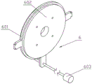
the present embodiment is described below with reference to fig. 1 to 14, and the sixth embodiment is further described in the present embodiment, the traverse mechanism 6 includes a cover-closing slip ring 601, a rotating plate 602, and a traverse motor 603, the cover-closing slip ring 601 is rotatably connected to the rotating plate 602, the cover-closing slip ring 601 is slidably connected between two slide rails 102, the cover-closing slip ring 601 can cover the dyeing cylinder 201, the traverse motor 603 is fixedly connected to the connecting plate 104, and the cover-closing slip ring 601 is connected to an output shaft of the cover-closing slip ring 601 through a thread.
The specific implementation mode is eight:
the following describes the present embodiment with reference to fig. 1 to 14, and the seventh embodiment is further described, where the stirring mechanism 7 includes a stirring cylinder 701, a placing plate 702, an inserting cylinder 703, a circular hole plate 704, a pushing column 705, a pulling circular plate 706 and rectangular insertion holes i 707, the placing plate 702 is fixedly connected to both sides of the stirring cylinder 701, the inserting cylinder 703 is fixedly connected to the front end of the stirring cylinder 701, the inserting cylinder 703 is insertable into the insertion slot 203, the circular hole plate 704 is fixedly connected to the front end of the stirring cylinder 701, a plurality of circular through holes ii are provided on the circular hole plate 704, the pushing column 705 is fixedly connected to the circular hole plate 704, the pushing column 705 can push the blocking column 207 to slide to the rear side, the pulling circular plate 706 is fixedly connected to the front end of the stirring cylinder 701, two rectangular insertion holes i 707 are provided on the pulling circular plate 706, and the two heating plates 502 can respectively pass through.
The specific implementation method nine:
the present embodiment is described below with reference to fig. 1 to 14, and the eighth embodiment is further described, where the pressing mechanism 8 includes a pressing circular plate 801, a sliding hole 802, two rectangular insertion holes ii 803, a sliding column 804, and a telescopic mechanism 805, the pressing circular plate 801 is provided with two sliding holes 802, the two placing plates 702 are respectively slidably connected in the two sliding holes 802, the pressing circular plate 801 is provided with two rectangular insertion holes ii 803, the two heating plates 502 can respectively pass through the two rectangular insertion holes ii 803, the pressing circular plate 801 is fixedly connected with the sliding column 804, the sliding column 804 is slidably connected to the rotating plate 602, the telescopic mechanism 805 is fixedly connected to the rotating plate 602, and the telescopic end of the telescopic mechanism 805 is fixedly connected to the sliding column 804.
The detailed implementation mode is ten:
the following describes the present embodiment with reference to fig. 1 to 14, and the present embodiment further describes an embodiment nine, where the power mechanism 9 includes a motor support 901, a power motor 902, a positioning turntable 903, positioning columns 904, and a positioning disk 905, the power motor 902 is fixedly connected to the motor support 901, the motor support 901 is fixedly connected to the covering slip ring 601, the rear end of an output shaft of the power motor 902 is fixedly connected to the positioning turntable 903, the positioning turntable 903 is slidably connected to the two positioning columns 904, the positioning disk 905 is fixedly connected to the covering slip ring 601, the positioning disk 905 is provided with two arc grooves, the two positioning columns 904 can be respectively inserted into the two arc grooves, a compression spring ii is fixedly connected between the positioning columns 904 and the positioning turntable 903, and the output shaft of the motor support 901 is fixedly connected to the stirring barrel 701.
The invention relates to silk stocking processing equipment, which has the working principle that:
as shown in fig. 1, the traversing mechanism 6 is not covered on the dyeing cylinder 2, the dye pipeline is connected in the feeding pipeline 202, the stirring mechanism 7 is not inserted into the dyeing cylinder 2, when in use, silk stockings to be dyed are placed on the two placing plates 702, the two positioning columns 904 are respectively inserted into the two arc grooves, so that the two placing plates 702 are both in a horizontal state, and the two heating plates 502 are both in a vertical state; starting a traverse motor 603, enabling an output shaft of the traverse motor 603 to rotate, enabling the output shaft of the traverse motor 603 to drive a covering slip ring 601 to slide between two slide rails 102 through threads, enabling the covering slip ring 601 to cover a dyeing cylinder body 201, enabling an agitating mechanism 7 to be inserted into the dyeing cylinder body 201, enabling two heating plates 502 to respectively penetrate through two rectangular jacks I707, enabling the two heating plates 502 to respectively penetrate through two rectangular jacks II 803, enabling an inserting cylinder 703 to be inserted into a slot 203, enabling a pushing column 705 to push a blocking column 207 to slide backwards, enabling a circular through hole I to be communicated with a circular through hole II, enabling dye to enter the agitating cylinder 701 through the circular through hole I and the circular through hole II, enabling the rear end of the agitating cylinder 701 to be sealed, and dyeing silk stockings through a plurality of holes formed in the agitating cylinder 701 as shown in FIG. 12; starting the water inlet pump 304, sucking water into the water inlet pipeline 303 by the water inlet pump 304, communicating the water inlet pipeline 303 with the water inlet cavity 301, enabling the water to enter the dyeing cylinder 201 through the arc-shaped pore plate I302, and dyeing silk stockings by mixing dye and water; the rotary baffle 501 is rotatably connected in the dyeing cylinder 201, the front side of the rotary baffle 501 and the water outlet cavity 401 are in contact with the water inlet cavity 301, the inner side of the rotary baffle 501 is rotatably connected to the front end of the feeding pipeline 202, and the rotary baffle 501 can block water mixed with dye to prevent the water from flowing out; the power motor 902 is started, the output shaft of the power motor 902 starts to rotate, the output shaft of the power motor 902 drives the stirring cylinder 701 to rotate, the stirring cylinder 701 drives the stirring mechanism 7 to rotate, the heating plate 502 can be driven to rotate when the circular plate 706 is pulled to rotate as the heating plate 502 penetrates through the rectangular insertion hole I707, the two heating plates 502 and the two placing plates 702 rotate to stir the water mixed with the dye, and the dyeing speed of silk stockings is increased; starting a telescopic mechanism 805, wherein the telescopic mechanism 805 can be a hydraulic cylinder or an electric push rod, or can be other mechanical structures capable of reciprocating, a telescopic end of the telescopic mechanism 805 drives a sliding column 804 to slide on a rotating plate 602 in a reciprocating manner, the sliding column 804 drives an extrusion circular plate 801 to slide on an agitating cylinder 701 in a reciprocating manner, the relative distance between the pulling circular plate 706 and the extrusion circular plate 801 is changed, the extrusion circular plate 801 extrudes silk stockings, and the silk stockings are in a state of being extruded with water and not being extruded with water, so that water absorption and extrusion circulation is formed, the silk stockings can be in faster contact with dye, and the silk stockings can be dyed more quickly; meanwhile, when the pressing round plate 801 moves closer to the pulling round plate 706, water between the pulling round plate 706 and the pressing round plate 801 is extruded out of the rectangular insertion hole I707 and the rectangular insertion hole II 803, and simultaneously the water is rapidly contacted with the heating plate 502, so that the heating plate 502 can control the water temperature more rapidly; when silk stocking dyeing is completed, the power motor 902 is closed, when attention is needed, the two positioning columns 904 are inserted into the two arc grooves, the power motor 902 is closed, the placing plate 702 is in a horizontal state when exiting from the dyeing cylinder 201, and the output shaft of the transverse moving motor 603 can rotate forward and backward.
It is to be understood that the above description is not intended to limit the present invention, and the present invention is not limited to the above examples, and that various changes, modifications, additions and substitutions which are within the spirit and scope of the present invention and which may be made by those skilled in the art are also within the scope of the present invention.
Claims (10)
1. The utility model provides a silk socks processing equipment, includes device support (1), dyeing section of thick bamboo (2), income water mechanism (3), goes out water mechanism (4), heating mechanism (5), sideslip mechanism (6), rabbling mechanism (7), extrusion mechanism (8) and power unit (9), its characterized in that: fixedly connected with dyeing section of thick bamboo (2) on device support (1), fixedly connected with goes into water mechanism (3) and goes out water mechanism (4) in dyeing section of thick bamboo (2), dyeing section of thick bamboo (2) internal rotation is connected with heating mechanism (5), sliding connection has sideslip mechanism (6) on device support (1), fixedly connected with rabbling mechanism (7) are gone up in sideslip mechanism (6), be connected with extruding means (8) on rabbling mechanism (7), fixedly connected with power unit (9) are gone up in sideslip mechanism (6), power unit (9) and rabbling mechanism (7) transmission are connected, rabbling mechanism (7) can insert in dyeing section of thick bamboo (2).
2. The silk stocking processing apparatus according to claim 1, wherein: the device support (1) comprises side supports (101), slide rails (102), connecting rings (103) and connecting plates (104), wherein the number of the side supports (101) is two, the slide rails (102) are fixedly connected to the inner sides of the two side supports (101), the connecting rings (103) are fixedly connected between the rear ends of the two side supports (101), and the connecting plates (104) are fixedly connected between the front ends of the two side supports (101).
3. The silk stocking processing apparatus according to claim 2, wherein: the dyeing cylinder (2) comprises a dyeing cylinder body (201), a feeding pipeline (202), an insertion groove (203) and a blocking mechanism (204), the dyeing cylinder body (201) is fixedly connected to a connecting ring (103), the rear end of the dyeing cylinder body (201) is fixedly connected with the feeding pipeline (202), the front end of the feeding pipeline (202) is provided with the insertion groove (203), the blocking mechanism (204) is fixedly connected into the feeding pipeline (202), the blocking mechanism (204) comprises a blocking bottom plate I (205), a blocking bottom plate II (206) and a blocking column (207), the blocking bottom plate I (205) and the blocking bottom plate II (206) are both fixedly connected into the feeding pipeline (202), the blocking bottom plate I (205) is provided with a plurality of circular through holes I, the blocking bottom plate II (206) is provided with tapered holes, the blocking column (207) is slidably connected onto the blocking bottom plate I (205), the front end of the blocking column (207) is propped in the tapered holes, a compression spring I is fixedly connected between the blocking column (207) and the blocking base plate I (205).
4. A hosiery processing machine according to claim 3, wherein: go into water mechanism (3) including income water cavity (301), circular arc orifice plate I (302), inlet pipe (303) and income water pump (304), the inboard fixedly connected with circular arc orifice plate I (302) of income water cavity (301), fixedly connected with inlet pipe (303) are gone up to income water cavity (301), inlet pipe (303) and inlet pipe cavity (301) intercommunication, are connected with into water pump (304) on inlet pipe (303), and inlet pipe cavity (301) fixed connection is in dyeing barrel (201).
5. The silk stocking processing apparatus according to claim 4, wherein: the water outlet mechanism (4) comprises a water outlet cavity (401), an arc hole plate II (402), a water outlet pipeline (403) and a water outlet pump (404), the arc hole plate II (402) is fixedly connected to the inner side of the water outlet cavity (401), the water outlet pipeline (403) is fixedly connected to the water outlet cavity (401), the water outlet pump (404) is connected to the water outlet pipeline (403), the water outlet pipeline (403) is communicated with the water outlet cavity (401), and the water outlet cavity (401) is fixedly connected to the dyeing cylinder body (201).
6. The silk stocking processing apparatus according to claim 5, wherein: heating mechanism (5) are including rotating baffle (501) and hot plate (502), rotate two hot plate (502) of fixedly connected with on baffle (501), rotate baffle (501) and rotate to be connected in dyeing barrel (201), rotate the front side of baffle (501) and go out water cavity (401) and go into water cavity (301) contact, rotate the inboard rotation of baffle (501) and connect the front end at income material pipeline (202).
7. The silk stocking processing apparatus according to claim 6, wherein: sideslip mechanism (6) close sliding ring (601), rotor plate (602) and sideslip motor (603) including the lid, the lid closes and rotates on sliding ring (601) and is connected with rotor plate (602), the lid closes sliding ring (601) sliding connection between two slide rails (102), the lid closes sliding ring (601) and can cover and close on dyeing barrel (201), sideslip motor (603) fixed connection is on connecting plate (104), the lid closes sliding ring (601) and closes on the output shaft that sliding ring (601) was closed to the lid through threaded connection.
8. The silk stocking processing apparatus according to claim 7, wherein: the stirring mechanism (7) comprises a stirring cylinder (701), a placing plate (702), an inserting cylinder (703), a round hole plate (704), a pushing column (705), a pulling round plate (706) and a rectangular insertion hole I (707), the equal fixedly connected with in both sides of stirring a section of thick bamboo (701) places board (702), the front end fixedly connected with of stirring a section of thick bamboo (701) inserts a section of thick bamboo (703), insert a section of thick bamboo (703) and can insert in slot (203), the front end fixedly connected with round hole board (704) of stirring a section of thick bamboo (701), be provided with a plurality of circular through-holes II on round hole board (704), fixedly connected with promotes post (705) on round hole board (704), it can promote to block post (207) and slide to the rear side to promote post (705), the front end fixedly connected with pulling plectane (706) of stirring a section of thick bamboo (701), be provided with two rectangle jacks I (707) on pulling plectane (706), two hot plates (502) can pass two rectangle jacks I (707.
9. The hosiery processing apparatus of claim 8, wherein: extrusion mechanism (8) are including extruding plectane (801), sliding hole (802), rectangle jack II (803), slip post (804) and telescopic machanism (805), be provided with two sliding hole (802) on extruding plectane (801), two place board (702) sliding connection respectively in two sliding hole (802), be provided with two rectangle jack II (803) on extruding plectane (801), two hot plate (502) can pass two rectangle jack II (803) respectively, fixedly connected with slip post (804) on extruding plectane (801), slip post (804) sliding connection is on rotor plate (602), telescopic machanism (805) fixed connection is on rotor plate (602), telescopic machanism's (805) telescopic end fixed connection is on slip post (804).
10. The hosiery processing apparatus of claim 9, wherein: power unit (9) are including motor support (901), motor power (902), location carousel (903), reference column (904) and positioning disk (905), fixedly connected with motor power (902) on motor support (901), motor support (901) fixed connection is on covering sliding ring (601), the rear end fixedly connected with location carousel (903) of motor power (902) output shaft, sliding connection has two reference columns (904) on location carousel (903), positioning disk (905) fixed connection is on covering sliding ring (601), be provided with two circular arc grooves on positioning disk (905), two circular arc inslots can be inserted respectively in two reference columns (904), fixedly connected with compression spring II between reference column (904) and the location carousel (903), the output shaft fixed connection of motor support (901) is on stirring section of thick bamboo (701).
Priority Applications (1)
| Application Number | Priority Date | Filing Date | Title |
|---|---|---|---|
| CN202010550844.9A CN111663274B (en) | 2020-06-16 | 2020-06-16 | Silk stocking processing equipment |
Applications Claiming Priority (1)
| Application Number | Priority Date | Filing Date | Title |
|---|---|---|---|
| CN202010550844.9A CN111663274B (en) | 2020-06-16 | 2020-06-16 | Silk stocking processing equipment |
Publications (2)
| Publication Number | Publication Date |
|---|---|
| CN111663274A true CN111663274A (en) | 2020-09-15 |
| CN111663274B CN111663274B (en) | 2022-09-06 |
Family
ID=72388056
Family Applications (1)
| Application Number | Title | Priority Date | Filing Date |
|---|---|---|---|
| CN202010550844.9A Active CN111663274B (en) | 2020-06-16 | 2020-06-16 | Silk stocking processing equipment |
Country Status (1)
| Country | Link |
|---|---|
| CN (1) | CN111663274B (en) |
Cited By (1)
| Publication number | Priority date | Publication date | Assignee | Title |
|---|---|---|---|---|
| CN119640525A (en) * | 2025-02-17 | 2025-03-18 | 上海华翔羊毛衫有限公司 | A wool sweater dyeing machine |
Citations (13)
| Publication number | Priority date | Publication date | Assignee | Title |
|---|---|---|---|---|
| WO1996017990A1 (en) * | 1994-12-07 | 1996-06-13 | Leonard System | Method for short bath dyeing, and machines implementing such method |
| CN2255441Y (en) * | 1996-01-12 | 1997-06-04 | 曾绍录 | Reciprocating-squeezing type washing machine |
| WO2011004824A1 (en) * | 2009-07-09 | 2011-01-13 | グンゼ株式会社 | Rotary dyeing device and automatic dyeing device |
| CN203144716U (en) * | 2012-02-28 | 2013-08-21 | 高华奥秘有限公司 | Garment Dyeing Machine |
| CN105088605A (en) * | 2014-05-23 | 2015-11-25 | 青岛海尔洗衣机有限公司 | A reciprocating squeezing type and rotation type washing machine |
| CN204845308U (en) * | 2015-06-01 | 2015-12-09 | 郭嘉川 | Column work piece engraver |
| CN108660660A (en) * | 2018-08-31 | 2018-10-16 | 湖北福兴织业有限公司 | One kind being used for hosiery dyeing processing unit (plant) |
| CN207987506U (en) * | 2018-03-16 | 2018-10-19 | 曹云生 | A kind of automatic garment dyeing machine |
| CN109497632A (en) * | 2018-12-26 | 2019-03-22 | 海宁亚润袜业有限公司 | A kind of production method and its equipment of panty hose |
| CN109736033A (en) * | 2019-01-24 | 2019-05-10 | 嘉兴市鸿峰漂染有限公司 | Garment dyeing machine |
| CN209098968U (en) * | 2018-09-28 | 2019-07-12 | 苏州希望纺织印染有限公司 | Overflow dyeing machine |
| CN209428762U (en) * | 2019-01-03 | 2019-09-24 | 海宁亚润袜业有限公司 | A kind of energy saving type dyeing machine for socks |
| CN209584584U (en) * | 2019-01-15 | 2019-11-05 | 嘉兴市腾旺染整有限公司 | A kind of efficient garment dyeing machine |
-
2020
- 2020-06-16 CN CN202010550844.9A patent/CN111663274B/en active Active
Patent Citations (13)
| Publication number | Priority date | Publication date | Assignee | Title |
|---|---|---|---|---|
| WO1996017990A1 (en) * | 1994-12-07 | 1996-06-13 | Leonard System | Method for short bath dyeing, and machines implementing such method |
| CN2255441Y (en) * | 1996-01-12 | 1997-06-04 | 曾绍录 | Reciprocating-squeezing type washing machine |
| WO2011004824A1 (en) * | 2009-07-09 | 2011-01-13 | グンゼ株式会社 | Rotary dyeing device and automatic dyeing device |
| CN203144716U (en) * | 2012-02-28 | 2013-08-21 | 高华奥秘有限公司 | Garment Dyeing Machine |
| CN105088605A (en) * | 2014-05-23 | 2015-11-25 | 青岛海尔洗衣机有限公司 | A reciprocating squeezing type and rotation type washing machine |
| CN204845308U (en) * | 2015-06-01 | 2015-12-09 | 郭嘉川 | Column work piece engraver |
| CN207987506U (en) * | 2018-03-16 | 2018-10-19 | 曹云生 | A kind of automatic garment dyeing machine |
| CN108660660A (en) * | 2018-08-31 | 2018-10-16 | 湖北福兴织业有限公司 | One kind being used for hosiery dyeing processing unit (plant) |
| CN209098968U (en) * | 2018-09-28 | 2019-07-12 | 苏州希望纺织印染有限公司 | Overflow dyeing machine |
| CN109497632A (en) * | 2018-12-26 | 2019-03-22 | 海宁亚润袜业有限公司 | A kind of production method and its equipment of panty hose |
| CN209428762U (en) * | 2019-01-03 | 2019-09-24 | 海宁亚润袜业有限公司 | A kind of energy saving type dyeing machine for socks |
| CN209584584U (en) * | 2019-01-15 | 2019-11-05 | 嘉兴市腾旺染整有限公司 | A kind of efficient garment dyeing machine |
| CN109736033A (en) * | 2019-01-24 | 2019-05-10 | 嘉兴市鸿峰漂染有限公司 | Garment dyeing machine |
Cited By (1)
| Publication number | Priority date | Publication date | Assignee | Title |
|---|---|---|---|---|
| CN119640525A (en) * | 2025-02-17 | 2025-03-18 | 上海华翔羊毛衫有限公司 | A wool sweater dyeing machine |
Also Published As
| Publication number | Publication date |
|---|---|
| CN111663274B (en) | 2022-09-06 |
Similar Documents
| Publication | Publication Date | Title |
|---|---|---|
| CN111663274B (en) | Silk stocking processing equipment | |
| CN116254613B (en) | Extrusion device for extinction nylon production | |
| CN111495224A (en) | Cosmetic cream frost production cooling integral type equipment | |
| CN213919096U (en) | Rubber mixing machine roller heat-conducting oil heating structure for plastic processing | |
| CN111011564A (en) | Chocolate 3D printer extrusion device | |
| CN214159481U (en) | High-efficiency speed-multiplying stirring device | |
| CN221812596U (en) | Seed dressing machine capable of atomizing and spraying liquid microbial agent | |
| CN112090324A (en) | Mechanical seal stirring device | |
| CN111974268A (en) | Printing ink heat preservation stirred tank | |
| CN213077689U (en) | Plant extract filter equipment | |
| CN213556569U (en) | Stirring device for efficient environment-friendly magnesium silicate lithium paint mist coagulant | |
| CN221062473U (en) | Mixing equipment for special silica gel production | |
| CN222034519U (en) | Liquid medicine mixing device for sewage treatment | |
| CN214765009U (en) | Constant-temperature blending device for refining ethoxymethylene malononitrile | |
| CN221093803U (en) | Sewage treatment dosing equipment | |
| CN112176603B (en) | Tie-dyeing equipment for environment-friendly silk fabrics | |
| CN217962108U (en) | Environmental protection emulsion paint blending device of convenient control | |
| CN111020932A (en) | Dyeing apparatus is used in non-woven fabrics production | |
| CN113789630A (en) | Low bath ratio level dyeing automatic dosing dyeing device | |
| CN220026698U (en) | Textile size blending device | |
| CN119281272B (en) | High-efficiency mixing device for synthesizing high-temperature-resistant block polysulfate sulfonate | |
| CN221523039U (en) | Cloth dyeing tank for textile processing | |
| CN220469884U (en) | Injection structure of oilfield water injection profile control agent | |
| CN223920461U (en) | Automatic waste medicine bag clamping device of medicine decocting room | |
| CN221207579U (en) | A mixer for uniform mixing |
Legal Events
| Date | Code | Title | Description |
|---|---|---|---|
| PB01 | Publication | ||
| PB01 | Publication | ||
| SE01 | Entry into force of request for substantive examination | ||
| SE01 | Entry into force of request for substantive examination | ||
| GR01 | Patent grant | ||
| GR01 | Patent grant |