CN111663261A - Textile dyeing device - Google Patents
Textile dyeing device Download PDFInfo
- Publication number
- CN111663261A CN111663261A CN202010536318.7A CN202010536318A CN111663261A CN 111663261 A CN111663261 A CN 111663261A CN 202010536318 A CN202010536318 A CN 202010536318A CN 111663261 A CN111663261 A CN 111663261A
- Authority
- CN
- China
- Prior art keywords
- frame
- fixed
- coating
- rod
- textile dyeing
- Prior art date
- Legal status (The legal status is an assumption and is not a legal conclusion. Google has not performed a legal analysis and makes no representation as to the accuracy of the status listed.)
- Pending
Links
- 238000004043 dyeing Methods 0.000 title claims abstract description 37
- 239000004753 textile Substances 0.000 title claims abstract description 19
- 239000011248 coating agent Substances 0.000 claims abstract description 40
- 238000000576 coating method Methods 0.000 claims abstract description 40
- 238000003892 spreading Methods 0.000 claims abstract description 20
- 230000007480 spreading Effects 0.000 claims abstract description 19
- 230000005540 biological transmission Effects 0.000 claims abstract description 11
- 238000001125 extrusion Methods 0.000 claims description 9
- 230000007306 turnover Effects 0.000 claims description 5
- 239000000758 substrate Substances 0.000 claims description 4
- 239000007921 spray Substances 0.000 claims description 3
- 230000000694 effects Effects 0.000 abstract description 6
- 239000004744 fabric Substances 0.000 description 18
- 239000000975 dye Substances 0.000 description 17
- 239000000463 material Substances 0.000 description 5
- 239000000835 fiber Substances 0.000 description 3
- 238000009434 installation Methods 0.000 description 3
- 230000007246 mechanism Effects 0.000 description 3
- 238000000034 method Methods 0.000 description 3
- 230000008569 process Effects 0.000 description 3
- 230000001680 brushing effect Effects 0.000 description 2
- 238000001035 drying Methods 0.000 description 2
- 239000000049 pigment Substances 0.000 description 2
- 238000002791 soaking Methods 0.000 description 2
- 238000009987 spinning Methods 0.000 description 2
- 239000012752 auxiliary agent Substances 0.000 description 1
- 230000009286 beneficial effect Effects 0.000 description 1
- 238000010014 continuous dyeing Methods 0.000 description 1
- 230000008878 coupling Effects 0.000 description 1
- 238000010168 coupling process Methods 0.000 description 1
- 238000005859 coupling reaction Methods 0.000 description 1
- 230000007547 defect Effects 0.000 description 1
- 238000010586 diagram Methods 0.000 description 1
- 238000004519 manufacturing process Methods 0.000 description 1
- 239000000126 substance Substances 0.000 description 1
- XLYOFNOQVPJJNP-UHFFFAOYSA-N water Substances O XLYOFNOQVPJJNP-UHFFFAOYSA-N 0.000 description 1
- 238000004804 winding Methods 0.000 description 1
Images


Classifications
-
- D—TEXTILES; PAPER
- D06—TREATMENT OF TEXTILES OR THE LIKE; LAUNDERING; FLEXIBLE MATERIALS NOT OTHERWISE PROVIDED FOR
- D06B—TREATING TEXTILE MATERIALS USING LIQUIDS, GASES OR VAPOURS
- D06B1/00—Applying liquids, gases or vapours onto textile materials to effect treatment, e.g. washing, dyeing, bleaching, sizing or impregnating
- D06B1/04—Applying liquids, gases or vapours onto textile materials to effect treatment, e.g. washing, dyeing, bleaching, sizing or impregnating by pouring or allowing to flow on to the surface of the textile material
- D06B1/06—Applying liquids, gases or vapours onto textile materials to effect treatment, e.g. washing, dyeing, bleaching, sizing or impregnating by pouring or allowing to flow on to the surface of the textile material flowing along an inclined surface
-
- D—TEXTILES; PAPER
- D06—TREATMENT OF TEXTILES OR THE LIKE; LAUNDERING; FLEXIBLE MATERIALS NOT OTHERWISE PROVIDED FOR
- D06B—TREATING TEXTILE MATERIALS USING LIQUIDS, GASES OR VAPOURS
- D06B1/00—Applying liquids, gases or vapours onto textile materials to effect treatment, e.g. washing, dyeing, bleaching, sizing or impregnating
- D06B1/10—Applying liquids, gases or vapours onto textile materials to effect treatment, e.g. washing, dyeing, bleaching, sizing or impregnating by contact with a member carrying the treating material
- D06B1/12—Applying liquids, gases or vapours onto textile materials to effect treatment, e.g. washing, dyeing, bleaching, sizing or impregnating by contact with a member carrying the treating material by rubbing contact, e.g. with brushes or pads
-
- D—TEXTILES; PAPER
- D06—TREATMENT OF TEXTILES OR THE LIKE; LAUNDERING; FLEXIBLE MATERIALS NOT OTHERWISE PROVIDED FOR
- D06B—TREATING TEXTILE MATERIALS USING LIQUIDS, GASES OR VAPOURS
- D06B23/00—Component parts, details, or accessories of apparatus or machines, specially adapted for the treating of textile materials, not restricted to a particular kind of apparatus, provided for in groups D06B1/00 - D06B21/00
- D06B23/04—Carriers or supports for textile materials to be treated
Landscapes
- Engineering & Computer Science (AREA)
- Textile Engineering (AREA)
- Treatment Of Fiber Materials (AREA)
Abstract
The invention relates to the technical field of textiles, in particular to a textile dyeing device which comprises an operation machine table, wherein a spreading platform table is arranged on the operation machine table, the spreading platform table is obliquely arranged on the operation machine table, an operation frame is arranged on the operation machine table, a fixed frame is arranged on the operation frame, a telescopic rod is arranged on the fixed frame through a movable shaft, a coating frame is arranged at the movable end of the bottom of the telescopic rod, a fixed frame is arranged at the rear side of the operation frame, a transmission motor is arranged on the fixed frame, a transmission disc is arranged at the driving end of the transmission motor, a first connecting bolt is arranged at the disc surface edge of the transmission disc, a second connecting bolt is arranged at the fixed end of the telescopic rod, and a transmission rod is arranged between the first connecting bolt and the second connecting. The invention can improve the dyeing effect, ensure the coating uniformity and avoid the problem of incomplete dyeing.
Description
Technical Field
The invention relates to the technical field of spinning, in particular to a spinning dyeing device.
Background
Dyeing is a process of dyeing a textile with a color having a certain fastness, and is a process of giving a certain color to the textile by means of physicochemical or chemical combination of a dye and a fiber, or by chemically generating a pigment on the fiber, so that, in general, a dyeing system for visible textiles is composed of a dye (or a pigment), a fiber and water (or an auxiliary agent). The dyeing machine is an open-width continuous dyeing combination machine, has higher production efficiency, is suitable for dyeing equipment of large-batch varieties, but the dye is easy to have uneven dyeing in the dyeing process, the drying efficiency of the dye is lower, the dye can not be dried before being collected, the dye is sticky, and the dyeing effect of the dye is easy to be influenced, so that the textile dyeing device is provided to solve the problem.
Chinese patent (No. CN 209636487U) discloses a textile dyeing device, which dyes cloth through a multi-stage roll shaft mechanism, but has certain defects that the uniformity of the dye liquor coated on the cloth can not be ensured, and particularly for the single coating of the cloth through a round roll surface, the round roll surface and the cloth are only in a linear contact surface, and the phenomenon of coating in place often exists.
Disclosure of Invention
The present invention is directed to a textile dyeing apparatus to solve the above problems of the prior art.
In order to achieve the purpose, the invention provides the following technical scheme:
a textile dyeing device comprises an operation machine platform, wherein a spreading platform is arranged on the operation machine platform, the spreading carrying platform is obliquely arranged on the operation machine platform, auxiliary rollers are arranged at two ends of the spreading carrying platform, a supporting frame is arranged on the side surface of the operating machine table, a turnover roller is arranged on the supporting frame, an operating frame is arranged on the operating machine table, a fixed frame is arranged on the operation frame, a telescopic rod is arranged on the fixed frame through a movable shaft, the movable end at the bottom of the telescopic rod is provided with a coating frame, the rear side of the operation frame is provided with a fixed frame, the fixed frame is provided with a transmission motor, the driving end of the transmission motor is provided with a transmission disc, first connecting bolt is installed at the quotation border of driving plate, the second connecting bolt is installed to the stiff end of telescopic link, install the transfer line between first connecting bolt and the second connecting bolt.
As a further scheme of the invention: the inclination angle of the spreading stage is 10-15 deg.
As a further scheme of the invention: the spreading carrying platform is provided with a mounting rack, and the mounting rack is provided with a solution spray head.
As a further scheme of the invention: the coating device is characterized in that sliding blocks are installed at two ends of the coating frame, side plates are arranged on two side edges of the mounting frame, limiting grooves are formed in the side plates, and the sliding blocks are installed in the limiting grooves in a limiting mode.
As a still further scheme of the invention: the main part of coating frame is fixed baseplate and coating brush, be provided with the elastic connection pole between fixed baseplate and the coating brush, the elastic connection pole is interior hollow structure, the dead lever is installed to the elastic connection pole capital expenditure, the bottom rod end cover of dead lever is equipped with movable sleeve, movable sleeve's bottom again with coating brush fixed mounting, the winding has the extrusion spring on the dead lever, extrusion spring coupling is between fixed baseplate and coating brush.
Compared with the prior art, the invention has the beneficial effects that:
the application will spread the microscope carrier design and be the tilting structure, when the operation, will spread the cloth on the microscope carrier of spreading, carry out the defeated material from bottom to top, during the dyeing, the dye liquor flows from top to bottom to make the transmission direction of cloth and the direction of flow of dye liquor relative, the dye liquor of being convenient for is to soaking of cloth, from improving dyeing effect.
During dyeing operation, this application sets up the operation frame as the drive mechanism of this application, and drive motor drives the drive plate motion, and then drives the telescopic link through the transfer line and use the loose axle to swing as the axis, can reciprocate to brush the operation to the cloth, improves the coating effect of dyestuff through the mode of brushing. The coating frame moves along the direction of the limiting groove during operation, and then is consistent with the conveying angle of the cloth, so that the coating uniformity is ensured.
In order to improve the coating quality, the coating brush is installed on the fixed baseplate through the elastic connecting rod, and downward supporting thrust is given through the extrusion spring, so that the brush surface of the coating brush is tightly attached to the material surface of the cloth, the dyeing contact degree is increased, and the problem of incomplete dyeing is avoided.
It is to be understood that both the foregoing general description and the following detailed description are exemplary and explanatory only and are not restrictive of the application.
Drawings
The accompanying drawings, which are incorporated in and constitute a part of this specification, illustrate embodiments consistent with the present application and together with the description, serve to explain the principles of the application. Also, the drawings and the description are not intended to limit the scope of the present concepts in any way, but rather to illustrate the concepts of the present disclosure to those skilled in the art by reference to specific embodiments.
FIG. 1 is a schematic structural diagram of the present invention.
Fig. 2 is a schematic structural view of the mounting frame of the present invention.
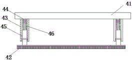
FIG. 3 is a schematic view of the structure of the coating frame of the present invention.
In the figure: 1-operation machine table, 11-spreading carrying table, 12-auxiliary roller, 13-supporting frame, 14-turnover roller, 2-operation frame, 21-fixed frame, 22-movable shaft, 23-telescopic rod, 24-fixed frame, 25-transmission motor, 26-transmission disc, 27-first connection bolt, 28-transmission rod, 29-second connection bolt, 3-mounting frame, 31-solution sprayer, 32-side plate, 33-limiting groove, 4-coating frame, 41-fixed base plate, 42-coating brush, 43-elastic connecting rod, 44-fixed rod, 45-movable sleeve and 46-extrusion spring.
Detailed Description
The technical solutions in the embodiments of the present invention will be clearly and completely described below with reference to the drawings in the embodiments of the present invention, examples of which are shown in the drawings. When the following description refers to the accompanying drawings, like numbers in different drawings represent the same or similar elements, unless otherwise indicated.
It is to be understood that the described embodiments are merely exemplary of the invention, and not restrictive of the full scope of the invention. All other embodiments, which can be derived by a person skilled in the art from the embodiments given herein without making any creative effort, shall fall within the protection scope of the present invention.
The first embodiment is as follows:
referring to fig. 1 and 2, a textile dyeing apparatus includes an operation machine 1, a spreading platform 11 is disposed on the operation machine 1, the spreading platform 11 is disposed on the operation machine 1 in an inclined direction, and an inclination angle of the spreading platform 11 is 10 ° to 15 °. The two ends of the spreading carrying platform 11 are respectively provided with an auxiliary roller 12, the auxiliary rollers 12 improve the smoothness of cloth conveying, so that the problem of cloth wrinkling is solved, the side surface of the operation machine platform 1 is provided with a support frame 13, the support frame 13 is provided with a turnover roller 14, and the turnover roller 14 assists the turnover of materials to a drying process after dyeing.
This application will spread microscope carrier 11 design for the tilting structure, when the operation, spreads the cloth on microscope carrier 11, from bottom to top carries out the defeated material, and during the dyeing, the dye liquor flows from top to bottom to make the transmission direction of cloth and the direction of flow of dye liquor relative, the dye liquor of being convenient for is to soaking of cloth, from improving dyeing effect.
Install operation frame 2 on the operation board 1, install mount 21 on the operation frame 2, install telescopic link 23 through loose axle 22 on the mount 21, coating frame 4 is installed to the bottom expansion end of telescopic link 23, mount 24 is installed to the rear side of operation frame 2, install drive motor 25 on the mount 24, drive plate 26 is installed to drive motor 25's drive end, first connecting bolt 27 is installed at drive plate 26's quotation border, second connecting bolt 29 is installed to the stiff end of telescopic link 23, install transfer line 28 between first connecting bolt 27 and the second connecting bolt 29. The spreading table 11 is provided with an installation frame 3, the installation frame 3 is provided with a solution spray head 31, sliding blocks 41 are installed at two ends of the spreading frame 4, side plates 32 are arranged on two side edges of the installation frame 3, a limiting groove 33 is formed in each side plate 32, and the sliding blocks 41 are installed in the limiting grooves 33 in a limiting mode.
During dyeing operation, this application sets up operation frame 2 and regards as the drive mechanism of this application, and drive motor 25 drives the motion of driving disc 26, and then drives telescopic link 23 through transfer line 28 and uses loose axle 22 to swing as the axis, can reciprocate to brush the operation to the cloth, improves the coating effect of dyestuff through the mode of brushing. The coating frame 4 moves along the direction of the limiting groove 33 during operation, and then is consistent with the conveying angle of the cloth, so that the coating uniformity is ensured.
Example two:
referring to fig. 1 and fig. 3, the embodiment is further optimized as an embodiment, on the basis of which the main body of the coating frame 4 is a fixed substrate 41 and a coating brush 42, an elastic connecting rod 43 is arranged between the fixed substrate 41 and the coating brush 42, the elastic connecting rod 43 is of an inner hollow structure, a fixed rod 44 is installed in the elastic connecting rod 43, a movable sleeve 45 is sleeved at a rod end at the bottom of the fixed rod 44, the bottom end of the movable sleeve 45 is fixedly installed with the coating brush 42, an extrusion spring 46 is wound on the fixed rod 44, and the extrusion spring 46 is connected between the fixed substrate 41 and the coating brush 42.
In order to improve the coating quality, the coating brush 42 is arranged on the fixed base plate 41 through the elastic connecting rod 43, and downward supporting thrust is given through the extrusion spring 46, so that the brush surface of the coating brush 42 is tightly attached to the material surface of the cloth, the dyeing contact degree is increased, and the problem of incomplete dyeing is avoided.
It will be evident to those skilled in the art that the invention is not limited to the details of the foregoing illustrative embodiments, and that the present invention may be embodied in other specific forms without departing from the spirit or essential attributes thereof. The present embodiments are therefore to be considered in all respects as illustrative and not restrictive, the scope of the invention being indicated by the appended claims rather than by the foregoing description, and all changes which come within the meaning and range of equivalency of the claims are therefore intended to be embraced therein. Any reference sign in a claim should not be construed as limiting the claim concerned.
Furthermore, it should be understood that although the present description refers to embodiments, not every embodiment may contain only a single embodiment, and such description is for clarity only, and those skilled in the art should integrate the description, and the embodiments may be combined as appropriate to form other embodiments understood by those skilled in the art.
Claims (6)
1. A textile dyeing device comprises an operation machine table (1), wherein a spreading platform table (11) is arranged on the operation machine table (1), the spreading platform table (11) is arranged on the operation machine table (1) in an inclined manner, and the textile dyeing device is characterized in that auxiliary rollers (12) are arranged at two ends of the spreading platform table (11), a support frame (13) is arranged on the side surface of the operation machine table (1), a turnover roller (14) is arranged on the support frame (13), an operation frame (2) is arranged on the operation machine table (1), a fixed frame (21) is arranged on the operation frame (2), a telescopic rod (23) is arranged on the fixed frame (21) through a movable shaft (22), a coating frame (4) is arranged at the movable end of the bottom of the telescopic rod (23), a fixed frame (24) is arranged at the rear side of the operation frame (2), and a transmission motor (25) is arranged on the fixed frame (24, drive plate (26) are installed to the drive end of drive motor (25), first connecting bolt (27) are installed to the quotation border of drive plate (26), second connecting bolt (29) are installed to the stiff end of telescopic link (23), install transfer line (28) between first connecting bolt (27) and second connecting bolt (29).
2. Textile dyeing unit according to claim 1, characterized in that the inclination of the spreading stage (11) is 10 ° to 15 °.
3. Textile dyeing unit according to claim 2, characterized in that a mounting frame (3) is provided on the spreading stage (11), a solution spray head (31) being provided on the mounting frame (3).
4. The textile dyeing device according to claim 1, characterized in that two ends of the coating frame (4) are provided with sliding blocks (41), two side edges of the mounting frame (3) are provided with side plates (32), the side plates (32) are provided with limiting grooves (33), and the sliding blocks (41) are installed in the limiting grooves (33) in a limiting manner.
5. Textile dyeing unit according to any one of claims 1 to 4, characterized in that the body of the coating holder (4) is a fixed base plate (41) and a coating brush (42), between which fixed base plate (41) and coating brush (42) there is arranged an elastic connecting rod (43).
6. The textile dyeing apparatus according to claim 5, characterized in that the elastic connecting rod (43) is of an inner hollow structure, a fixed rod (44) is installed in the elastic connecting rod (43), a movable sleeve (45) is sleeved on the bottom rod end of the fixed rod (44), the bottom end of the movable sleeve (45) is fixedly installed with the coating brush (42), an extrusion spring (46) is wound on the fixed rod (44), and the extrusion spring (46) is connected between the fixed substrate (41) and the coating brush (42).
Priority Applications (1)
| Application Number | Priority Date | Filing Date | Title |
|---|---|---|---|
| CN202010536318.7A CN111663261A (en) | 2020-06-12 | 2020-06-12 | Textile dyeing device |
Applications Claiming Priority (1)
| Application Number | Priority Date | Filing Date | Title |
|---|---|---|---|
| CN202010536318.7A CN111663261A (en) | 2020-06-12 | 2020-06-12 | Textile dyeing device |
Publications (1)
| Publication Number | Publication Date |
|---|---|
| CN111663261A true CN111663261A (en) | 2020-09-15 |
Family
ID=72387354
Family Applications (1)
| Application Number | Title | Priority Date | Filing Date |
|---|---|---|---|
| CN202010536318.7A Pending CN111663261A (en) | 2020-06-12 | 2020-06-12 | Textile dyeing device |
Country Status (1)
| Country | Link |
|---|---|
| CN (1) | CN111663261A (en) |
Cited By (1)
| Publication number | Priority date | Publication date | Assignee | Title |
|---|---|---|---|---|
| CN113560127A (en) * | 2021-07-14 | 2021-10-29 | 中天(中国)工业有限公司 | An essential oil coating device |
Citations (10)
| Publication number | Priority date | Publication date | Assignee | Title |
|---|---|---|---|---|
| CN205821697U (en) * | 2016-06-24 | 2016-12-21 | 江苏新宏基纺织科技有限公司 | A kind of dyeing apparatus of pair of material cylinder |
| CN107326569A (en) * | 2017-08-26 | 2017-11-07 | 梅明会 | A kind of good textile dyeing device of Color |
| CN107620180A (en) * | 2017-11-02 | 2018-01-23 | 界首市永顺服饰有限公司 | A kind of cloth dyeing and printing device for garment production |
| CN107956066A (en) * | 2018-01-20 | 2018-04-24 | 海宁天荣纺织有限公司 | A kind of cloth dyeing apparatus |
| CN108396478A (en) * | 2018-05-13 | 2018-08-14 | 徐美琴 | A kind of dyeing machine reducing rework rate |
| CN109518376A (en) * | 2017-09-18 | 2019-03-26 | 湖北智权专利技术应用开发有限公司 | A kind of liquid-jet device with uniform coloring |
| CN110205762A (en) * | 2019-02-14 | 2019-09-06 | 浙江创宇印染有限公司 | A kind of dyeing of terylene cloth |
| CN110424112A (en) * | 2019-07-17 | 2019-11-08 | 安徽宜民新材料科技有限公司 | A kind of cloth sprays uniform spray-dyeing device and its application method |
| CN210481726U (en) * | 2019-07-03 | 2020-05-08 | 桐乡市荣翔染整有限公司 | Dyeing device with automatic tiling function |
| CN211689502U (en) * | 2019-12-12 | 2020-10-16 | 太仓市良艳印染有限公司 | Energy-saving dyeing machine |
-
2020
- 2020-06-12 CN CN202010536318.7A patent/CN111663261A/en active Pending
Patent Citations (10)
| Publication number | Priority date | Publication date | Assignee | Title |
|---|---|---|---|---|
| CN205821697U (en) * | 2016-06-24 | 2016-12-21 | 江苏新宏基纺织科技有限公司 | A kind of dyeing apparatus of pair of material cylinder |
| CN107326569A (en) * | 2017-08-26 | 2017-11-07 | 梅明会 | A kind of good textile dyeing device of Color |
| CN109518376A (en) * | 2017-09-18 | 2019-03-26 | 湖北智权专利技术应用开发有限公司 | A kind of liquid-jet device with uniform coloring |
| CN107620180A (en) * | 2017-11-02 | 2018-01-23 | 界首市永顺服饰有限公司 | A kind of cloth dyeing and printing device for garment production |
| CN107956066A (en) * | 2018-01-20 | 2018-04-24 | 海宁天荣纺织有限公司 | A kind of cloth dyeing apparatus |
| CN108396478A (en) * | 2018-05-13 | 2018-08-14 | 徐美琴 | A kind of dyeing machine reducing rework rate |
| CN110205762A (en) * | 2019-02-14 | 2019-09-06 | 浙江创宇印染有限公司 | A kind of dyeing of terylene cloth |
| CN210481726U (en) * | 2019-07-03 | 2020-05-08 | 桐乡市荣翔染整有限公司 | Dyeing device with automatic tiling function |
| CN110424112A (en) * | 2019-07-17 | 2019-11-08 | 安徽宜民新材料科技有限公司 | A kind of cloth sprays uniform spray-dyeing device and its application method |
| CN211689502U (en) * | 2019-12-12 | 2020-10-16 | 太仓市良艳印染有限公司 | Energy-saving dyeing machine |
Cited By (1)
| Publication number | Priority date | Publication date | Assignee | Title |
|---|---|---|---|---|
| CN113560127A (en) * | 2021-07-14 | 2021-10-29 | 中天(中国)工业有限公司 | An essential oil coating device |
Similar Documents
| Publication | Publication Date | Title |
|---|---|---|
| CN109334254B (en) | Double-sided printing method and double-sided printing machine | |
| CN215713914U (en) | Clean printing and dyeing device of little water of dacron knitted fabric high colour fastness | |
| JPH09119075A (en) | Continuous dyeing method of spun yarn with reactive dye and apparatus for carrying out this method | |
| CN111942002A (en) | Cloth printing production line and process flow thereof | |
| CN118639410B (en) | Environmentally friendly printing and dyeing equipment for polyester fabrics | |
| CN112226938A (en) | Textile thread dyeing device for spinning | |
| CN110699891A (en) | Dyeing process for polyester fiber braided fabric | |
| CN111962308A (en) | Chemical fiber cloth flame-retardant adhesive coating process | |
| CN220927193U (en) | Textile dyeing device with good dyeing effect | |
| CN111411465B (en) | A kind of waterproof cloth production equipment | |
| CN216712459U (en) | Alternate finishing device for blended fabric | |
| CN108708109B (en) | Device for salt-free dyeing of uncooked and bleached cotton textile by using reactive dye | |
| CN109736101A (en) | The production technology of waterproof and grease proofing easy decontamination environment-friendly polyester fabric | |
| CN213295775U (en) | Polyester fiber textile dyeing device | |
| CN212834484U (en) | A reactive dye salt-free dyeing device | |
| CN217399165U (en) | Waterproof tectorial membrane is along with hair surface fabric mixed flow dyeing and finishing device | |
| CN118065067A (en) | A low-temperature dyeing device for textile fibers | |
| CN216635871U (en) | Non-woven fabric pattern printing equipment | |
| CN220503450U (en) | Device for dyeing cloth at low temperature | |
| CN222160635U (en) | A high-temperature steaming, color-fixing, dyeing and finishing device for polyester-cotton knitted fabric | |
| CN112609352A (en) | Dyeing apparatus is used in processing of knitting fabrics | |
| CN217973693U (en) | Clean printing and dyeing device of dacron knitted fabric's few water | |
| CN220728813U (en) | Drying device for printing and dyeing of outdoor products | |
| CN223823016U (en) | A wrinkle-resistant fabric processing guide mechanism | |
| CN221678262U (en) | Water-based paint rotary screen printing equipment |
Legal Events
| Date | Code | Title | Description |
|---|---|---|---|
| PB01 | Publication | ||
| PB01 | Publication | ||
| SE01 | Entry into force of request for substantive examination | ||
| SE01 | Entry into force of request for substantive examination | ||
| WD01 | Invention patent application deemed withdrawn after publication |
Application publication date: 20200915 |
|
| WD01 | Invention patent application deemed withdrawn after publication |