CN111663253B - Hemming sewing machine for round fabric - Google Patents
Hemming sewing machine for round fabric Download PDFInfo
- Publication number
- CN111663253B CN111663253B CN202010134787.6A CN202010134787A CN111663253B CN 111663253 B CN111663253 B CN 111663253B CN 202010134787 A CN202010134787 A CN 202010134787A CN 111663253 B CN111663253 B CN 111663253B
- Authority
- CN
- China
- Prior art keywords
- fabric
- round
- edge
- sewing
- hemming
- Prior art date
- Legal status (The legal status is an assumption and is not a legal conclusion. Google has not performed a legal analysis and makes no representation as to the accuracy of the status listed.)
- Active
Links
- 239000004744 fabric Substances 0.000 title claims abstract description 416
- 238000009958 sewing Methods 0.000 title claims abstract description 196
- 238000009957 hemming Methods 0.000 title claims abstract description 112
- 230000007246 mechanism Effects 0.000 claims abstract description 36
- 238000001514 detection method Methods 0.000 claims abstract description 26
- 238000011144 upstream manufacturing Methods 0.000 claims description 21
- 238000006073 displacement reaction Methods 0.000 description 4
- 238000005452 bending Methods 0.000 description 3
- 230000037303 wrinkles Effects 0.000 description 3
- 230000000694 effects Effects 0.000 description 2
- 238000000034 method Methods 0.000 description 2
- 230000005540 biological transmission Effects 0.000 description 1
- 239000000463 material Substances 0.000 description 1
Images


Classifications
-
- D—TEXTILES; PAPER
- D05—SEWING; EMBROIDERING; TUFTING
- D05B—SEWING
- D05B21/00—Sewing machines with devices for automatically controlling movement of work-carrier relative to stitch-forming mechanism in order to obtain particular configuration of seam, e.g. programme-controlled for sewing collars, for attaching pockets
- D05B21/007—Sewing machines with devices for automatically controlling movement of work-carrier relative to stitch-forming mechanism in order to obtain particular configuration of seam, e.g. programme-controlled for sewing collars, for attaching pockets to obtain circular or elliptical seams
-
- D—TEXTILES; PAPER
- D05—SEWING; EMBROIDERING; TUFTING
- D05B—SEWING
- D05B27/00—Work-feeding means
- D05B27/10—Work-feeding means with rotary circular feed members
- D05B27/12—Work-feeding means with rotary circular feed members rotating continuously
-
- D—TEXTILES; PAPER
- D05—SEWING; EMBROIDERING; TUFTING
- D05B—SEWING
- D05B35/00—Work-feeding or -handling elements not otherwise provided for
- D05B35/02—Work-feeding or -handling elements not otherwise provided for for facilitating seaming; Hem-turning elements; Hemmers
-
- D—TEXTILES; PAPER
- D05—SEWING; EMBROIDERING; TUFTING
- D05D—INDEXING SCHEME ASSOCIATED WITH SUBCLASSES D05B AND D05C, RELATING TO SEWING, EMBROIDERING AND TUFTING
- D05D2305/00—Operations on the work before or after sewing
- D05D2305/32—Measuring
Landscapes
- Engineering & Computer Science (AREA)
- Textile Engineering (AREA)
- Sewing Machines And Sewing (AREA)
- Details Of Garments (AREA)
Abstract
The invention provides a hemming sewing machine for round fabrics, which comprises: the sewing machine includes a sewing machine main body, a fabric edge position adjustment mechanism having a fabric other end grip, a first fabric edge position detector, and a second fabric edge position detector, and further includes a control unit for adjusting one end side edge portion of the round fabric to a predetermined position by driving the fabric edge position adjustment mechanism to move in a specific direction based on a detection result of the first fabric edge position detector, and for moving the fabric guide portion to a position close to a left lateral outer side of the sewing machine main body M while continuing hemming based on a detection result of the second fabric edge position detector, and thereafter stopping driving of the sewing machine after hemming over a predetermined length. Thus, the hemming start end and the end of the hem of the round fabric can be aligned on a straight line, and hemming with good appearance can be performed properly and completely over the entire circumference of the hem.
Description
Technical Field
The present invention relates to a hemming sewing machine for round fabrics, which uses a double-needle type cross-cylinder double-stitch sewing machine to fold a turned-back guide device for an end edge of a hem portion of a round fabric such as a T-shirt downward at a position upstream of a needle falling portion of a sewing portion in a sewing traveling direction so as to overlap the turned-back guide device vertically by turning back the turned-back portion downward at a predetermined width, and sews the folded-back portion overlapped vertically by the sewing portion.
Background
For example, in the case of hemming the entire circumference of a hem portion of a round fabric such as a T-shirt using a double-stitch sewing machine, conventionally, it has been common for a sewing operator to guide and convey the hem portion on one end side of the fabric held by the right hand toward a sewing portion of the sewing machine, hold the other end portion of the round fabric by the left hand and lift it slightly upward from the hem portion, and convey and guide the other end portion on the left hand depending on the extent of the hemming, so that the sewing operator uses both hands to assist the hemming.
However, in the case of the above-described manual assistance which has been conventionally performed, the one end side edge portion of the round fabric is displaced in a direction orthogonal to the sewing traveling direction (hereinafter referred to as a left-right direction) by an external force such as the weight of the fabric, and the one end edge position of the hem portion is displaced from a predetermined position by the displacement, and as a result, the hem portion is likely to be displaced to the left side from the sewing portion of the sewing machine, which results in the following problems: the folded width of one end portion of the round fabric is excessive or insufficient, so that it is difficult for a sewing operator with low skill to perform appropriate hemming sewing.
For this reason, conventionally, there has been proposed a hemming (end stitch sewing) sewing machine for a round-shaped fabric (for example, japanese patent laid-open publication 2016-116636): a conveyor belt having a conveying surface which moves in the left-right direction is provided at a position on the upstream side in the sewing traveling direction and below the conveying path of the fabric compared with a sewing portion including a needle falling portion, and a fabric presser foot which is capable of driving movement in the up-down direction is provided above the conveyor belt, and has an operating end which faces the conveying surface of the conveyor belt through the conveying path of the fabric, and in this state, one end edge portion of the round fabric is always adjusted to a prescribed position, and the one end edge portion can be fed to a fabric edge guide device to carry out a prescribed width and a folded-back portion can be fed out of the prescribed width by a folded-back portion by detecting the fabric edge at the upstream position in the sewing traveling direction compared with the facing portion of the conveyor belt and the fabric presser foot, by moving the fabric presser foot up and down so that one end portion of the fabric is clamped between the operating end of the fabric presser foot and the conveyor belt, and the clamping portion is moved in the left-right direction in this state, whereby the displacement in the left-right direction of the fabric is automatically corrected.
Disclosure of Invention
According to the hemming sewing machine disclosed in japanese laid-open patent publication 2016-116636, the folded width of the hem portion of the round fabric can be made substantially uniform over the entire circumference of the hem portion, and even a sewing operator with low skill can perform a predetermined hemming appropriately and satisfactorily.
However, according to the hemming sewing machine disclosed in japanese patent laying-open No. 2016-116636, since the hemming-sewn portion end edge of the round fabric sewn by the sewn portion is folded in half and sewn, the bending strength is stronger than the one end edge of the round fabric before hemming. Therefore, the edge of the hemming portion of the round fabric is in a non-detection state that is not detected by the fabric end detector, and the ground fabric presser foot moves downward with this, and the hemming portion of the round fabric is sandwiched between the working end of the fabric presser foot and the conveyor belt. In this state, the belt is operated to move the nip portion in the left-right direction, whereby the displacement of the edge of the hemmed portion of the round fabric in the left-right direction is automatically corrected. As a result, the hem portion of the round fabric is turned back again because the hem portion is fed into the fabric edge turning guide in a state adjusted to a predetermined position, similarly to the one end side edge of the round fabric before hemming, and in this case, there is a problem that the hem portion of the round fabric is not entirely finished in a state in which the hemming start end portion and the terminal portion are not aligned with each other, and a part of the hem portion of the round fabric is locally thickened, and the like, which is not attractive.
The present invention has been made in view of the above-described circumstances, and an object thereof is to provide a hemming sewing machine for a round fabric, which is capable of aligning a hemming start end portion of a hem portion of the round fabric with a terminal end portion in a straight line, and performing hemming sewing properly and with good appearance over the entire circumference of the hem portion.
In order to achieve the above object, the present invention relates to a hemming sewing machine of a round fabric, comprising: a sewing part comprising a needle plate for guiding the conveying of the round fabric to the sewing advancing direction, a needle formed in a manner of being capable of moving up and down by a needle falling part of the needle plate, and a fabric presser foot capable of lifting; a fabric edge turning-back guide device which is arranged at an upstream side of the needle falling part of the sewing part in the sewing travelling direction, turns back one edge part of the round fabric downwards with a prescribed width, and sends out and guides the turning-back part which is overlapped up and down towards the sewing part; and a fabric guide portion which is disposed at an upstream side position in a sewing traveling direction from the fabric edge folding guide device and has a fabric edge guide surface which is in sliding contact with one end side edge of the round fabric, and which guides a feed-out movement of the one end side edge of the round fabric to the fabric edge folding guide device, and in which a folding-back portion of the round fabric fed-out from the fabric edge folding guide device to the sewing portion is sewn by the sewing portion, the hemming sewing machine of the round fabric is characterized by comprising: a fabric edge position adjustment mechanism having a fabric other end gripping member capable of gripping the other end side of the round fabric, the fabric other end gripping member being configured to be driven to reciprocate in a specific direction so that one end edge portion of the round fabric is adjusted in a direction orthogonal to a sewing traveling direction, wherein the fabric other end gripping member is arranged at a position that is separated from the needle falling portion on an upstream side in the sewing traveling direction and in a direction orthogonal to the sewing traveling direction toward a lateral outside of the sewing machine body; a first fabric edge position detector which is arranged above the fabric guide part and detects the edge position of one end part of the round fabric; a second fabric edge position detector that is disposed on an upstream side of the first fabric edge position detector in a sewing traveling direction and on a lateral outer side of the sewing machine body in a direction orthogonal to the sewing traveling direction, and that detects a downstream portion in the vicinity of a hemming-sewn portion edge position of the round fabric sewn by the sewn portion; and a control unit that drives the fabric edge position adjustment mechanism to move in one direction of the specific direction so that the one end side edge position is adjusted to a predetermined position based on a detection result of the one end side edge position of the round fabric by the first fabric edge position detector, wherein the control unit continues hemming and moves the fabric guide portion to a predetermined position on a lateral outside of the sewing machine body in a direction orthogonal to a sewing traveling direction based on a detection result of a downstream portion in the vicinity of a hemming portion edge position of the round fabric by the second fabric edge position detector, and thereafter stops the sewing machine drive after hemming over a predetermined length.
Effects of the invention
According to the hemming sewing machine for round fabric having the above-described features, for example, in the case of performing hemming sewing after folding the hem portion of the round fabric such as a T-shirt, when a sewing operator uses the right hand to place one end side of the round fabric as a sewing portion on the needle plate of the sewing machine body and the fabric guide portion, the sewing machine body is started to operate in a state where the other end side of the round fabric is held by the fabric other end gripping member of the fabric edge position adjusting mechanism, and thereby the one end side edge of the round fabric sent out in the sewing traveling direction via the fabric guide portion is conveyed and moved to the needle falling portion of the needle plate in a state of sliding contact with a part of the fabric edge turning guide device, and predetermined hemming sewing is performed. In such hemming, there is a case where the end edge of one end portion of the round fabric is displaced in the left-right direction by an external force such as the dead weight of the intermediate portion of the fabric applied during the conveying movement.
When the one end side edge position of the round fabric is deviated from the predetermined position along with the displacement in the left-right direction, the fabric other end gripping member is driven to move in one direction of the specific direction by the operation control of the fabric edge position adjusting mechanism based on the detection result of the first fabric edge position detector. Thus, the one end side edge of the round fabric can be automatically adjusted to a predetermined position over the entire length thereof, and the folded width can be kept substantially constant, so that appropriate and satisfactory hemming can be performed at all times.
When the downstream portion in the vicinity of the edge position of the hemming portion is detected by the second fabric edge detector in the case where the hemming is performed and the downstream portion in the vicinity of the edge position of the hemming portion is moved to the fabric guide portion, the fabric guide portion is moved to a predetermined position in the lateral outside of the sewing machine main body in the direction orthogonal to the sewing traveling direction while the hemming is continued based on the detection result, whereby the hemming starting end portion and the edge of the one end portion (hemming end portion) of the round fabric fed to the sewing portion in a folded-in state can be aligned so as to be substantially aligned on a straight line, and the edge of the hemming portion can be prevented from being folded back again based on the detection result of the first fabric edge position detector, and the hemming with good appearance can be performed on the entire periphery of the lower hem portion.
Further, it is needless to say that the sewing machine is stopped after the hemming operation is continued over a predetermined length even after the completion of the alignment in the process of aligning the hemming start end portion and the hemming end portion, and the sewing machine is switched to a manual sewing state by an operator, whereby the following effects are obtained: the distance between the start end and the end of the hemming can be reduced as much as possible, and the hemming can be easily and reliably performed.
In the hemming sewing machine for round fabric according to the present invention, it is preferable that a third fabric edge position detector for detecting an end side edge position of the round fabric is disposed at a position on a lateral outer side of a sewing machine main body in a direction orthogonal to a sewing traveling direction than the first fabric edge position detector on an upstream side in the sewing traveling direction than the second fabric edge position detector, and when the third fabric edge position detector detects an end side edge of the round fabric, the control unit drives the fabric edge position adjustment mechanism to move in the other direction in the specific direction so that the end side edge of the round fabric is adjusted to a non-detection position of the third fabric edge position detector.
In this case, when the sewing operator manually places the one end portion side of the round fabric as the sewing portion on the needle plate of the sewing machine body and the fabric guide portion, the fabric other end grip is driven to move in the other direction in the specific direction by the operation control of the fabric edge position adjustment mechanism based on the detection result of the third fabric edge position detector in the case where the one end portion edge of the round fabric is placed so as to cover the detection position of the third fabric edge position detector. Thus, the one end side edge of the round fabric is automatically adjusted to the non-detection position of the third fabric edge position detector, and the one end side edge of the round fabric is moved obliquely from the vicinity of the third fabric edge position detector toward the detection area of the first fabric edge position detector, whereby occurrence of wrinkles, curls, or the like in the one end side edge portion of the round fabric can be suppressed by such an oblique movement, and the completion condition of hemming sewing can be made better.
In the hemming sewing machine for round fabric according to the present invention, it is preferable that a fabric guide member is provided on the fabric guide portion at a position on the upstream side in the sewing traveling direction from the third fabric edge position detector and on the lateral outside of the sewing machine body in the direction orthogonal to the sewing traveling direction from the third fabric edge position detector, the fabric guide member being in sliding contact with the hemming portion edge of the round fabric and guiding the hemming edge to move toward the second fabric edge position detector.
In this case, after the start end portion of the hemming portion reaches the fabric guide portion, the end edge of the hemming portion is guided to move toward the second fabric end edge position detector in sliding contact with the fabric guide member, and therefore, the start end portion of the end edge of the hemming portion can be reliably detected to reach a predetermined position, the driving of the sewing machine can be reliably and timely stopped, and the manual sewing state by the operator can be switched, and the alignment of the start end portion and the end portion of the hemming sewing can be more reliably and stably performed.
In the hemming sewing machine for a round fabric according to the present invention, it is preferable that an air ejection device is provided in the fabric guide portion, and the air ejection device ejects air toward the vicinity of one end edge portion of the round fabric adjusted to a predetermined position, thereby pressing the one end edge portion of the round fabric against the fabric end edge guide surface of the fabric guide portion.
In this case, by ejecting air in the vicinity of the one end edge portion of the round fabric automatically adjusted to the predetermined position in accordance with the operation control of the fabric edge position adjustment mechanism based on the detection result of the first fabric edge position detector, the one end edge of the round fabric can be held at the automatically adjusted position, and the width (folded width) of the folded portion can be made uniform over the entire circumference of the hem portion.
In the hemming sewing machine for a round fabric according to the present invention, it is preferable that an air ejection device is provided in the fabric guide portion, and the air ejection device ejects air in conjunction with a position adjustment operation of the fabric edge position adjustment mechanism for an edge position of the round fabric, and presses the edge of the round fabric against the fabric edge guide surface side of the fabric guide portion.
In this case, by ejecting air toward the one edge portion of the round fabric in conjunction with the position adjustment operation of the fabric edge position adjustment mechanism based on the detection result of the first fabric edge position detector, the position adjustment of the one edge portion of the round fabric to the predetermined position can be performed more reliably and stably.
In the hemming sewing machine for round fabric according to the present invention, it is preferable that the fabric edge position adjusting mechanism is configured to drive the fabric other end gripper to move in a vertical direction or in a vertical oblique direction based on a detection result of the one end side edge position of the round fabric by the first fabric edge position detector, and in addition, the fabric other end gripper may be configured to be driven to move in a horizontal direction which is far and near with respect to the sewing machine main body.
The fabric other end grip may be driven to rotate around a vertical or substantially vertical axis in synchronization with the sewing operation of the sewing machine body. In this case, when the hem portion of the round fabric is hemmed, the other end portion of the round fabric held by the other end gripping member of the fabric can be automatically rotated in accordance with the rotational movement for the whole circumference sewing of the one end portion side of the round fabric, and the load applied to the sewing portion due to the twisting of the both end portions of the fabric can be reduced, so that the hemming can be performed more favorably.
Drawings
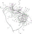
Fig. 1 is a schematic perspective view of a whole hemming sewing machine for round fabric based on a double needle type horizontal cylinder type double-stitch sewing machine according to an embodiment of the present invention.
Fig. 2 is an enlarged perspective view of a fabric guide portion and a fabric edge folding guide device, which are main portions of the hemming sewing machine.
Fig. 3 is a perspective view of the main part of the hemming sewing machine in a further enlarged state.
Fig. 4 is an enlarged perspective view of a main part showing a detailed structure of a fabric guide portion of the hemming sewing machine.
Fig. 5 is a perspective view showing a main part of a state in which a round fabric is placed on the hemming sewing machine.
Fig. 6 is an enlarged perspective view of a main part of the state of the turning-back guiding operation of one end edge portion of the round fabric in the hemming sewing machine, as seen from the front.
Fig. 7 is an enlarged perspective view of a main part of the hemming sewing machine in a state where the edge of the hemming portion of the round fabric moves to the fabric guide portion, as viewed from the front.
Description of the reference numerals
4. Machine needle
5. Fabric presser foot
6. Needle plate
7. Fabric end edge turning-back guiding device
8. Fabric guide part
8A fabric end edge guide surface
8B lower part material guiding component
10A first fabric end edge position detector
10B second fabric end edge position detector
10C third fabric end edge position detector
13A first air ejection tube
13B second air ejection tube
13C third air jet pipe
14. Holding piece at other end of fabric
M double-thread lockstitch sewing machine (Sewing machine main body)
H surface fabric end edge position adjustment mechanism
W-shaped round fabric
One end side edge of the We round fabric
WS hemming sewing portion
WSe hemming sewing portion end edge
Y sewing travelling direction
Detailed Description
Hereinafter, embodiments of the present invention will be described with reference to the drawings.
Fig. 1 is a schematic perspective view of a whole hemming machine for round fabric using a double-needle type horizontal double-thread lockstitch sewing machine as a sewing machine body according to an embodiment of the present invention, fig. 2 is an enlarged perspective view of a main part of the hemming machine, fig. 3 is an enlarged perspective view of a main part of the hemming machine, fig. 4 is an enlarged perspective view of a main part showing a detailed structure of a fabric guide portion of the hemming machine, and fig. 5 to 7 are enlarged perspective views showing a placement state of the round fabric on the hemming machine, a turning-back guiding operation state of an end edge portion of the round fabric, and an end edge moving state of the hemming portion.
In the following description, "up and down", "left and right", and "front and rear" indicated by arrows are used in fig. 2. Here, "front" is a side closer to the sewing operator, "rear" is a side farther from the sewing operator, and "left and right" are left and right when viewed from the front.
As shown in fig. 1, in the double-needle type horizontal tubular double-stitch sewing machine M, the sewing machine arm 2 and the sewing machine base 3 extend from the upper and lower parts of the sewing machine stile 1 to the left side in a substantially parallel manner. The sewing machine arm 2 is internally mounted with: a main shaft of the sewing machine, a needle driving mechanism for reciprocating the left and right needles 4, 4 (see fig. 2) arranged in parallel in a direction substantially orthogonal to the sewing traveling direction Y in the up-down direction, a fabric presser foot 5, a presser foot lifting driving mechanism for driving the presser foot 5 to lift in the up-down direction, a power transmission mechanism for each driving mechanism, and the like are well known, and therefore, schematic drawings and detailed description thereof are omitted.
A needle plate 6 for guiding the conveyance of the round fabric in the sewing traveling direction Y is fixed to the upper surface of the sewing machine bed 3, and a needle drop portion as a needle drop position is formed in the needle plate 6. The sewing machine base part 3 at the lower part of the needle plate 6 is provided with: a feed tooth for conveying fabric downwards, which intermittently and forcedly conveys one end edge part of the round fabric W placed on the needle plate 6 to the sewing advancing direction Y; a looper capable of advancing and retreating along a left-right direction substantially orthogonal to an up-down reciprocating path of the needles 4, 4 so as to hold a looper thread, and grasping two needle thread loops formed under a needle plate 6 by the needles 4, 4 during the advancing; and a thread cutting device, etc. Here, since the structure and operation of the feeding teeth, loopers, thread cutting devices, and advancing and retreating mechanisms of loopers for lower conveying of fabric are well known, schematic drawings and detailed description are omitted.
In the horizontal tubular double-seam lockstitch sewing machine M, a fabric edge folding guide device 7 is provided at a position (forward position) upstream of the needle falling position of the needle plate 6 in the sewing travel direction Y. As shown in fig. 2, the fabric edge folding guide device 7 includes a guide plate 71 disposed in front of the needle drop section and a fixed gauge 72 bent into a substantially "h" shape in front view, folds down one end side edge portion We of the round fabric W (see fig. 5 to 7) fed toward the needle drop position by a predetermined width, and after the lower side of the remaining fabric is overlapped with the guide plate, the end edge of the folded portion overlapped up and down is brought into sliding contact with the curved inner surface (fabric edge guide surface) of the fixed gauge 72 to guide the feeding movement toward the sewn portion including the needles 4, the fabric presser foot 5, the needle plate 6, and the like.
The fabric edge folding guide 7 is provided with a plurality of air pipes 73 for introducing high-pressure air from an air supply source, not shown, in parallel in the front-rear direction. The high-pressure air supplied to the air pipe 73 located at the front position is ejected in the left direction in front of the guide plate 71 and the gauge 72, and the ejected high-pressure air is ejected onto the one end side edge We portion of the fabric W, thereby performing a function of turning the one end side edge We portion of the round fabric W downward and assisting the introduction thereof between the guide plate 71 and the gauge 72.
The high-pressure air supplied to the remaining air pipe 73 is ejected along the lower surface of the guide plate 71 inside the fixed gauge 72, and functions as follows: the edge of the fabric W overlapped with the lower surface of the guide plate 71 is biased to move leftward, so that the width corresponding to the length of the guide plate 71 overlaps the remaining fabric, and the round fabric W overlapped with a certain width is fed to the needle drop position to be sewn.
In the horizontal tubular double-seam sewing machine M, a fabric guide 8 is provided at a position (forward position) upstream of the fabric edge folding guide 7 in the sewing traveling direction Y, and the fabric guide 8 has a fabric edge guide surface 8A that is in sliding contact with one end side edge We of the round fabric W and guides the conveying movement of the one end side edge We of the round fabric W toward the fabric edge folding guide 7. The fabric guide portion 8 is provided with: the first to third fabric end edge position detectors 10A, 10B, 10C, the air discharge tubes 13A, 13B, 13C as the first to third air discharge devices, and the lower fabric guide member 8B that is in sliding contact with the end edge WSe of the hemmed portion WS and guides the hemmed portion end edge WSe to move toward the second fabric end edge position detector 10B.
As shown in fig. 2, the fabric guide 8 has 4 support plates 82, 88, 89, 90 fixedly connected to each other along the sewing traveling direction Y, wherein the fabric support 85 is attached to the support plate 82 and the fabric supports 83, 84 are attached to the support plate 88. A support rod 81 extending from the support plate 88 in a right lateral direction orthogonal to the sewing traveling direction Y is slidably supported by the fixed slider 86, a connecting plate 87 is fixed to an end portion thereof, and a double-acting pneumatic cylinder, not shown, is connected to the connecting plate 87. Thus, the fabric guide 8 is configured to be movable in the left-right direction L-R by driving the fabric guide by a double-acting pneumatic cylinder. The support plate 82 is a flat plate mounted in a vertical posture with respect to the support bar 81. The left side surface of the support plate 88 to which the fabric holders 83, 84 are attached is formed into the fabric edge guide surface 8A. The fabric holders 83, 84, 85 are formed by a circular tube or a circular rod member bent in a substantially "o" shape, and as described above, the fabric holder 85 is attached to the support plate 82 such that the bent portion of the tip extends leftward, one end of the fabric holder 83 is attached to the support plate 88 such that the bent portion of the tip extends leftward from the support plate 82 through the support plate 88, the other end is attached to the support plate 88 such that the bent portion of the tip extends leftward, and the fabric holder 84 is attached to the support plate 88 such that the bent portion extends leftward. The lower fabric guide member 8B is attached to the support plate 90 of the fabric guide portion 8.
The fabric support 83 is disposed along a lower edge of the support plate 82 that is inclined downward in front of the fabric support. The fabric holder 84 is disposed to have a smaller width and a smaller size than the fabric holder 83, and is housed inside the fabric holder 83 at a position adjacent to the upper side thereof. The fabric holder 85 is wider and longer than the fabric holder 83 in width and is disposed farther upward in front of the fabric holder 83. The upper edge portion 85a of the fabric support 85 is formed in an inclined posture which is located more rearward as going to the right.
The first air discharge pipe 13A provided in the fabric guide 8 discharges air toward the vicinity of one end of the round fabric W adjusted to a predetermined position by a fabric edge position adjustment mechanism H (see fig. 1) described later, and thereby has a function of holding the one end side edge We of the round fabric W pressed against the fabric edge guide surface 8A. The second air discharge pipe 13B discharges air in conjunction with the position adjustment operation of the fabric edge position adjustment mechanism H for adjusting the position of the one end side edge We of the round fabric W, thereby assisting the position adjustment of the one end side edge We of the round fabric W pressed against the fabric edge guide surface 8A of the fabric guide 8. The third air discharge pipe 13C intermittently discharges air toward the one end side edge of the placed round fabric W, and thereby has a function of correcting bending wrinkles or curls generated in the one end side portion of the round fabric W due to the fabric weight or the like. The air discharge pipes 13A, 13B, and 13C are connected to an air supply source, not shown, via air pipes, not shown.
The first fabric edge position detector 10A provided in the fabric guide 8 is attached to the upper portion of the fabric guide 8, and detects the position of the one end side edge We of the round fabric W. The second fabric edge position detector 10B is disposed on the upstream side in the sewing traveling direction Y than the first fabric edge position detector 10A and on the left lateral outer side of the sewing machine body than the first fabric edge position detector 10A, and detects a downstream portion in the vicinity of the edge position of the hemming portion WS of the round fabric W sewn by the sewn portion. The third fabric edge position detector 10C is disposed upstream of the second fabric edge position detector 10B in the sewing traveling direction Y and further to the left lateral outside of the sewing machine body than the first fabric edge position detector 10A, and detects the position of the one end side edge We of the round fabric W.
The double-needle type double-stitch sewing machine M as a sewing machine body having the above-described structure is attached with a fabric edge position adjusting mechanism H that is separate from the sewing machine M. As shown in fig. 1, the fabric edge position adjusting mechanism H is disposed at a position spaced apart from the sewing machine M in a direction substantially orthogonal to the sewing traveling direction Y toward the left lateral outside on the upstream side of the needle falling portion of the needle plate 6 of the sewing machine M, and has a fabric other end gripper 14 having a pair of gripping pieces capable of gripping the other end side opposite to the one end of the round fabric W sewn by the sewing machine M, and the pair of gripping portions of the fabric other end gripper 14 are configured to be openable and closable. The other end gripper 14 is configured to be reciprocally movable in the vertical direction (a specific direction) by a driving unit 15 including a stepping motor, a rack, a pinion, and the like, so that the position of one end side edge of the round fabric W is adjusted in the right-left direction orthogonal to the sewing traveling direction Y, and is controlled to move obliquely downward by a control unit driving based on the detection result of the first fabric edge position detector 10A, and is controlled to move obliquely upward by a control unit driving based on the detection result of the third fabric edge position detector 10C. The fabric edge position adjusting mechanism H is fixedly provided on the same sewing machine table as the double-needle double-thread lockstitch sewing machine M as a sewing machine body via the table 16.
Next, with reference to fig. 5 to 7, a sewing operation of hemming one end edge portion of the circular fabric W such as the hem portion of the T-shirt by a hemming sewing machine for the circular fabric having the double needle type cross cylindrical double stitch sewing machine M and the fabric end edge position adjusting mechanism H according to the present embodiment configured as described above will be described.
Before sewing starts, the other end portion Wb of the round fabric W is held by inserting the other end portion Wb of the round fabric W between a pair of holding pieces of the other end portion Wb of the round fabric W and closing the pair of holding pieces, and in this state, as shown in fig. 5, the other end portion Wb of the round fabric W is guided to the fabric folding guide 7 at one end side hem portion of the round fabric W, and one end side edge portion We of the round fabric W is folded back to overlap the back side of the fabric, and the folded back fabric portion (sewn portion) is placed on the needle plate 6. Then, the presser foot 5 is driven to descend, and the edge We on the upstream side in the sewing traveling direction Y is placed at a predetermined position of the fabric guide 8.
In this state, the horizontal tubular double-thread lockstitch sewing machine M starts the rotating operation, and the one end side edge portion of the round fabric W is fed out so as to be supported by the fabric holders 83, 84, 85 of the fabric guide 8, and then is introduced between the guide plate 71 and the fixed gauge 72 of the fabric folding guide 7, and the one end side edge portion is folded back to overlap the back side of the fabric. Then, the folded portion of the round fabric W overlapped up and down is forcibly transferred intermittently in the sewing traveling direction Y by the fabric lower conveying feed tooth acting on the lower surface of the folded portion and the presser foot 5 acting on the upper surface of the folded portion, and hemming sewing in which a double-thread lockstitch is formed on the entire periphery of the sewn portion (overlapped fabric portion) of the round fabric W is performed by a series of sewing operations such as a lifting operation by the rotation operation of the sewing machine M, a advancing and retreating operation of the looper, and the like by the left and right needles 4, 4.
In the hemming process, the one end side edge position of the round fabric W that is fed out and moved to the fabric edge folding guide 7 so as to be supported by the fabric holders 83, 84, 85 of the fabric guide 8 may be displaced in the left-right direction by an external force such as the dead weight of the middle portion of the round fabric between the sewing machine M and the fabric edge position adjusting mechanism H.
In this case, according to the hemming sewing machine of the present embodiment, the one end side edge position of the round fabric W is always monitored by the first fabric edge position detector 10A, and the fabric other end gripping piece 14 of the fabric edge position adjusting mechanism H is controlled to move obliquely downward in response to the detection that the one end side edge We of the round fabric W fed to the fabric edge folding guide 7 is displaced to the left side and is deviated from the detection range (light receiving range) of the first fabric edge position detector 10A.
Thus, the one end side edge We of the round fabric W can be automatically adjusted to a predetermined position over the entire length thereof, and the folded width of the one end side edge We can be kept substantially constant, so that appropriate and satisfactory hemming can be performed at all times.
When the downstream portion in the vicinity of the edge position WSe of the hemming portion is moved to the lower fabric guide member 8B of the fabric guide member 8 by hemming, the edge WSe of the hemming portion is moved in sliding contact with the fabric guide member 8B, the downstream portion in the vicinity of the edge position of the hemming portion is detected by the second fabric edge position detector 10B, and based on the detection result, the fabric guide member 8 is moved to a predetermined position in the left-right lateral direction L-R of the sewing machine main body by a double-acting pneumatic cylinder (not shown) while the hemming is continued, whereby the starting end portion of the hemming portion and the one end edge of the round fabric (the terminal end portion of the hemming portion) fed into the sewing portion in a folded state can be aligned so that they are substantially on a straight line, and the edge of the hemming portion can be prevented from being folded back again based on the detection result of the first fabric edge position detector 10A again, so that hemming with good appearance can be completed circumferentially over the lower hem portion.
Further, it is needless to say that the starting end portion of the hemming portion WS and the end portion of the hemming portion WS are continuously hemmed over a predetermined length even after the completion of the alignment, and then the driving of the sewing machine is stopped and the sewing machine is switched to a manual sewing state by the operator, whereby the hemming distance by the manual sewing can be shortened as much as possible, and the starting end portion of the hemming portion and the end portion of the hemming portion can be reliably, easily and promptly aligned even by the manual operation.
In particular, as in the present embodiment, the first to third air discharge pipes 13A, 13B, 13C are provided in the fabric guide portion 8, whereby the following functions can be exhibited: the holding function of pressing the one end side edge We of the round fabric W against the fabric edge guide surface 8A, the function of assisting the position adjustment operation of pressing the one end side edge We of the round fabric W against the fabric edge guide surface 8A of the fabric guide portion 8, and the function of correcting the bending wrinkles or curls generated by the weight of the fabric or the like in the one end side portion of the round fabric W can be performed more reliably and appropriately.
In the above-described embodiment, the other end gripper 14 of the fabric in the fabric edge position adjustment mechanism H is configured to be capable of being driven to reciprocate in the vertical direction, but the other end gripper 14 of the fabric may be configured to be capable of being driven to reciprocate in the vertical direction, or the other end gripper 14 of the fabric may be configured to be capable of being driven to reciprocate in the horizontal direction.
The sewing machine to which the fabric edge position adjustment mechanism H is attached is not limited to the multi-needle type horizontal cylindrical double-thread lockstitch sewing machine described above, and may be a lockstitch sewing machine in which lockstitch stitches are formed on the entire circumference of the overlapping portion of one end side of the circular fabric.
In the above embodiment, the other end of the fabric gripping member 14 of the fabric edge position adjustment mechanism H is configured to drive the pair of gripping pieces to be opened and closed freely, but the pair of gripping pieces may be configured to be driven to be opened and closed by swinging the pair of gripping pieces in a longitudinal direction or a pair of springs.
Claims (9)
1. A hemming sewing machine for round fabric comprising:
a sewing part comprising a needle plate for guiding the conveying of the round fabric to the sewing advancing direction, a needle formed in a manner of being capable of moving up and down by a needle falling part of the needle plate, and a fabric presser foot capable of lifting;
a fabric edge turning-back guide device which is arranged at an upstream side of the needle falling part of the sewing part in the sewing travelling direction, turns back one edge part of the round fabric downwards with a prescribed width, and sends out and guides the turning-back part which is overlapped up and down towards the sewing part; and
a fabric guide portion which is disposed at an upstream side of the fabric edge folding guide device in a sewing traveling direction and has a fabric edge guide surface which is in sliding contact with one end side edge of the round fabric to guide a feeding movement of the one end side edge of the round fabric to the fabric edge folding guide device,
the sewing part is used for sewing the folded-back part of the round fabric which is sent out and guided from the fabric end edge folded-back guiding device to the sewing part,
the hemming sewing machine of the round fabric is characterized by comprising:
a fabric edge position adjustment mechanism having a fabric other end gripping member capable of gripping the other end side of the round fabric, the fabric other end gripping member being configured to be driven to reciprocate in a specific direction so that one end edge portion of the round fabric is adjusted in a direction orthogonal to a sewing traveling direction, wherein the fabric other end gripping member is arranged at a position that is separated from the needle falling portion on an upstream side in the sewing traveling direction and in a direction orthogonal to the sewing traveling direction toward a lateral outside of the sewing machine body;
a first fabric edge position detector which is arranged above the fabric guide part and detects the edge position of one end part of the round fabric;
a second fabric edge position detector that is disposed on an upstream side of the first fabric edge position detector in a sewing traveling direction and on a lateral outer side of the sewing machine body in a direction orthogonal to the sewing traveling direction, and that detects a downstream portion in the vicinity of a hemming-sewn portion edge position of the round fabric sewn by the sewn portion; and
and a control unit that drives the fabric edge position adjustment mechanism to move in one direction of the specific direction so that the one end side edge position is adjusted to a predetermined position based on a detection result of the first fabric edge position detector for the one end side edge position of the round fabric, wherein the control unit continues hemming and moves the fabric guide portion to a predetermined position on the lateral outside of the sewing machine body in a direction orthogonal to the sewing traveling direction while continuing hemming and thereafter stops the sewing machine drive after hemming for a predetermined length.
2. The hemming sewing machine of a round fabric of claim 1 wherein:
the control unit drives the fabric edge position adjustment mechanism to move in the other direction in the specific direction so that the one end edge of the round fabric is adjusted to a non-detection position of the third fabric edge position detector when the third fabric edge position detector detects the one end edge of the round fabric, the third fabric edge position detector being disposed at a position on the upstream side in the sewing direction than the second fabric edge position detector and on the lateral outside of the sewing machine body in a direction orthogonal to the sewing direction than the first fabric edge position detector.
3. The hemming sewing machine of round fabric of claim 2 wherein:
the fabric guide part is provided with a fabric guide part which is positioned on the upstream side of the third fabric edge position detector in the sewing travelling direction and on the lateral outer side of the sewing machine main body in the direction orthogonal to the sewing travelling direction, and is in sliding contact with the edge of the hemming sewing part of the round fabric and guides the hemming sewing edge to move towards the second fabric edge position detector.
4. The hemming sewing machine of a round fabric of claim 1 wherein:
the fabric guide portion is provided with an air ejection device that ejects air toward the vicinity of one end edge portion of the round fabric adjusted to a predetermined position, thereby pressing the one end edge portion of the round fabric against the fabric end edge guide surface of the fabric guide portion.
5. The hemming sewing machine of a round fabric of claim 1 wherein:
the fabric guide portion is provided with an air ejection device that ejects air in conjunction with a position adjustment operation of the fabric edge position adjustment mechanism for the one end edge position of the round fabric, and presses the one end edge portion of the round fabric against the fabric edge guide surface side of the fabric guide portion.
6. The hemming sewing machine of claim 4 wherein the round fabric is characterized by:
the fabric guide portion is provided with an air ejection device that ejects air in conjunction with a position adjustment operation of the fabric edge position adjustment mechanism for the one end edge position of the round fabric, and presses the one end edge portion of the round fabric against the fabric edge guide surface side of the fabric guide portion.
7. The hemming sewing machine of round fabric of claims 1, 4, 5 or 6 wherein:
an air ejection device for curl correction is disposed in the fabric guide, and the air ejection device for curl correction intermittently ejects air toward an end edge of the round fabric reaching the fabric guide, thereby correcting a curl generated at the end of the round fabric.
8. The hemming sewing machine of round fabric of claim 1, 2 or 4 wherein:
the fabric edge position adjustment mechanism is configured to drive the fabric other end gripping member to move in the up-down direction or the up-down tilting direction based on a detection result of the one end side edge position of the round fabric by the first fabric edge position detector.
9. The hemming sewing machine of claim 7 wherein the round fabric is characterized by:
the fabric edge position adjustment mechanism is configured to drive the fabric other end gripping member to move in the up-down direction or the up-down tilting direction based on a detection result of the one end side edge position of the round fabric by the first fabric edge position detector.
Applications Claiming Priority (2)
| Application Number | Priority Date | Filing Date | Title |
|---|---|---|---|
| JP2019059384A JP2020142041A (en) | 2019-03-07 | 2019-03-07 | Round fabric hem sewing machine |
| JP2019-059384 | 2019-03-07 |
Publications (2)
| Publication Number | Publication Date |
|---|---|
| CN111663253A CN111663253A (en) | 2020-09-15 |
| CN111663253B true CN111663253B (en) | 2023-06-27 |
Family
ID=72355067
Family Applications (1)
| Application Number | Title | Priority Date | Filing Date |
|---|---|---|---|
| CN202010134787.6A Active CN111663253B (en) | 2019-03-07 | 2020-03-02 | Hemming sewing machine for round fabric |
Country Status (4)
| Country | Link |
|---|---|
| JP (1) | JP2020142041A (en) |
| CN (1) | CN111663253B (en) |
| TR (1) | TR202003472A2 (en) |
| TW (1) | TWI824120B (en) |
Families Citing this family (4)
| Publication number | Priority date | Publication date | Assignee | Title |
|---|---|---|---|---|
| CN112709016B (en) * | 2020-12-23 | 2025-05-16 | 浙江威比玛智能缝制科技有限公司 | An all-in-one machine for bag edge wrapping and crimping |
| CN115094578B (en) * | 2022-06-06 | 2023-11-07 | 珠海运控瑞奇数控科技有限公司 | Label aligning mechanism, rubber band machine and label aligning method |
| CN118065063A (en) * | 2024-02-18 | 2024-05-24 | 宁波申洲针织有限公司 | A part processed by a hem cuff roll-down three-fold interlock sewing machine |
| CN118639397B (en) * | 2024-08-13 | 2024-11-29 | 启东市南洋工业缝纫机有限公司 | Automatic fabric folding device for sewing machine and sewing machine |
Citations (2)
| Publication number | Priority date | Publication date | Assignee | Title |
|---|---|---|---|---|
| JP2017074269A (en) * | 2015-10-16 | 2017-04-20 | Juki株式会社 | sewing machine |
| JP2018130518A (en) * | 2017-02-16 | 2018-08-23 | ヤマトミシン製造株式会社 | Fabric holding device for sewing machine |
Family Cites Families (7)
| Publication number | Priority date | Publication date | Assignee | Title |
|---|---|---|---|---|
| JP5967540B2 (en) * | 2012-09-18 | 2016-08-10 | ヤマトミシン製造株式会社 | Hem stitch machine |
| JP5984093B2 (en) * | 2013-09-24 | 2016-09-06 | ヤマトミシン製造株式会社 | Fabric edge curl straightener |
| JP6467699B2 (en) * | 2014-09-25 | 2019-02-13 | ヤマトミシン製造株式会社 | sewing machine |
| JP6410145B2 (en) * | 2014-12-19 | 2018-10-24 | ヤマトミシン製造株式会社 | Hem stitch sewing machine |
| JP6861934B2 (en) * | 2016-04-05 | 2021-04-21 | ヤマトミシン製造株式会社 | Sewing machine with automatic stop device for detecting the end of sewing |
| JP2018114096A (en) * | 2017-01-18 | 2018-07-26 | ヤマトミシン製造株式会社 | sewing machine |
| JP2019000608A (en) * | 2017-06-16 | 2019-01-10 | ヤマトミシン製造株式会社 | Cloth feeding auxiliary guide device for sewing machine |
-
2019
- 2019-03-07 JP JP2019059384A patent/JP2020142041A/en active Pending
-
2020
- 2020-03-02 CN CN202010134787.6A patent/CN111663253B/en active Active
- 2020-03-06 TR TR2020/03472A patent/TR202003472A2/tr unknown
- 2020-03-06 TW TW109107373A patent/TWI824120B/en active
Patent Citations (2)
| Publication number | Priority date | Publication date | Assignee | Title |
|---|---|---|---|---|
| JP2017074269A (en) * | 2015-10-16 | 2017-04-20 | Juki株式会社 | sewing machine |
| JP2018130518A (en) * | 2017-02-16 | 2018-08-23 | ヤマトミシン製造株式会社 | Fabric holding device for sewing machine |
Also Published As
| Publication number | Publication date |
|---|---|
| TWI824120B (en) | 2023-12-01 |
| TW202045791A (en) | 2020-12-16 |
| JP2020142041A (en) | 2020-09-10 |
| TR202003472A2 (en) | 2021-06-21 |
| CN111663253A (en) | 2020-09-15 |
Similar Documents
| Publication | Publication Date | Title |
|---|---|---|
| CN111663253B (en) | Hemming sewing machine for round fabric | |
| US5709162A (en) | Semi-automatic method to attach circular collars to T-shirts | |
| CA2184440C (en) | Sewing sleeves on shirt bodies | |
| JP5616587B2 (en) | Sewing machine with belt loop | |
| CN105714481B (en) | Hemming sewing machine | |
| JPH0732827B2 (en) | Deflection correction device for cloth edge in octopus seam sewing machine | |
| JP4149630B2 (en) | Sewing sewing machine | |
| JP2015062481A (en) | Fabric edge curl straightener | |
| JP2017221644A (en) | Covering chain stitch sewing machine | |
| US5522332A (en) | Waist band attachment system | |
| US5562060A (en) | Waist band attachment system | |
| CN110714280A (en) | Fabric adjusting device of sewing machine | |
| CN107938184B (en) | Control method of multi-handpiece pocket patching machine | |
| JP2018130518A (en) | Fabric holding device for sewing machine | |
| JPH0311797B2 (en) | ||
| CN109629130A (en) | A kind of feeding mechanism of patch bottom shelves sewing machine | |
| JPH0424070A (en) | Ring-shaped rubber-inserting device in sewing machine | |
| US5622129A (en) | Pneumatic tensioning arm for automated sewing machine | |
| CN209686052U (en) | A kind of patch bottom shelves sewing machine | |
| CN107687050B (en) | Method for making trousers | |
| JP5808969B2 (en) | Sewing machine with belt loop | |
| CN101724991B (en) | Belt-loop sewing machine | |
| CN209686041U (en) | A kind of feeding mechanism of patch bottom shelves sewing machine | |
| CN209686053U (en) | A kind of material folding mechanism of patch bottom shelves sewing machine | |
| JPH03168178A (en) | Thread chain-sewing device for attaching tape |
Legal Events
| Date | Code | Title | Description |
|---|---|---|---|
| PB01 | Publication | ||
| PB01 | Publication | ||
| SE01 | Entry into force of request for substantive examination | ||
| SE01 | Entry into force of request for substantive examination | ||
| GR01 | Patent grant | ||
| GR01 | Patent grant |